EP1704884A1 - Dispositif pour la distribution dosée d'un produit fluide - Google Patents
Dispositif pour la distribution dosée d'un produit fluide Download PDFInfo
- Publication number
- EP1704884A1 EP1704884A1 EP05006543A EP05006543A EP1704884A1 EP 1704884 A1 EP1704884 A1 EP 1704884A1 EP 05006543 A EP05006543 A EP 05006543A EP 05006543 A EP05006543 A EP 05006543A EP 1704884 A1 EP1704884 A1 EP 1704884A1
- Authority
- EP
- European Patent Office
- Prior art keywords
- engagement
- drive member
- support surface
- axially
- drive
- Prior art date
- Legal status (The legal status is an assumption and is not a legal conclusion. Google has not performed a legal analysis and makes no representation as to the accuracy of the status listed.)
- Granted
Links
- 0 C[C@@]1C=C(C2)C2(C*)CC1 Chemical compound C[C@@]1C=C(C2)C2(C*)CC1 0.000 description 1
Images




Classifications
-
- A—HUMAN NECESSITIES
- A61—MEDICAL OR VETERINARY SCIENCE; HYGIENE
- A61M—DEVICES FOR INTRODUCING MEDIA INTO, OR ONTO, THE BODY; DEVICES FOR TRANSDUCING BODY MEDIA OR FOR TAKING MEDIA FROM THE BODY; DEVICES FOR PRODUCING OR ENDING SLEEP OR STUPOR
- A61M5/00—Devices for bringing media into the body in a subcutaneous, intra-vascular or intramuscular way; Accessories therefor, e.g. filling or cleaning devices, arm-rests
- A61M5/14—Infusion devices, e.g. infusing by gravity; Blood infusion; Accessories therefor
- A61M5/142—Pressure infusion, e.g. using pumps
- A61M5/14244—Pressure infusion, e.g. using pumps adapted to be carried by the patient, e.g. portable on the body
-
- A—HUMAN NECESSITIES
- A61—MEDICAL OR VETERINARY SCIENCE; HYGIENE
- A61M—DEVICES FOR INTRODUCING MEDIA INTO, OR ONTO, THE BODY; DEVICES FOR TRANSDUCING BODY MEDIA OR FOR TAKING MEDIA FROM THE BODY; DEVICES FOR PRODUCING OR ENDING SLEEP OR STUPOR
- A61M5/00—Devices for bringing media into the body in a subcutaneous, intra-vascular or intramuscular way; Accessories therefor, e.g. filling or cleaning devices, arm-rests
- A61M5/14—Infusion devices, e.g. infusing by gravity; Blood infusion; Accessories therefor
- A61M5/142—Pressure infusion, e.g. using pumps
- A61M5/145—Pressure infusion, e.g. using pumps using pressurised reservoirs, e.g. pressurised by means of pistons
- A61M5/1452—Pressure infusion, e.g. using pumps using pressurised reservoirs, e.g. pressurised by means of pistons pressurised by means of pistons
- A61M5/14566—Pressure infusion, e.g. using pumps using pressurised reservoirs, e.g. pressurised by means of pistons pressurised by means of pistons with a replaceable reservoir for receiving a piston rod of the pump
-
- A—HUMAN NECESSITIES
- A61—MEDICAL OR VETERINARY SCIENCE; HYGIENE
- A61M—DEVICES FOR INTRODUCING MEDIA INTO, OR ONTO, THE BODY; DEVICES FOR TRANSDUCING BODY MEDIA OR FOR TAKING MEDIA FROM THE BODY; DEVICES FOR PRODUCING OR ENDING SLEEP OR STUPOR
- A61M5/00—Devices for bringing media into the body in a subcutaneous, intra-vascular or intramuscular way; Accessories therefor, e.g. filling or cleaning devices, arm-rests
- A61M5/14—Infusion devices, e.g. infusing by gravity; Blood infusion; Accessories therefor
- A61M5/142—Pressure infusion, e.g. using pumps
- A61M5/14244—Pressure infusion, e.g. using pumps adapted to be carried by the patient, e.g. portable on the body
- A61M2005/14264—Pressure infusion, e.g. using pumps adapted to be carried by the patient, e.g. portable on the body with means for compensating influence from the environment
-
- A—HUMAN NECESSITIES
- A61—MEDICAL OR VETERINARY SCIENCE; HYGIENE
- A61M—DEVICES FOR INTRODUCING MEDIA INTO, OR ONTO, THE BODY; DEVICES FOR TRANSDUCING BODY MEDIA OR FOR TAKING MEDIA FROM THE BODY; DEVICES FOR PRODUCING OR ENDING SLEEP OR STUPOR
- A61M5/00—Devices for bringing media into the body in a subcutaneous, intra-vascular or intramuscular way; Accessories therefor, e.g. filling or cleaning devices, arm-rests
- A61M5/14—Infusion devices, e.g. infusing by gravity; Blood infusion; Accessories therefor
- A61M5/168—Means for controlling media flow to the body or for metering media to the body, e.g. drip meters, counters ; Monitoring media flow to the body
- A61M5/16831—Monitoring, detecting, signalling or eliminating infusion flow anomalies
Definitions
- the invention relates to devices for the metered administration of fluid products in biotechnological applications, preferably in medical, including veterinary and pharmaceutical applications.
- it relates to infusion devices and injection devices.
- infusion devices and injection devices that dispense a product to be administered by means of a motor-driven reciprocating pump in the case of infusion devices or by means of a manually operated reciprocating pump in the case of injection devices from a product reservoir.
- infusion devices of the reciprocating piston is usually driven by a rotary drive, wherein the rotational movement of the drive is transmitted by means of a spindle drive in the linear movement of the piston.
- a spindle drive often serves to select the dose of product to be administered, while the linear movement of the piston is effected directly manually.
- rack gears are also common.
- the aforementioned examples of administration devices have in common that the dosing accuracy depends significantly on how exactly the path length can be specified, which must cover the piston for the promotion of a certain product dose.
- infeed devices with which the product is often delivered over longer periods in small, discrete boli. It may happen that constructive features that basically serve to improve the dosing accuracy, at the same time can exert a disturbing influence, such as the ability of occlusion detection.
- An infusion device with an advantageously designed, automatic occlusion detection is in the DE 198 40 992 described, which is hereby incorporated by reference for the purposes of the invention.
- Another device with occlusion detection describes the WO 01/72357 A2 , For occlusion detection, the conveyor as a whole is supported by a sensor on the housing of the infusion device.
- a device for the metered administration of a fluid product comprises a housing, a reservoir for the product and a conveyor.
- the housing can directly form the reservoir itself.
- a container for example an ampoule, forms the reservoir.
- the container is from the Housing held in a defined position.
- such a container is inserted into the housing.
- the container can, as is usual with ampoules today, be ready-made by being filled with a defined amount of product and already a container sealing the rear sealing piston is received in the container. Ready-made ampoules of this type are common for self-administration of insulin in diabetes therapy.
- the product can be the already mentioned insulin, a growth hormone and in principle any other medically or, for example, cosmetically active product.
- the device according to the invention is preferably designed for self-administration.
- the conveyor comprises at least one drive member and at least one output member.
- the drive member is preferably motor driven, if the device is an infusion device, and preferably manually, if the device is an injection device, so that it performs a drive movement.
- the drive member and the output member are mechanically coupled to each other so that the drive movement of the drive member causes a driven movement of the output member.
- the output motion is or includes an axial movement axially supported by the drive member.
- the axial movement may be a different movement or may be superimposed on several other movements.
- the output movement is a pure, linear axial movement.
- the coupling between the drive member and the output member is a flank engagement, for the formation of which the drive member and the output member each have at least one engagement flank.
- both the at least one engagement flank of the drive member directly on the drive member and the at least one engagement flank of the output member are formed directly on the output member.
- the drive movement may be an axial movement, as may in particular be the case when the device is an injection device.
- the drive movement is more preferably a rotational movement and, in this case, particularly preferably about an axis along which the output member carries out the output movement.
- the output member can act directly on the product located in the reservoir during the output movement, for example by itself forming a reciprocating piston or permanently connected to a reciprocating piston. It can only be loose against one Press the piston. Also possible is an embodiment in which the output member acts only via a transmission member or a plurality of transmission elements on a directly acting on the product conveying element, such as a reciprocating piston, when it performs the driven movement.
- the conveyor may in particular be telescopic, as shown in the DE 197 17 107 A described in this regard. In each case, two adjacent, adjacently located telescopic stages form in such an embodiment a drive member and an output member according to the invention.
- Edge interventions as they are known in particular from threaded engagement and tooth engagement, have due to manufacturing transverse to the engaging flanks an axial clearance that can be detrimental to the dosing accuracy.
- An axial play can become noticeable in particular when the so-called siphoning effect occurs, i. if it comes in the container due to the Ausströmberger to a suction situation.
- a backlash reducing device which is both in a Einstelleingriff with both the drive member and the output member, in which the Spielreduzier recruited relative to the output member and the drive member is adjusted to such a setting position and secured in the set position so that the axial play inherent in the flank engagement is reduced or preferably eliminated altogether in comparison with the known flank-engaging couplings.
- the setting engagement with one of the two members of drive member and output member corresponds to the flank engagement between the drive member and the output member.
- the other adjustment engagement specifies the adjustment movement of the game reduction device along its adjustment path.
- the Verstellwegm available in this adjustment engagement is preferably so long that the game reduction device is not in its set position to stop with the relevant link, but still within the Verstellwegm available in this procedure.
- the two adjustment interventions can in particular also be of the same type or completely the same. In the latter case, they specify the course of the adjustment path together.
- the adjustment engagement with the drive member is preferably positive and non-positive, particularly preferably the adjustment engagement is a threaded engagement.
- the setting engagement with the output member preferably the same applies.
- the formation of both adjustment engagements of the game reduction device as a threaded engagement is particularly appropriate when the flank engagement between the drive member and the output member is also a threaded engagement, as the invention prefers.
- the adjusting movement predetermining adjusting engagement is in preferred embodiments, continuous in the sense that the axial play between the drive member and the driven member from its production-related output to preferably zero value can be reduced continuously in the setting engagement, as for example allows the preferred threaded engagement.
- the threaded engagement also has the advantage that the clearance reduction device is axially supported by the adjustment engagement itself in each position occupied via the adjustment path.
- the play reduction means is secured to one of the drive member and output member members against axial movement relative to the member concerned.
- the fuse may in particular be designed so that the game reduction means participates in the drive movement when the fuse between the drive member and the Spielreduzier adopted, and the output movement participates, if the fuse between the Spielreduzier recognized and the output member.
- the securing of the clearance reduction means in the adjustment engagement in the adjustment position can be effected solely by self-locking.
- the game reduction device is secured in its adjusted position in the secured adjustment engagement with a material fit. This also applies if this is a thread engagement.
- the cohesive securing is preferably carried out in the setting engagement with the drive member.
- a fuse on the Output member would basically also in kinematic reversal also possible.
- the backup can also be realized only in cooperation of the game reduction device with the drive member and the output member, in this case preferably in that the Spielreduzier worn elastic on both the drive member and the output member is supported.
- one of the drive member and output member is a rack and the other is an engaging in the rack driver.
- rack and pinions are known, for example, from Injekomspens, so that details need not be discussed.
- a game reducing device can be formed by means of a further driver, so that two drivers engage in the same row of teeth. By adjusting the axial distance of the two drivers can be reduced even with such a rack and pinion, the tolerance existing from home existing axial clearance.
- the game reduction device is preferably formed as a single adjustment member in one piece, which is at least axially stiff in both adjustment and according to the axial play to be reduced.
- a play reduction device should be axially rigid at least when it is secured in the adjusted position.
- a two-piece game reduction device could include a first adjustment member that is in an adjustment engagement with the drive member and a second adjustment member that is in a disengaging engagement with the output member. The two adjusting members would be displaced axially relative to one another up to the setting position and would have to be axially fixed to each other in the setting position or to fix themselves to one another in order to obtain the axial rigidity.
- the drive member is a rotary member, which is rotatably mounted for rotation about a rotation axis.
- the output member is a translationally movable in a translational translation member.
- a rotational drive movement of the drive member in a drive direction causes a translational output movement of the output member in the translation direction.
- the administering device is an infusion device, then the rotatably movable drive member is preferably supported so that it can not move relative to the reservoir, preferably relative to the housing, in and against the translation direction of the driven member.
- the rotary bearing comprises a bearing body which rotatably supports the drive member about its axis of rotation.
- the bearing body may be multi-part, wherein the plurality of parts in and against the translation direction are rigidly connected to each other, but preferably it is one-piece. It can also be formed directly from the housing of the device. But it can also be formed separately and inserted into the housing. Furthermore, it corresponds to preferredechsfbrmen when the bearing body in the training as a separate bearing body is a bearing sleeve which surrounds the drive member at least in an axial section.
- the support surfaces can be formed either directly from the bearing body or the drive member, or it is the relevant support surface formed by a separate body, which is then axially stiff, preferably completely stiff, connected to either the bearing body or the drive member.
- At least one of the support surfaces is formed by the further game reducing means which is adjusted with the drive member or preferably the bearing body in a setting engagement in such a setting position and axially secured in the adjusted position on the bearing body or the drive member, that reduces the axial play of the pivot bearing and preferably eliminated.
- the drive member and the output member are stages of a telescopic conveyor, such as DE 197 17 107 A
- the pivot bearing forms the pivot bearing of the input stage of the conveyor.
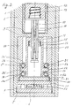
- Figure 1 shows in a longitudinal section as an example of an administering device an infusion device.
- the device comprises a housing having a first housing structure 1, and a second housing structure 2, a container 12 filled with an injectable product, and a delivery device which delivers the product metered out of the container 12 and through a subsequent catheter 8 for delivery administer.
- the administration can be carried out in particular subcutaneously, as is customary, for example, in diabetes therapy.
- the first housing structure 1 surrounds the second housing structure 2 and is referred to below as the enveloping structure 1.
- the second housing structure 2 supports components of the infusion device and is referred to below as the support structure 2.
- the container 12 has at an anterior end an outlet 14, via which the container interior is connected to the catheter 8.
- a piston 13 is received along a translation axis T in a conveying direction V to the container outlet 14 to be movable.
- the container 12 is open at its rear end. However, the piston 13 seals the container 12 towards the rear end.
- the enveloping structure 1 forms a solid shell in which the support structure 2, which is formed integrally by a support body 2, is inserted and fixed and forms a chassis of the housing.
- the enveloping structure 1 and the supporting body 2 form the housing of the device at least substantially.
- the support body 2 forms a first receiving space in which the container 12 is inserted, and a second receiving space for the conveyor.
- the container 12 is with its rear free edge to stop against a, a support shoulder forming, radially inwardly projecting support web 3 of the support body 2.
- the first receiving space formed by the support body 2 has at the front end an opening through which the container 12 is used. After insertion of the container 12, the opening is closed with a lid 7.
- the cover 7 is screwed to the support body 2, which is provided for this purpose with a thread 9.
- the support body 2 and the lid 7 could also be provided with a respective different engagement means for the releasable engagement, for example with cooperating locking devices.
- the lid 7 further forms the connecting element between the catheter 8 and the outlet 14 of the container 12.
- the lid 7 is facing the support shoulder of the support bar 3 a counter support shoulder on a Jacobstützsteg 7a, which presses against a front edge of the container 12 and thereby the container 12 against abutment against the support web 3, so that the container 12 is axially fixed relative to the support body 2.
- the cover 7 thus forms a front end element 7a, and the support web 3 forms a rear end element 3 of the first receiving space.
- the first receiving space is further shaped so that the container 12 has the correct position and orientation with respect to the translation axis T.
- the support body 2 supports the container 12 axially in and against the conveying direction V in a form-fitting manner, ie, by contact with the webs 3 and 7a serving as stops.
- the conveyor is supported in the same way axially between other stops of the support body 2.
- the conveyor comprises the piston 13, an output member 10, a drive member 20 and a motorized rotary drive.
- the output member 10 forms a translation member of the conveyor
- the drive member 20 forms a rotary member of the conveyor.
- the output member 10 is a piston threaded rod, d. H. a piston rod that is threaded.
- the output member 10 is provided with an external thread 11, which can be seen in the longitudinal section of Figure 2.
- the driven member 10 projects through the supporting web 3, so that it projects into the first receiving space and the second receiving space of the supporting body 2.
- the output member 10 is bolted to the piston 13.
- the screw connection is made with the insertion of the container.
- the support web 3 guides the driven member 10 linearly along the translation axis T.
- the support web 3 secures the driven member 10 against rotation relative to the support body 2.
- the thread 11 is broken in the embodiment for this purpose of at least one axial groove or flattening, in which the support web 3 intervenes.
- the drive member 20 is disposed entirely in the second receiving space of the support body 2. It is rotationally symmetrical to the translation axis T. It is sleeve-shaped and can therefore also be referred to as a drive sleeve.
- the drive member 20 forms at a front end of the sleeve radially inwardly projecting web, the output member 10th projects through.
- the drive member 20 forms at the inwardly projecting web an internal thread 21 which is in threaded engagement with the external thread 11 of the output member 10.
- the drive member 20 is rotatable about the translation axis T and mounted relative to the support body 2 is not axially movable. It has in a rear region a radially outwardly projecting, circumferential ridge 22, which is provided with an external toothing. About the external teeth, the drive member 20 is rotationally driven about the translation axis T. Its rotary drive receives it from a rotary motor 18, which is accommodated in a further receiving space. The further receiving space is formed by the enveloping structure 1 and is separated from the two receiving spaces of the supporting body 2.
- the motor 18 drives the output member 20 via a gear transmission with spur gears 19, of which an output gear 19 meshes with the external teeth of the output member 20.
- the threaded engagement as such between the output member 10 and the drive member 20 is subject to axial play.
- the metering accuracy of the discharge is therefore subject to an inaccuracy, at least to the extent of this inherent axial play.
- the axial position of the piston 13 is therefore indefinite in the extent of the axial play of the threads 11 and 21.
- a Spielreduzier disturbance is provided which is formed by means of an adjusting member 25 and which almost eliminates the axial play between the output member 10 and the drive member 20.
- the game reducing device is formed by a one-piece adjusting member 25.
- the adjusting member 25 is in an adjusting engagement with the driven member 10 and in a further setting engagement with the drive member 20.
- the adjusting member 25 and the two adjustment engagement are designed so that the axial clearance between the threads 11 and 21 is significantly reduced or preferably completely eliminated.
- the adjusting member 25 is formed as a threaded nut with an internal thread and an external thread. With its internal thread, the adjusting member 25 is in threaded engagement with the external thread 11 of the driven member 10. With its external thread, it is in threaded engagement with an internal thread 26 of the drive member 20.
- the internal thread 26 faces the external thread 11 and axially formed immediately behind the thread 21 , The internal thread and the external thread of the adjusting member 25 are at the same axial height, so that the adjusting member 25 may be axially thin and the game reducing means accordingly axially, d. H. along the translation axis T, short builds.
- the internal thread 26 only has to be so long that a secure adjustment engagement with the adjusting member 25 is ensured and the adjusting member 25 can be adjusted so far in this setting engagement so far that the desired reduction of the axial clearance of the thread 11 and 21 can be brought about.
- the internal thread 26 has a pitch which allows the adjustment member 25 to be adjusted in threaded engagement between the threads 11 and 21 and between the thread 11 and the internal thread of the adjusting member 25 in threaded engagement with the internal thread 26.
- Figure 3 shows an enlarged view of the threaded engagement of the threads 11 and 21 and the adjustment engagement between the thread 11 of the output member 10 and the internal thread of the adjusting member 25.
- the internal thread of the adjusting member 25 has the same pitch as the external thread 11.
- the pitch of the external thread of the adjusting member 25 and the internal thread 26 is greater or smaller than the pitch of the threads 11 and 21, but so slight that the adjustment of the adjusting member 25 is possible in the adjustment.
- the adjusting member 25 is adjusted in its setting engagement with the driven member 10 so that its with respect to the conveying direction V rear thread flanks 25f in contact with the front thread flanks 11 f of the external thread 11, while the front flanks 21 f of the driving thread 21st in contact with the rear flanks 11 f of the thread 11 of the output member 10 are.
- the adjusting member 25 is adjusted in its adjustment engagement with the drive member 20 relative to the drive member 20 against the conveying direction V until this state of the edge contact is established. In this state, the adjusting member 25 is fixed to the drive member 20 and thereby secured.
- the fuse is made adhesive in the exemplary embodiment by an adhesive agent is introduced into the adjustment engagement of the adjusting member 25 with the drive member 20.
- the setting position should be selected so that no or at least no practically relevant pressing forces are exerted on the output member 10 by the game reduction.
- the setting position is therefore chosen so that in the threaded engagement of the threads 11 and 21 remains a very small residual clearance, however, significantly smaller than this engagement alone, d. H. without game reduction, inherent thread play is.
- the setting position of the adjusting member 25 is selected so that the thread 21 remains the drive thread of the driven member 20.
- the setting position could also be chosen so that when adjusting the adjusting member 25 is moved against the rear thread flanks of the thread 11 and in this case the adjusting member 25 takes over the propulsion of the output member 10.
- preference is given to the selected for the embodiment and apparent from Figure 3 setting position of the adjusting member 25th
- FIGS. 4 and 5 An alternative embodiment of a game reduction device can be seen from FIGS. 4 and 5. Compared to the components of the embodiment of Figures 1 to 3, only the drive member 20 and in the alternative embodiment with "15" marked adjusting member are modified while the other components, in particular the driven member 10, are unchanged. As a further difference, the alternative game reduction device additionally comprises an elastic return element 17 in the form of a mechanical compression spring.
- the adjusting member 15 is as already used the adjusting member 25 in the output member 20 forming sleeve. However, the adjusting member 15 is connected to the output member 20 axially linearly displaceable and secured against rotation.
- the adjustment engagement of the adjusting member 15 with the drive member 20 is therefore a linear guide.
- the linear guide is formed by an axial, straight guideway 29 on the shell inner surface of the driven member and an engaging member 16 (FIG. 5) of the adjusting member 15 engaging in the guideway 29.
- the guideway 29 is bounded in the conveying direction V by the radially inwardly projecting web of the drive member 20, which forms the drive thread 21. Rearward, the guide rail 29 is open, so that the adjusting member 15 can be inserted.
- the return element 17 is used.
- the restoring element 17 is supported in the conveying direction on the web of the drive member 20 forming the drive thread 21 and against the conveying direction on the adjusting member 15.
- FIG. 4 shows this state before assembly with the output member 10.
- the adjusting member 15 is first inserted with the return element 17 in the drive member 20 in the adjustment handle with the guide rail 29 and pressed against the return element 17 with a certain force.
- the output member 10 is then bolted first to the adjusting member 15 and then to the drive thread 21.
- the Einstelleingriff push the rear thread flanks of the internal thread of the adjusting member 15 with a resilient force against the pointing in the conveying direction V thread flanks of the thread 11 of the output member 10.
- the adjusting member 15 is thus secured by the elasticity force of the return member 17 in the setting position.
- the infusion device of the embodiment has as a special feature, but as basically from the DE 198 40 992 A is known, an occlusion detection, which is also an axial play inherent, under which the dosing accuracy may suffer.
- This inherent, second axial play has its cause in that the entire conveyor, in particular the output member 10 and the drive member 20 is axially supported by a sensor 33 on the support body 2.
- the sensor 33 serves to determine the force required to move the piston 13 along the translation axis T.
- the sensor may be based on a strain measurement, for example.
- a physical variable representing the fluid pressure in the container 12 is measured, in order to detect any possible occlusion or possible leak as early as possible during product administration.
- the occlusion and / or leak detection and the sensor 33 are concerned, in the following only the aspects relating to the axial play will be discussed and, moreover, the example referred to DE 198 40 992 A directed.
- the conveyor is axially supported by the sensor 33.
- the drive member 20 is rotatably mounted in a bearing body 30 and axially secured to the bearing body 30.
- the bearing body 30 is inserted into the second receiving space of the support body 2 and secured against rotation.
- the support body 2 guides the bearing body 30 axially by sliding contact.
- the bearing body 30, and thus together the output member 10 and the drive member 20, is axially supported by the sensor 33 on the support body 2, that the sensor 33, the entire acting between the bearing body 30 and the support body 2 and directed against the conveying direction V. Absorbs axial force. In the conveying direction V of the bearing body 30 against the support body 2 to stop.
- the Bearing body 30 also supports the motor 18 and the transmission 19 of the conveyor. In the exemplary embodiment, it is for this purpose formed with a lateral extension which projects through a lateral opening of the support body 2 in the lateral receiving space of the Gescousehüll Design 1, in which the motor 18, a controller and possibly a more extensive device management system are housed.
- the substantially hollow cylindrical support body 2 is provided for this purpose in its jacket with an opening through which also the sensor 33 projects with a sensor connection side, where it is connected to the controller and a display.
- the sensor 33 forms an elastic bending beam, which is firmly clamped at both ends.
- the holder of the sensor 33 serves as a integrally molded sensor carrier 37 which is slidably axially guided by the support body 2 and is fixedly connected via a contact point 6 and the sensor 33 against the rear opening edge of the bearing body 30 to stop or optionally with the bearing body 30. Since the sensor carrier 37 also participates in each axial movement of the bearing body 30 when there is only stop contact, it is attributed to the bearing body 30 and thus to the conveyor.
- a contact element 5 which serves as another adjustment member. 5 serves.
- the adjusting member 5 forms the contact point 6 for the sensor 33.
- the contact point 6 is a cam which protrudes on the translation axis T from the front of the adjusting member 5 in the conveying direction V.
- the bearing body 30 is supported via the sensor 33 axially only at the contact point 6 quasi selectively on the translation axis T.
- the setting member 5 is in a setting engagement with the support body 2. Also this setting engagement is a threaded engagement in the exemplary embodiment, namely between an internal thread 4 at the rear end of the support body 2 and a corresponding external thread of the adjusting member 5.
- the adjusting member 5 is a circular cylindrical disc, the axially is just so thick that it is provided for a sufficiently fixed Einstellingriff on its outer periphery with a sufficiently long thread.
- the setting position of the adjusting member 5 is selected so that the bearing body 30 against the support body 2 in the conveying direction to stop and at the same time the contact point 6, the back of the force sensor 33 just touched.
- the internal thread 4 of the support body 2 is sufficiently long to screw the adjusting body 5 and to be able to adjust in the adjustment position into this setting position.
- the setting position is preferably chosen so that a calibration curve of the calibrated sensor 33 is not changed, in particular that the zero point of the calibration curve is maintained.
- the offset of the sensor 33 is "zero"; when the fluid pressure in the container 12 corresponds to the ambient pressure. An offset is only obtained when priming the infusion device.
- the setting position can also be selected such that an offset is already set in the setting position before a priming.
- priming refers to the process by which the product-carrying parts are completely filled with the product up to and including an exit point of the catheter 8, which can be formed by a puncture cannula or a soft cannula.
- the adjusting member 5 is fixed in its setting position on the support body 2, preferably integrally connected to the support body 2.
- the material bond can be obtained for example by laser welding or preferably by an adhesive introduced into the setting engagement.
- an adjusting member 35 is provided.
- the adjusting member 35 is in an adjusting engagement with the bearing body 30. This setting engagement is a threaded engagement.
- the adjusting member 35 is a flat, disk-shaped screw with an external thread.
- the adjusting member 35 is at the rear end of the bearing body 30 screwed into the bearing body 30, which forms an internal thread 34, which is in the adjustment engagement with the external thread of the adjusting body 35.
- the adjusting member 35 is arranged so that beyond the forces originating from the rotary bearing, no other external forces can act on the adjusting member 35.
- the bearing body 30 form a facing against the conveying direction V first support surface 31 and the adjusting member 35 a support surface 31 facing the second support surface 32.
- the drive member 20 forms at its web 22 a pointing in the conveying direction V third Support surface 23, which faces the first support surface 31, and a facing against the conveying direction V fourth support surface 24, which faces the second support surface 32.
- a ball bearing 27 and between the support surfaces 32 and 24, another ball bearing 28 is held axially.
- Each of the ball bearings 27 and 28 forms a radial bearing and via the support surfaces 31 and 23 and 32 and 24, a thrust bearing.
- the ball bearings each have an inner and an outer bearing ring, which are rotatable relative to each other about the translation axis T and between which a plurality of balls is arranged, which transmit the radial and axial forces between the bearing rings.
- the inner bearing ring is denoted by 27i and the outer bearing ring by 27a.
- the ball bearing 28 has correspondingly an inner bearing ring 28i and an outer bearing ring 28a.
- the inner bearing rings 27i and 28i are radially on the outer peripheral surface of the driven member 20 and the outer bearing rings 27a and 28a are radially supported on the opposite inner circumferential surface of the bearing body 30.
- the adjusting member 35 is pressed in its setting position with a small axial force against the outer bearing ring 28a.
- the adjusting member 35 and the ball bearing 28 are only in contact with the outer bearing ring 28 a and the second support surface 32.
- the second support surface 32 is a closed circular, concentric with the axis of rotation T annular face of an annular web 36 which rises in the conveying direction V from the front of the adjusting member 35.
- the annular end face could also have interruptions.
- the support surface 32 could be formed by individually projecting cams.
- the outer bearing rings 27a and 28a have no axial contact with the support surfaces 23 and 24 of the drive member 20.
- the inner bearing rings 27i and 28i have no axial contact with the support surfaces 31 and 32.
- the axial force flow passes through the pivot bearing therefore exclusively on the contact of the Support surfaces 31 and 32 with the respective facing the outer bearing rings 27a and 28a and the contact between the support surfaces 23 and 24 and the respective facing the inner bearing rings 27i and 28i.
- the axial force is therefore transmitted within the ball bearings 27 and 28 exclusively by the balls. In this way, apart from manufacturing tolerances of the ball bearings 27 and 28 is an axially almost backlash-free rotary bearing.
- the adjusting member 35 is already secured in its set position as the previously described adjusting members.
- the securing to the bearing body 30 is also preferably cohesive and can be effected in particular by an adhesive, which is introduced into the adjustment engagement.
- an adhesive which is introduced into the adjustment engagement.
- other material connections such as laser welding, are also possible.
- the fuse is made in the adjustment procedure itself.
- the axial lengths of the adjustment of the adjusting members 5, 15, 25 and 35 in the adjustment handles are each so long that the respective adjustment member in the adjustment to the adjustment position against the body, with it in the adjustment is, can get into a stop contact, which blocks a further adjustment the same direction.
- the support body 2 has a thermal expansion in the axial direction, which is significantly closer to the axial thermal expansion of the container 12 than the housing of conventional devices.
- the support body 2 in particular consist of a material whose coefficient of thermal expansion differs at most by a factor of 5 from the thermal expansion coefficient of the material of the container 12. It is more preferable if the thermal expansion coefficients are as close to each other as possible or even equal.
- constructive measures are conceivable, for example, the production of the support body 2 as a composite body having a plurality of materials in the composite, for example, inserted in plastic stiffening body, which hinder the thermal expansion of Kunststoffinaterials in the axial direction.
- Preferred materials for obtaining a favorable thermal expansion have a thermal expansion coefficient of 30 ⁇ 10 -6 / K or less in the operating temperature range.
- the materials preferably have uniform thermal expansion in all directions.
- a composite support structure will, of course, have uneven thermal expansion with respect to the entire composite so that in such a case only axial thermal expansion and axial coefficient of thermal expansion are meant.
- Preferred construction materials for infusion devices and injection devices together with their thermal expansion coefficients ⁇ in the operating temperature range, are listed in the following table: material Thermal expansion coefficient ⁇ in 10 -6 / K Brass 18 to 19 stolen 10 to 12 aluminum 23 to 24 Polyamide PA 100 to 140 Polyoxymethylene POM 110 to 130 Polyethylene terephthalate PET 70 Polycarbonate PC 70 Polytetrafluoroethylene PTFE 60 to 200 Acrylonitrile Butadiene / styrene ABS 80 to 110 Glass 5 to 10 hard rubber 75 to 100
- a support body 2 or more generally a support structure 2 made of, for example, aluminum or an aluminum base alloy can already be compared to those plastic materials, which come in terms of thermal expansion of the container material, preferably glass, the closest, a significant improvement can be achieved because the thermal expansion coefficient of aluminum 3 is smaller than the thermal expansion coefficient of the plastic material closest to the container material in terms of the coefficient of thermal expansion.
- a brass material By using a brass material, a further improvement can be achieved. If the support structure is made of steel or has steel components in such an arrangement that the axial thermal expansion is significantly influenced by the steel components, an identical thermal expansion can even be achieved with the appropriate choice of the glass material in the best case.
- the support body 2 or more generally a support structure 2, which of course also assumes axial support function as the support body 2, formed as a composite body, a comparable favorable thermal expansion behavior can be achieved by Aussteifungs stresses, for example, in a plastic matrix embedded axial fibers, if the one or more stiffening body Thermal expansion as described above.
- the housing shell in the exemplary embodiment, the enveloping structure 1, has a thermal expansion according to the invention.
- the housing shell is formed as a composite body, for example as a plastic matrix with inserted stiffening bodies such as in particular axially oriented metal fibers.
- the supporting structure should, like the supporting body 2 by way of example, additionally also support the conveying device axially in both directions. It is also particularly favorable, if the conveyor as a whole has an axial thermal expansion which is located as close to the axial thermal expansion of the support structure, for example by the support structure and the components of the conveyor of the same material or possibly different materials as close as possible are made of mutually lying axial thermal expansion.
- the output member 10 or the drive member 20, or preferably these two components each have a substantially same axial thermal expansion as the support body 2, i. a thermal expansion which differs by at most a factor of 5 and more preferably by less than a factor of 5, preferably by at most a factor of 2 or even less from the axial thermal expansion of the support body 2 and is ideally the same.
- Plastic parts of conventional type may well bridge short axial lengths. The shorter the axial lengths bridged by conventional plastic parts, the lower is the axial play due to different thermal expansions. It is particularly favorable, as in the exemplary embodiment, if such a support body or optionally also a plurality of axially successively arranged support body is or are, the or with respect to their axial thermal expansion close to that of the container and / or the conveyor.
- the support means of the support body, the container and / or the Defining conveyor axially on the support body or the support bodies should be formed by the respective support body in one piece or connected to the respective support body so that they are not axially movable relative to the support body, such as the pair of webs 3 and 7a, the Pair of support web 3 and adjusting member 5 and the pair of adjusting member 35 and support surface 31st
- the support body 2 is a comparatively simple sleeve body, which is inserted into the enveloping structure 1 and only the storage of relatively axially movable parts and thus provided for axial stiffening.
- the enveloping structure 1 itself can, as usual, be made of plastic by injection molding.
- the enveloping structure 1 consists of two parts, namely a main part and a bottom part.
- the main part forms the receiving chamber for the support structure 2 and the optionally not supported by the support structure 2 components of the delivery device.
- the bottom part is a simple plate which is firmly connected to the main part at the rear and there closes the receiving chamber.
- the cover 7 is preferably made of the same material as the support body 2. This also applies to the bearing body 30, the two adjusting members 35 and 5 and the support plate 37, so that a total in relation to the axial thermal expansion very homogeneous support structure is obtained. However, a manufacture of the cover 7 and / or the support plate 37 and / or the adjusting member 35 and / or the adjusting member 5 of one of the usual plastic materials is far less critical than the formation of an axially long support structure of the conventional plastic materials.
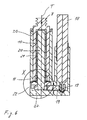
- FIG. 6 shows, in a longitudinal section, a bearing body 30 mounted as in the first embodiment, with the components of an administration device according to a second exemplary embodiment, which is likewise an infusion device.
- Those components of the second embodiment which are comparable in function and in part also in construction with components of the first embodiment, bear the same reference numerals as in the first embodiment. Differences exist only as far as subsequently attention is drawn or from the figures itself results. It should apply to the first embodiment, as far as no obvious contradictions arise from this.
- the administering device of the second embodiment has a game reducing means only for eliminating or at least reducing the axial play between the rotary member 20 and the bearing body 30.
- the game reduction device axially clamps the rotary member 20 directly against the sensor carrier 37.
- the translation element 10 surrounds the rotary member 20.
- the translation member 10 and the rotary member 20 are threadedly engaged with each other.
- the rotary member 20 is provided over most of its axial length with an external thread 21 and the translation member 10 only at its rear with respect to the translation direction V end with an internal thread 11.
- the translation member 10 is guided axially linearly on the bearing body 30.
- a motor 18 preferably an electric stepper motor, rotatably drives the rotary member 20 about the axis of rotation and translation T via a spur gear having two meshing gears 19 in mesh.
- the rotary member 20 is provided for its drive at its rear end again with a peripheral externally toothed annular web 22 which is in a front engagement with the intermediate gear 19 of the spur gear for the rotary drive of the rotary member 20.
- the pivot bearing of the rotary member 20 is shown enlarged in Figure 7.
- the pivot bearing of the second embodiment is formed as a simple sliding bearing.
- the second support surface 32 of the sensor carrier 37 and the fourth support surface 24 of the rotary member 20 form a first sliding pair of the rotary bearing.
- the two support surfaces 32 and 24 are directly in sliding contact with each other.
- the second support surface 32 is formed at the rear end of the rotary member 20. From the sensor support 37 projects against her a short base, the end face of which forms the second support surface 24.
- the socket releases the rotary member 20 from the sensor carrier 37.
- the formation of a base allows a more precise production of the second support surface 32.
- the third support surface 23 is in the manner of the support surface 23 of the first embodiment formed, namely by the translational direction T facing front end face of the annular ridge 22.
- the axially facing first support surface 31 is formed by the bearing body 30.
- the support surfaces 31 and 23 are radially offset from each other, ie they are not exactly axially in alignment.
- the radial offset is bridged by a transmission body 40, in the embodiment a transmission ring, which is arranged between the support surfaces 31 and 23.
- the transfer body 40 forms on a front end side of the first support surface 31 axially in alignment opposite to a translational axis T and the rotary member 20 encircling front support surface 41 and at its rear side of the third support surface 23 axially in alignment opposite a rear support surface 43.
- the rear Supporting surface 43 is directly on abutting contact with the third support surface 23.
- an annular spring 50 is arranged, which is supported axially on both support surfaces 31 and 41 with an axial biasing force.
- the annular spring 50 is shown individually in FIG. It is circumferentially wavy and made of spring steel, for example. When installed, it supports itself with its wave crests and troughs alternately circumferentially on the first support surface 31 and the front support surface 41 of the transfer body 40 from. When compressed axially, it acts like a leaf spring.
- the transfer body 40 serves not only to balance the radial offset, but also to center the annular spring 40.
- the transfer body 40 is provided with a circumferential projection 42 at its front end, around its outer circumference the front support surface 41 axially recirculated a little way back.
- the annular spring 50 and the transfer body 40 form the game reduction device of the second embodiment by the transfer body 40 is axially movable relative to the bearing body 30. Preferably, it is guided axially linearly by the bearing body 30. In principle, however, it can be rotatable relative to the bearing body 30.
- the transfer body 40 basically with the rotary member 20th can be connected torsionally rigid, either by means of joint or by a one-piece design with the rotary member 20, it is preferred if the transfer body 40 is rotatably arranged as in the embodiment relative to the rotary member 20 and more preferably also axially movable. In this way, a further pair of sliding surfaces of the pivot bearing is formed by the support surfaces 23 and 43 sliding directly abutting one another.
- the annular spring 50 is thus advantageously kept free from rotational movements.
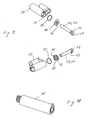
- Figure 9 shows an exploded view of the bearing body 30, the rotary member 20, the transfer body 40 and the annular spring 50 along the translation axis to be considered strung in a suitable sequence for the assembly.
- FIG. 10 shows the translation element 10 individually.
- the translation member 10 alone inserted from behind into the bearing body and then the rotary member 20 are screwed into the translation member 10, or it can first made the threaded connection between the translation member 10 and the rotary member 20 and only then the translation member 10 are inserted with the screwed rotary member 20 in the bearing body 30.
- the rotary member 20 of the transfer body 40 and the annular spring 50 are pushed over the external thread 21 up against the annular web 22 of the rotary member 20, and then the rotary member 20 is screwed into the translation member 10.
- the sensor carrier 37 With connected to the main body of the bearing body 30 shown in Figure 9, so that it closes open for the purpose of assembly back of the bearing body 30.
- Bearing body 30 and sensor carrier 37 are not movable relative to each other in the connected state.
- the connection is further designed so that the annular spring 50 is installed with a defined axial biasing force.
- the threaded engagement of the threads 11 and 21 is formed in the second embodiment as a simple threaded engagement, but may be formed axialspielredurophotened readily as in the first embodiment by means of an additional game reduction device.
- a Spielreduzier seen for the reduction or preferably elimination of axial play of the rotary bearing of the rotary member 20 may be formed as in the second embodiment and that conversely based on the adjustable adjustment engagement game reduction means 35 in the second embodiment instead of Game reduction device 40, 50 may be provided.
- Mixed forms are also conceivable.
- one of the roller bearings 27 and 28 could be arranged between one of the support surface pairs 31, 23 and 32, 24 or each such a roller bearing between two pairs of support surfaces, the one or both rolling bearings would preferably be arranged depending on the rolling bearings 27 and 28 of the first embodiment, ie it would act the ring spring 50 or an alternative spring only on one of the bearing shells such a rolling bearing.
- the bearing body 30 can be modified by dispensing with the axially movable mounting and the sensor 33 to a housing with a receptacle for a reservoir 12 and then serve directly as an enveloping structure as the enveloping structure of the first embodiment.
- Such an enveloping structure may be formed like conventional housings. Alternatively, however, it may have the thermal expansion properties of the support structure 2 of the first embodiment, so that reference is made to the relevant embodiments of the first embodiment.
Landscapes
- Health & Medical Sciences (AREA)
- Vascular Medicine (AREA)
- Engineering & Computer Science (AREA)
- Anesthesiology (AREA)
- Biomedical Technology (AREA)
- Heart & Thoracic Surgery (AREA)
- Hematology (AREA)
- Life Sciences & Earth Sciences (AREA)
- Animal Behavior & Ethology (AREA)
- General Health & Medical Sciences (AREA)
- Public Health (AREA)
- Veterinary Medicine (AREA)
- Infusion, Injection, And Reservoir Apparatuses (AREA)
- Medicinal Preparation (AREA)
Priority Applications (5)
| Application Number | Priority Date | Filing Date | Title |
|---|---|---|---|
| EP05006543A EP1704884B1 (fr) | 2005-03-24 | 2005-03-24 | Dispositif pour la distribution dosée d'un produit fluide |
| AT05006543T ATE413896T1 (de) | 2005-03-24 | 2005-03-24 | Vorrichtung für die dosierte verabreichung eines fluiden produkts |
| DE502005005948T DE502005005948D1 (de) | 2005-03-24 | 2005-03-24 | Vorrichtung für die dosierte Verabreichung eines fluiden Produkts |
| CA002539915A CA2539915A1 (fr) | 2005-03-24 | 2006-03-16 | Dispositif pour administration dosee d'un liquide |
| US11/388,187 US20060278112A1 (en) | 2005-03-24 | 2006-03-23 | Device for metered administration of a liquid product |
Applications Claiming Priority (1)
| Application Number | Priority Date | Filing Date | Title |
|---|---|---|---|
| EP05006543A EP1704884B1 (fr) | 2005-03-24 | 2005-03-24 | Dispositif pour la distribution dosée d'un produit fluide |
Publications (2)
| Publication Number | Publication Date |
|---|---|
| EP1704884A1 true EP1704884A1 (fr) | 2006-09-27 |
| EP1704884B1 EP1704884B1 (fr) | 2008-11-12 |
Family
ID=34934505
Family Applications (1)
| Application Number | Title | Priority Date | Filing Date |
|---|---|---|---|
| EP05006543A Expired - Lifetime EP1704884B1 (fr) | 2005-03-24 | 2005-03-24 | Dispositif pour la distribution dosée d'un produit fluide |
Country Status (5)
| Country | Link |
|---|---|
| US (1) | US20060278112A1 (fr) |
| EP (1) | EP1704884B1 (fr) |
| AT (1) | ATE413896T1 (fr) |
| CA (1) | CA2539915A1 (fr) |
| DE (1) | DE502005005948D1 (fr) |
Cited By (2)
| Publication number | Priority date | Publication date | Assignee | Title |
|---|---|---|---|---|
| WO2011064615A1 (fr) * | 2009-11-24 | 2011-06-03 | Tecres S.P.A. | Dispositif goutte-à-goutte pour fluides médicaux et autres |
| US9381305B2 (en) | 2009-03-31 | 2016-07-05 | Sanofi-Aventis Deutschland Gmbh | Medical device |
Families Citing this family (2)
| Publication number | Priority date | Publication date | Assignee | Title |
|---|---|---|---|---|
| DE10046279A1 (de) * | 2000-09-19 | 2002-04-04 | Disetronic Licensing Ag | Vorrichtung zur dosierten Verabreichung eines injizierbaren Produkts |
| DE102004059126B4 (de) * | 2004-12-08 | 2014-01-16 | Roche Diagnostics Gmbh | Adapter für Injektionsgerät |
Citations (8)
| Publication number | Priority date | Publication date | Assignee | Title |
|---|---|---|---|---|
| EP0514816A1 (fr) * | 1991-05-23 | 1992-11-25 | Ivac Corporation | Engagement dynamique d'un vis-ecrou avec détection d'engagement |
| DE4133402C1 (en) * | 1991-10-09 | 1993-01-07 | B. Braun Melsungen Ag, 3508 Melsungen, De | Medical pressure infusion appts. - has slidable holder pressing out syringe held in holder fixed to housing with selective motor or manual drive |
| US5492534A (en) * | 1990-04-02 | 1996-02-20 | Pharmetrix Corporation | Controlled release portable pump |
| DE19717107A1 (de) * | 1997-04-23 | 1998-11-05 | Disetronic Licensing Ag | Antriebsvorrichtung für einen Kolben in einem ein Medikamentfluid enthaltenden Behältnis |
| WO2001072357A2 (fr) * | 2000-03-29 | 2001-10-04 | Minimed, Inc. | Procedes et dispositifs ameliores servant a la detection de la puissance et de la pression fluidique d'une pompe a perfusion |
| US20040122366A1 (en) * | 2002-12-23 | 2004-06-24 | Farhad Kazemzadeh | Drug delivery apparatus |
| WO2004089448A1 (fr) * | 2003-04-11 | 2004-10-21 | Novo Nordisk A/S | Dispositif d'administration |
| EP1498150A1 (fr) * | 1994-09-02 | 2005-01-19 | Societe De Conseils De Recherches Et D'applications Scientifiques S.A.S. | Administration d'une composition medicamenteuse solide |
Family Cites Families (6)
| Publication number | Priority date | Publication date | Assignee | Title |
|---|---|---|---|---|
| DE3838465A1 (de) * | 1988-11-12 | 1990-05-17 | Fresenius Ag | Spritzenpumpe |
| DK175491D0 (da) * | 1991-10-18 | 1991-10-18 | Novo Nordisk As | Apparat |
| EP1257307A2 (fr) * | 1999-09-13 | 2002-11-20 | Vitro Diagnostics, Inc. | Entraineur de seringue multi-dose |
| US6478434B1 (en) * | 1999-11-09 | 2002-11-12 | Ball Aerospace & Technologies Corp. | Cryo micropositioner |
| ES2327731T3 (es) * | 2002-09-24 | 2009-11-03 | Shl Group Ab | Dispositivo de inyeccion. |
| US20050033232A1 (en) * | 2003-08-05 | 2005-02-10 | Kriesel Marshall S. | Infusion apparatus with modulated flow control |
-
2005
- 2005-03-24 AT AT05006543T patent/ATE413896T1/de not_active IP Right Cessation
- 2005-03-24 EP EP05006543A patent/EP1704884B1/fr not_active Expired - Lifetime
- 2005-03-24 DE DE502005005948T patent/DE502005005948D1/de not_active Expired - Lifetime
-
2006
- 2006-03-16 CA CA002539915A patent/CA2539915A1/fr not_active Abandoned
- 2006-03-23 US US11/388,187 patent/US20060278112A1/en not_active Abandoned
Patent Citations (8)
| Publication number | Priority date | Publication date | Assignee | Title |
|---|---|---|---|---|
| US5492534A (en) * | 1990-04-02 | 1996-02-20 | Pharmetrix Corporation | Controlled release portable pump |
| EP0514816A1 (fr) * | 1991-05-23 | 1992-11-25 | Ivac Corporation | Engagement dynamique d'un vis-ecrou avec détection d'engagement |
| DE4133402C1 (en) * | 1991-10-09 | 1993-01-07 | B. Braun Melsungen Ag, 3508 Melsungen, De | Medical pressure infusion appts. - has slidable holder pressing out syringe held in holder fixed to housing with selective motor or manual drive |
| EP1498150A1 (fr) * | 1994-09-02 | 2005-01-19 | Societe De Conseils De Recherches Et D'applications Scientifiques S.A.S. | Administration d'une composition medicamenteuse solide |
| DE19717107A1 (de) * | 1997-04-23 | 1998-11-05 | Disetronic Licensing Ag | Antriebsvorrichtung für einen Kolben in einem ein Medikamentfluid enthaltenden Behältnis |
| WO2001072357A2 (fr) * | 2000-03-29 | 2001-10-04 | Minimed, Inc. | Procedes et dispositifs ameliores servant a la detection de la puissance et de la pression fluidique d'une pompe a perfusion |
| US20040122366A1 (en) * | 2002-12-23 | 2004-06-24 | Farhad Kazemzadeh | Drug delivery apparatus |
| WO2004089448A1 (fr) * | 2003-04-11 | 2004-10-21 | Novo Nordisk A/S | Dispositif d'administration |
Cited By (2)
| Publication number | Priority date | Publication date | Assignee | Title |
|---|---|---|---|---|
| US9381305B2 (en) | 2009-03-31 | 2016-07-05 | Sanofi-Aventis Deutschland Gmbh | Medical device |
| WO2011064615A1 (fr) * | 2009-11-24 | 2011-06-03 | Tecres S.P.A. | Dispositif goutte-à-goutte pour fluides médicaux et autres |
Also Published As
| Publication number | Publication date |
|---|---|
| DE502005005948D1 (de) | 2008-12-24 |
| US20060278112A1 (en) | 2006-12-14 |
| CA2539915A1 (fr) | 2006-09-24 |
| EP1704884B1 (fr) | 2008-11-12 |
| ATE413896T1 (de) | 2008-11-15 |
Similar Documents
| Publication | Publication Date | Title |
|---|---|---|
| EP1704883B1 (fr) | Dispositif pour la distribution dosée d'un produit fluide | |
| EP1704886B1 (fr) | Dispositif pour la distribution dosée d'un produit fluide | |
| DE102005008280B3 (de) | Verabreichungsvorrichtung mit Anzeigetrommel | |
| EP0991440B1 (fr) | Dispositif d'entrainement pour un piston situe dans un contenant renfermant un medicament sous forme fluide | |
| EP1228777B1 (fr) | Dispositif d'injection | |
| EP1926514B1 (fr) | Dispositif d'injection à accouplement à glissement à deux voies | |
| EP2829292B1 (fr) | Dispositif d'entraînement et de dosage comprenant un élément de limitation pour empêcher le réglage d'une dose plus grande que disponible | |
| DE102005063497B4 (de) | Kunststofffeder | |
| EP2039382B1 (fr) | Ampoule dotée d'un joint en deux états de compression | |
| DE202009019077U1 (de) | Antriebsmechanismus für eine Medikamentenabgabevorrichtung und Medikamentenabgabevorrichtung | |
| EP2480272A2 (fr) | Appareil d'injection | |
| WO2009141005A1 (fr) | Dispositif d'administration d'un produit injectable comportant une indication de quantité résiduelle | |
| DE202011110857U1 (de) | Antriebsanordnung, Antriebskomponente und Arzneimittelabgabevorrichtung | |
| EP1704884B1 (fr) | Dispositif pour la distribution dosée d'un produit fluide | |
| WO2019016279A1 (fr) | Pompe volumétrique | |
| EP1704885A1 (fr) | Dispositif pour la distribution dosée d'un produit fluide | |
| EP1210136B1 (fr) | Dispositif d'administration d'un produit injectable | |
| EP1890750A1 (fr) | Compensation de longueur pour un dispositif de reglage d'un dispositif d'injection | |
| WO2001021235A1 (fr) | Dispositif pour administrer une dose d'un produit injectable | |
| EP1980283A1 (fr) | Réservoir de médicaments et dispositif destiné à la distribution automatisée d'un médicament liquide | |
| EP1364127B1 (fr) | Pompe a engrenages interieurs sans pieces intercalaires | |
| EP2014321B1 (fr) | Dispositif pour un appareil pour l'administration d'un produit | |
| DE102008058037B4 (de) | Kolben und Kolbenspritzenset | |
| CH710924A2 (de) | Dosierhülsen für Injektionsgerät. |
Legal Events
| Date | Code | Title | Description |
|---|---|---|---|
| PUAI | Public reference made under article 153(3) epc to a published international application that has entered the european phase |
Free format text: ORIGINAL CODE: 0009012 |
|
| AK | Designated contracting states |
Kind code of ref document: A1 Designated state(s): AT BE BG CH CY CZ DE DK EE ES FI FR GB GR HU IE IS IT LI LT LU MC NL PL PT RO SE SI SK TR |
|
| AX | Request for extension of the european patent |
Extension state: AL BA HR LV MK YU |
|
| 17P | Request for examination filed |
Effective date: 20061017 |
|
| AKX | Designation fees paid |
Designated state(s): AT BE BG CH CY CZ DE DK EE ES FI FR GB GR HU IE IS IT LI LT LU MC NL PL PT RO SE SI SK TR |
|
| 17Q | First examination report despatched |
Effective date: 20070615 |
|
| GRAP | Despatch of communication of intention to grant a patent |
Free format text: ORIGINAL CODE: EPIDOSNIGR1 |
|
| GRAS | Grant fee paid |
Free format text: ORIGINAL CODE: EPIDOSNIGR3 |
|
| GRAA | (expected) grant |
Free format text: ORIGINAL CODE: 0009210 |
|
| AK | Designated contracting states |
Kind code of ref document: B1 Designated state(s): AT BE BG CH CY CZ DE DK EE ES FI FR GB GR HU IE IS IT LI LT LU MC NL PL PT RO SE SI SK TR |
|
| REG | Reference to a national code |
Ref country code: GB Ref legal event code: FG4D Free format text: NOT ENGLISH |
|
| REG | Reference to a national code |
Ref country code: CH Ref legal event code: EP |
|
| RAP2 | Party data changed (patent owner data changed or rights of a patent transferred) |
Owner name: ROCHE DIAGNOSTICS GMBH Owner name: F. HOFFMANN-LA ROCHE AG |
|
| REG | Reference to a national code |
Ref country code: IE Ref legal event code: FG4D Free format text: LANGUAGE OF EP DOCUMENT: GERMAN |
|
| REF | Corresponds to: |
Ref document number: 502005005948 Country of ref document: DE Date of ref document: 20081224 Kind code of ref document: P |
|
| LTIE | Lt: invalidation of european patent or patent extension |
Effective date: 20081112 |
|
| PG25 | Lapsed in a contracting state [announced via postgrant information from national office to epo] |
Ref country code: ES Free format text: LAPSE BECAUSE OF FAILURE TO SUBMIT A TRANSLATION OF THE DESCRIPTION OR TO PAY THE FEE WITHIN THE PRESCRIBED TIME-LIMIT Effective date: 20090223 Ref country code: LT Free format text: LAPSE BECAUSE OF FAILURE TO SUBMIT A TRANSLATION OF THE DESCRIPTION OR TO PAY THE FEE WITHIN THE PRESCRIBED TIME-LIMIT Effective date: 20081112 |
|
| NLV1 | Nl: lapsed or annulled due to failure to fulfill the requirements of art. 29p and 29m of the patents act | ||
| PG25 | Lapsed in a contracting state [announced via postgrant information from national office to epo] |
Ref country code: SI Free format text: LAPSE BECAUSE OF FAILURE TO SUBMIT A TRANSLATION OF THE DESCRIPTION OR TO PAY THE FEE WITHIN THE PRESCRIBED TIME-LIMIT Effective date: 20081112 Ref country code: PL Free format text: LAPSE BECAUSE OF FAILURE TO SUBMIT A TRANSLATION OF THE DESCRIPTION OR TO PAY THE FEE WITHIN THE PRESCRIBED TIME-LIMIT Effective date: 20081112 Ref country code: IS Free format text: LAPSE BECAUSE OF FAILURE TO SUBMIT A TRANSLATION OF THE DESCRIPTION OR TO PAY THE FEE WITHIN THE PRESCRIBED TIME-LIMIT Effective date: 20090312 Ref country code: FI Free format text: LAPSE BECAUSE OF FAILURE TO SUBMIT A TRANSLATION OF THE DESCRIPTION OR TO PAY THE FEE WITHIN THE PRESCRIBED TIME-LIMIT Effective date: 20081112 Ref country code: NL Free format text: LAPSE BECAUSE OF FAILURE TO SUBMIT A TRANSLATION OF THE DESCRIPTION OR TO PAY THE FEE WITHIN THE PRESCRIBED TIME-LIMIT Effective date: 20081112 |
|
| REG | Reference to a national code |
Ref country code: IE Ref legal event code: FD4D |
|
| PG25 | Lapsed in a contracting state [announced via postgrant information from national office to epo] |
Ref country code: DK Free format text: LAPSE BECAUSE OF FAILURE TO SUBMIT A TRANSLATION OF THE DESCRIPTION OR TO PAY THE FEE WITHIN THE PRESCRIBED TIME-LIMIT Effective date: 20081112 Ref country code: BG Free format text: LAPSE BECAUSE OF FAILURE TO SUBMIT A TRANSLATION OF THE DESCRIPTION OR TO PAY THE FEE WITHIN THE PRESCRIBED TIME-LIMIT Effective date: 20090212 Ref country code: EE Free format text: LAPSE BECAUSE OF FAILURE TO SUBMIT A TRANSLATION OF THE DESCRIPTION OR TO PAY THE FEE WITHIN THE PRESCRIBED TIME-LIMIT Effective date: 20081112 Ref country code: IE Free format text: LAPSE BECAUSE OF FAILURE TO SUBMIT A TRANSLATION OF THE DESCRIPTION OR TO PAY THE FEE WITHIN THE PRESCRIBED TIME-LIMIT Effective date: 20081112 Ref country code: RO Free format text: LAPSE BECAUSE OF FAILURE TO SUBMIT A TRANSLATION OF THE DESCRIPTION OR TO PAY THE FEE WITHIN THE PRESCRIBED TIME-LIMIT Effective date: 20081112 |
|
| PG25 | Lapsed in a contracting state [announced via postgrant information from national office to epo] |
Ref country code: CZ Free format text: LAPSE BECAUSE OF FAILURE TO SUBMIT A TRANSLATION OF THE DESCRIPTION OR TO PAY THE FEE WITHIN THE PRESCRIBED TIME-LIMIT Effective date: 20081112 Ref country code: PT Free format text: LAPSE BECAUSE OF FAILURE TO SUBMIT A TRANSLATION OF THE DESCRIPTION OR TO PAY THE FEE WITHIN THE PRESCRIBED TIME-LIMIT Effective date: 20090413 Ref country code: SE Free format text: LAPSE BECAUSE OF FAILURE TO SUBMIT A TRANSLATION OF THE DESCRIPTION OR TO PAY THE FEE WITHIN THE PRESCRIBED TIME-LIMIT Effective date: 20090212 |
|
| PLBE | No opposition filed within time limit |
Free format text: ORIGINAL CODE: 0009261 |
|
| STAA | Information on the status of an ep patent application or granted ep patent |
Free format text: STATUS: NO OPPOSITION FILED WITHIN TIME LIMIT |
|
| BERE | Be: lapsed |
Owner name: DISETRONIC LICENSING A.G. Effective date: 20090331 |
|
| PG25 | Lapsed in a contracting state [announced via postgrant information from national office to epo] |
Ref country code: SK Free format text: LAPSE BECAUSE OF FAILURE TO SUBMIT A TRANSLATION OF THE DESCRIPTION OR TO PAY THE FEE WITHIN THE PRESCRIBED TIME-LIMIT Effective date: 20081112 |
|
| 26N | No opposition filed |
Effective date: 20090813 |
|
| PG25 | Lapsed in a contracting state [announced via postgrant information from national office to epo] |
Ref country code: MC Free format text: LAPSE BECAUSE OF NON-PAYMENT OF DUE FEES Effective date: 20090331 |
|
| REG | Reference to a national code |
Ref country code: CH Ref legal event code: PL |
|
| GBPC | Gb: european patent ceased through non-payment of renewal fee |
Effective date: 20090324 |
|
| REG | Reference to a national code |
Ref country code: FR Ref legal event code: ST Effective date: 20091130 |
|
| PG25 | Lapsed in a contracting state [announced via postgrant information from national office to epo] |
Ref country code: CH Free format text: LAPSE BECAUSE OF NON-PAYMENT OF DUE FEES Effective date: 20090331 Ref country code: LI Free format text: LAPSE BECAUSE OF NON-PAYMENT OF DUE FEES Effective date: 20090331 |
|
| PG25 | Lapsed in a contracting state [announced via postgrant information from national office to epo] |
Ref country code: BE Free format text: LAPSE BECAUSE OF NON-PAYMENT OF DUE FEES Effective date: 20090331 |
|
| PG25 | Lapsed in a contracting state [announced via postgrant information from national office to epo] |
Ref country code: FR Free format text: LAPSE BECAUSE OF NON-PAYMENT OF DUE FEES Effective date: 20091123 Ref country code: GB Free format text: LAPSE BECAUSE OF NON-PAYMENT OF DUE FEES Effective date: 20090324 |
|
| PG25 | Lapsed in a contracting state [announced via postgrant information from national office to epo] |
Ref country code: AT Free format text: LAPSE BECAUSE OF NON-PAYMENT OF DUE FEES Effective date: 20090324 |
|
| PG25 | Lapsed in a contracting state [announced via postgrant information from national office to epo] |
Ref country code: GR Free format text: LAPSE BECAUSE OF FAILURE TO SUBMIT A TRANSLATION OF THE DESCRIPTION OR TO PAY THE FEE WITHIN THE PRESCRIBED TIME-LIMIT Effective date: 20090213 |
|
| PG25 | Lapsed in a contracting state [announced via postgrant information from national office to epo] |
Ref country code: IT Free format text: LAPSE BECAUSE OF FAILURE TO SUBMIT A TRANSLATION OF THE DESCRIPTION OR TO PAY THE FEE WITHIN THE PRESCRIBED TIME-LIMIT Effective date: 20081112 |
|
| PG25 | Lapsed in a contracting state [announced via postgrant information from national office to epo] |
Ref country code: LU Free format text: LAPSE BECAUSE OF NON-PAYMENT OF DUE FEES Effective date: 20090324 |
|
| PG25 | Lapsed in a contracting state [announced via postgrant information from national office to epo] |
Ref country code: HU Free format text: LAPSE BECAUSE OF FAILURE TO SUBMIT A TRANSLATION OF THE DESCRIPTION OR TO PAY THE FEE WITHIN THE PRESCRIBED TIME-LIMIT Effective date: 20090513 |
|
| PG25 | Lapsed in a contracting state [announced via postgrant information from national office to epo] |
Ref country code: TR Free format text: LAPSE BECAUSE OF FAILURE TO SUBMIT A TRANSLATION OF THE DESCRIPTION OR TO PAY THE FEE WITHIN THE PRESCRIBED TIME-LIMIT Effective date: 20081112 |
|
| PG25 | Lapsed in a contracting state [announced via postgrant information from national office to epo] |
Ref country code: CY Free format text: LAPSE BECAUSE OF FAILURE TO SUBMIT A TRANSLATION OF THE DESCRIPTION OR TO PAY THE FEE WITHIN THE PRESCRIBED TIME-LIMIT Effective date: 20081112 |
|
| REG | Reference to a national code |
Ref country code: DE Ref legal event code: R082 Ref document number: 502005005948 Country of ref document: DE Ref country code: DE Ref legal event code: R081 Ref document number: 502005005948 Country of ref document: DE Owner name: ROCHE DIABETES CARE GMBH, DE Free format text: FORMER OWNER: ROCHE DIAGNOSTICS GMBH, 68305 MANNHEIM, DE |
|
| PGFP | Annual fee paid to national office [announced via postgrant information from national office to epo] |
Ref country code: DE Payment date: 20240220 Year of fee payment: 20 |
|
| REG | Reference to a national code |
Ref country code: DE Ref legal event code: R071 Ref document number: 502005005948 Country of ref document: DE |