EP0514854A2 - Dispositif de commande de l'air d'admission pour un moteur à combustion interne - Google Patents
Dispositif de commande de l'air d'admission pour un moteur à combustion interne Download PDFInfo
- Publication number
- EP0514854A2 EP0514854A2 EP92108487A EP92108487A EP0514854A2 EP 0514854 A2 EP0514854 A2 EP 0514854A2 EP 92108487 A EP92108487 A EP 92108487A EP 92108487 A EP92108487 A EP 92108487A EP 0514854 A2 EP0514854 A2 EP 0514854A2
- Authority
- EP
- European Patent Office
- Prior art keywords
- driving condition
- intake air
- passage
- engine speed
- downstream
- Prior art date
- Legal status (The legal status is an assumption and is not a legal conclusion. Google has not performed a legal analysis and makes no representation as to the accuracy of the status listed.)
- Granted
Links
Images


Classifications
-
- F—MECHANICAL ENGINEERING; LIGHTING; HEATING; WEAPONS; BLASTING
- F02—COMBUSTION ENGINES; HOT-GAS OR COMBUSTION-PRODUCT ENGINE PLANTS
- F02B—INTERNAL-COMBUSTION PISTON ENGINES; COMBUSTION ENGINES IN GENERAL
- F02B31/00—Modifying induction systems for imparting a rotation to the charge in the cylinder
- F02B31/04—Modifying induction systems for imparting a rotation to the charge in the cylinder by means within the induction channel, e.g. deflectors
- F02B31/06—Movable means, e.g. butterfly valves
-
- F—MECHANICAL ENGINEERING; LIGHTING; HEATING; WEAPONS; BLASTING
- F02—COMBUSTION ENGINES; HOT-GAS OR COMBUSTION-PRODUCT ENGINE PLANTS
- F02B—INTERNAL-COMBUSTION PISTON ENGINES; COMBUSTION ENGINES IN GENERAL
- F02B31/00—Modifying induction systems for imparting a rotation to the charge in the cylinder
- F02B31/08—Modifying induction systems for imparting a rotation to the charge in the cylinder having multiple air inlets
-
- F—MECHANICAL ENGINEERING; LIGHTING; HEATING; WEAPONS; BLASTING
- F02—COMBUSTION ENGINES; HOT-GAS OR COMBUSTION-PRODUCT ENGINE PLANTS
- F02B—INTERNAL-COMBUSTION PISTON ENGINES; COMBUSTION ENGINES IN GENERAL
- F02B31/00—Modifying induction systems for imparting a rotation to the charge in the cylinder
- F02B31/08—Modifying induction systems for imparting a rotation to the charge in the cylinder having multiple air inlets
- F02B31/085—Modifying induction systems for imparting a rotation to the charge in the cylinder having multiple air inlets having two inlet valves
-
- F—MECHANICAL ENGINEERING; LIGHTING; HEATING; WEAPONS; BLASTING
- F02—COMBUSTION ENGINES; HOT-GAS OR COMBUSTION-PRODUCT ENGINE PLANTS
- F02D—CONTROLLING COMBUSTION ENGINES
- F02D9/00—Controlling engines by throttling air or fuel-and-air induction conduits or exhaust conduits
- F02D9/02—Controlling engines by throttling air or fuel-and-air induction conduits or exhaust conduits concerning induction conduits
-
- F—MECHANICAL ENGINEERING; LIGHTING; HEATING; WEAPONS; BLASTING
- F02—COMBUSTION ENGINES; HOT-GAS OR COMBUSTION-PRODUCT ENGINE PLANTS
- F02D—CONTROLLING COMBUSTION ENGINES
- F02D9/00—Controlling engines by throttling air or fuel-and-air induction conduits or exhaust conduits
- F02D9/02—Controlling engines by throttling air or fuel-and-air induction conduits or exhaust conduits concerning induction conduits
- F02D2009/0201—Arrangements; Control features; Details thereof
- F02D2009/0274—Arrangements; Control features; Details thereof one being controlled by pressure in intake conduit, e.g. for slowly opening the throttle as the other valve is suddenly opened
-
- Y—GENERAL TAGGING OF NEW TECHNOLOGICAL DEVELOPMENTS; GENERAL TAGGING OF CROSS-SECTIONAL TECHNOLOGIES SPANNING OVER SEVERAL SECTIONS OF THE IPC; TECHNICAL SUBJECTS COVERED BY FORMER USPC CROSS-REFERENCE ART COLLECTIONS [XRACs] AND DIGESTS
- Y02—TECHNOLOGIES OR APPLICATIONS FOR MITIGATION OR ADAPTATION AGAINST CLIMATE CHANGE
- Y02T—CLIMATE CHANGE MITIGATION TECHNOLOGIES RELATED TO TRANSPORTATION
- Y02T10/00—Road transport of goods or passengers
- Y02T10/10—Internal combustion engine [ICE] based vehicles
- Y02T10/12—Improving ICE efficiencies
Definitions
- the present invention relates to an intake air control device for an internal combustion engine, the device comprising a reed valve passage for supplying intake air via reed valves, to thereby prevent a back flow of intake air, and a sub intake passage for creating a swirl in a combustion chamber.
- Japanese Unexamined Patent Publication No. 58-210322 discloses an intake air control device comprising a reed valve passage in which reed valves are arranged, and a sub intake passage, for creating a swirl in a combustion chamber, having a control valve and bypassing the reed valves.
- the sub intake passage when in a low engine speed and low engine load driving condition, the sub intake passage is opened by the control valve so that all of the intake air is supplied to the combustion chamber and passes through the sub intake passage, whereby a good combustion can be obtained by the creating of a swirl in the combustion chamber.
- the sub intake passage is closed by the control valve so that all of the intake air passes through the reed valve passage and is supplied to the combustion chamber, whereby a back flow of intake air is prevented by the reed valves and the control valve and it is possible to obtain a higher torque, to thus increase the charging efficiency.
- a large amount of intake air is required, and therefore in the above intake air control device, the intake air is supplied to and passes through the reed valve passage in this driving condition.
- the reed valves are relatively large and are arranged in a reed valve passage having a large cross section, but a considerable pressure loss is generated when the reed valves are fully open to allow a large amount of intake air to pass therethrough, and thus a desired torque cannot be obtained and a sufficient amount of intake air is not supplied to the combustion chamber, and accordingly, a considerable pressure loss occurs.
- an object of the present invention is to provide an intake air control device for an internal combustion engine, which device ensures that a sufficient amount of intake air is supplied during a high engine speed condition, and can maintain the same effect during a low engine speed condition.
- an intake air control device comprising: a main intake passage leading to a combustion chamber and allowing an amount of intake air required in a high engine speed driving condition to pass therethrough; a reed valve passage leading to the combustion chamber and having reed valves for allowing a sufficient amount of intake air required in a low engine speed and high engine load driving condition to pass therethrough only from upstream to downstream thereof; a sub intake passage leading to the combustion chamber for creating a swirl therein; detection means for detecting a current engine driving condition, all of the detected engine driving conditions being divided into a low engine speed and low engine load driving condition, a low engine speed and high engine load driving condition and high engine speed driving condition, each corresponding to a required amount of intake air; and selection means for selecting a passage through which the intake air is passed in response to said current engine driving condition, by selecting the sub intake passage when the current engine driving condition is a low engine speed and low engine load driving condition, selecting the reed valve passage when the current engine driving condition is a low engine
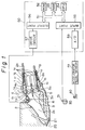
- Figure 1 shows a first embodiment of the present invention.
- reference numeral 1 designates a reed valve assembly having four side walls 1a, 1b, 1c, 1d (only 1d is not shown), defining an inside space 2a wherein a control valve 3 pivoting on a shaft 3a is mounted.
- Each of the side walls 1a, 1b, 1c, 1d is provided with a pair of openings 1e extending in a longitudinal direction upstream of the control valve 3, and a pair of reed valves 1f and stoppers 1g thereof are mounted at the each of the side walls 1a, 1b, 1c, 1d to cover the openings 1e and opening only outward therefrom.
- All of these reed valves 1f can allow an amount of intake air required during a low engine speed and high engine load driving condition to pass therethrough, because a longitudinal length of the reed valve assembly 1 can be freely selected and the reed valves 1f can be relatively large.
- a main intake passage 2 leading to a combustion chamber 20 via an intake valve 21 consists of the inside space 2a of the reed valve assembly 1, an upstream space 2b, and a downstream space 2c, and is formed so as to allow an amount of intake air required during a high engine speed driving condition to pass therethrough.
- a space 4a surrounding the reed valve assembly 1 called a reed valve passage 4 is communicated with the downstream space 2c, and intake air is passed therethrough via the reed valves 1f.
- a sub intake passage 5 for creating a swirl in the combustion chamber 20 communicates the inside space 2a downstream of the reed valves 1f with the downstream space 2c, at a point close to the intake valve 21.
- the control valve 3 closes the inside space 2c downstream of a opening 5a of the sub intake passage 5 formed in the lower side wall 1c, when in a first pivoted position as shown by a dotted line, and closes the inside space 2c upstream of the opening 5a when in a second pivoted position as shown by a chain line.
- the lower side wall 1c at a point close to the opening 5a and the upper side wall 1a at a point opposite to the opening 5a are provided with recess 1h, respectively, allowing the control valve 3 to be pivoted between the first pivoted position and the second pivoted position.
- a step motor 6 for driving the control valve 3 is mounted outside of the main intake passage 2, and is controlled by the electronic control unit (ECU) 50.
- the ECU 50 is constructed as a digital computer and includes a ROM (read only memory) 52, a RAM (random access memory) 53, a CPU (microprocessor, etc.) 54, an input port 55, and an output port 56.
- the ROM 52, the RAM 53, the CPU 54, the input port 55, and the output port 56 are interconnected by a bidirectional bus 51.
- a distributor 30 is provided with a crank angle sensor 31 connected to the input port 55.
- An accelerator pedal sensor 41 for detecting a degree of opening of an accelerator pedal 40 is also connected to the input port 55, via an AD converter 59.
- the output port 56 is connected to the step motor 6 via a drive circuit 57.
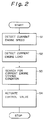
- the ECU 50 operates the control valve 3 according to a flow chart shown in Fig. 2.
- step S1 a current engine speed is detected on the basis of a signal from the crank angle sensor 31, and the routine goes to step S2.
- step S2 a current engine load is detected on the basis of a signal from the accelerator pedal sensor 41, and the routine goes to step S3.
- step S3 a search is made for a current engine driving condition, on the basis of the current engine speed and load, and the routine goes to step S4.
- step S4 the control valve 3 is actuated on the basis of the current engine driving condition.
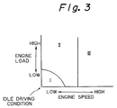
- the search at step S3 is carried out by using a first engine speed-load map shown in Fig. 3, in which all of the engine driving conditions are divided into three driving conditions I, II, and III corresponding to a required amount of intake air.
- the actuating at step S4 is carried out as follows.
- the control valve 3 When in the low engine speed and low engine load driving condition I, which includes an idling condition, the control valve 3 is pivoted by the step motor 6 to the first pivoted position (shown by the dotted line), whereby the control valve 3 serves as first closing means for closing the main intake passage 2 consisting of the inside space 2a of the reed valve assembly 1, the upstream space 2b and the downstream space 2c, between a branched point (the opening 5a) of the sub intake passage 5 and a merging point (an opening of the sub intake passage 5 leading to the downstream space 2c). Accordingly, almost the entire amount of intake air passes through the sub intake passage 5, and thus a good combustion can be obtained by a swirl created thereby in the combustion chamber 20.
- control valve 3 When in the low engine speed and high engine load driving condition II, the control valve 3 is pivoted by the step motor 6 to the second pivoted position (shown by the chain line), whereby the control valve 3 serves as second closing means for closing the main intake passage 2, between a branched point (the opening 1e in each of the side walls 1a, 1b, 1c, 1d of the reed valve assembly 1) of the reed valve passage 4 and a merging point (an opening of the passage 4 leading to the downstream space 2c), and upstream of the branched point of the sub intake passage 5.
- the entire amount of intake air passes, via the reed valves 1f, from the space 4a surrounding the reed valve assembly 1 to the downstream space 2c and is supplied to the combustion chamber 20, whereby a back flow of intake air is prevented by the control valve 3 and the reed valves 1f, and accordingly, the charging efficiency is increased and a higher torque is obtained.
- control valve 3 When in the high engine speed driving condition III, the control valve 3 is pivoted by the step motor 6 to a third pivoted position as shown by the solid line, to open the main intake passage 2. Accordingly, a large amount of intake air required in this driving condition passes through the main intake passage 2 and is supplied to the combustion chamber 20, without passing through the reed valves 1f, to thereby ensure a sufficient supply thereof, and avoid a drop in the torque.
- the manufacturing costs thereof can be reduced because the single control valve 3 serves as both the first and the second closing means.
- Figure 4(A) shows a second embodiment; here only the difference between the first and second embodiments is explained, as follows.
- a reed valve assembly 1' is formed such that the control valve 3 and portions of each side walls 1a, 1b, 1c, 1d surrounding the valve 3 from the reed valve assembly 1 in the first embodiment are omitted.
- a space 4a surrounding the reed valve assembly 1' communicates a sub intake passage 5 via a portion 2'c of the downstream space 2c close to an inside space 2a of the reed valve assembly 1'.
- FIG. 4(B) shows an enlarged view of a control valve 3'.
- reference numeral 3'a designates a pivoting shaft arranged in the portion 2'c of the downstream space 2c.
- the control valve 3' is slidable mounted on a shaft of a bolt 3'b having a head and fixed in the pivoting shaft 3'a, and is biased toward the head by a spring 3'c inserted in the shaft of the bolt 3'b.
- the control valve 3' is movable toward the pivoting shaft 3'a against the spring 3'c, and is driven together with the pivoting shaft 3'a by a step motor 6 controlled by an ECU (not shown), such as the ECU 50 in the first embodiment, and can be pivoted between a first pivoted position as shown by the dotted line and a second pivoted position as shown by the chain line.
- ECU not shown
- the control valve 3' When in the low engine speed and low engine load driving condition I, which includes an idling condition, the control valve 3' is pivoted by the step motor 6 to the first pivoted position (shown by the dotted line), whereby the control valve 3' serves as third closing means for closing the main intake passage 2 consisting of the inside space 2a of the reed valve assembly 1', the upstream space 2b and the downstream space 2c containing the portion 2'c, between the branched point and the merging point of the sub intake passage 5, and downstream of the merging point of the reed valve passage 4.
- the control valve 3' When in the low engine speed and high engine load driving condition II, the control valve 3' is pivoted by the step motor 6 to the second pivoted position (shown by the chain line), whereby the control valve 3 serves as the second closing means for closing the main intake passage 2, between the branched point and the merging point of the reed valve passage 4, and upstream of the branched point of the sub intake passage 5.
- the control valve 3' When in the high engine speed driving condition III, the control valve 3' is pivoted by the step motor 6 to a third pivoted position as shown by the solid line, to thereby open the main intake passage 2. Accordingly, the second embodiment can obtain the same effects as the first embodiment.
- the reed valves 1f if a degree of stiffness of the reed valves 1f is too low, a part of intake air in the low engine speed and low engine load driving condition I is supplied via the reed valves 1f without passing through the sub intake passage 5, whereby the intended swirl becomes weak, and if the degree of stiffness is too high, the reed valves 1f provide a considerable resistance to intake air in the low engine speed and high engine load driving condition II, whereby the required amount of intake air cannot be supplied to the combustion chamber 20. Accordingly, the degree of stiffness of the reed valves 1f must be very carefully selected.
- FIG. 5 shows a third embodiment; here only the difference between the third and second embodiments is explained, as follows.
- the intake air control device of the third embodiment comprises first and second control valves 7 and 8, and two step motors 9 and 10 for driving the valves 7 and 8, respectively. These step motors 9 and 10 are connected to an output port 56 of an ECU 50' via corresponding drive circuits 57 and 58, and are controlled by the ECU 50'.
- the first control valve 7 closes the main intake passage 2 in the first pivoted position of the control valve 3' used in the second embodiment, and the second control valve 8 closes the main intake passage 2 in the second pivoted position of the control valve 3'. Accordingly, the first control valve 7 serves as the third closing means explained in the second embodiment, and the second control valve 8 serves as the second closing means explained in the second embodiment, whereby the third embodiment can obtain the same effects as the second embodiment.
- the first control valve 7 closes the main intake passage 2 between the branched point and the merging point of the sub intake passage 5, and downstream of the merging point of the reed valve passage 4, as the third closing means
- the second control valve 8 closes the main intake passage 2 between the branched point and the merging point of the reed valve passage 4, and upstream of the branched point of the sub intake passage 5, as a fourth closing means, whereby all of the intake air passes from the passage 4, via the reed valves 1''f, to the sub intake passage 5 and is supplied to the combustion chamber 20, so that a more stable combustion can be obtained by the creating of a swirl, and further, to prevent a back flow of exhaust gases by the reed valves 1''f and the second control valve 8.
- Figures 6(A) and 6(B) show a modification of the third embodiment, when an intake air control device is used in a engine having two intake valves.
- a main intake passage 2 is divided into two passages downstream of the first control valve 7, and intake air is fed to the combustion chamber 20 via two intake valves 21a and 21b.
- a sub intake passage 5 leads to the main intake passage 2 at a point close to the intake valve 21a.
- a fuel injector 60 has two injection holes for injecting fuel toward the two intake valves 21a and 22a, respectively, and accordingly, the amount of fuel to be injected can be divided into two, and thus an atomization thereof can be accelerated when the fuel collides with the back side of the intake valves 21a and 21b.
- a desired ratio of the air-fuel mixture in the combustion chamber 20 cannot be obtained in the low engine speed and low engine load driving condition, because the intake air in this driving condition passes only through the sub intake passage 5 and is supplied only via the intake valve 21a and there is less intake air flowing to the combustion chamber 20 via the other intake valve 21b, and thus an amount of fuel injected toward the another intake valve 21b is atomized but this atomized fuel does not easily flow in the combustion chamber 20.
- the injector 60 is arranged between the first control valve 7 and second control valve 8, and accordingly, the fuel injected under driving conditions other than the low engine speed and low engine load driving condition I is atomized by an impact thereof with the two intake valves 21a and 21b, respectively, and flows in the combustion chamber 20 together with the intake air, and the fuel in the low engine speed and low engine load driving condition I is atomized and collides with the first control valve 7, which is closed in this driving condition, and becomes a mixture having a desired air/fuel ratio before the intake air passes through the sub intake passage 5. Accordingly, a desired ratio of the mixture can be always obtained in the low engine speed and low engine load driving condition I.
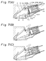
- FIG. 7 shows a fourth embodiment; here only the difference between the fourth and second embodiments is explained, as follows.
- a reed valve assembly 100 consists of an outside member 100A similar to the reed valve assembly 1' in the second embodiment and an inside member 100B joined telescopically to the outside member 100A.
- a control valve 11 is arranged at a part farthest downstream of an inside space 2d of the inside member 100B biased toward a downstream direction by a spring 12 with respect to the outside member 100A.
- the control valve 11 can pivot about a shaft 11a freely only in a anticlockwise direction in Fig. 7(A), and thus is suitably chamfered.
- a arm 13 mounted at a drive shaft 13a is arranged downstream of the control valve 11, and an end of the arm 13 bears against the control valve 11 at a point higher than the drive shaft 13a on Fig. 7(A).
- the drive shaft 13a is connected to a step motor 14 controlled by a ECU (not shown), such as the ECU 100 of the first embodiment.
- the arm 13 in the low engine speed and low engine load driving condition I, which includes the idling condition, the arm 13 is pivoted to a first pivoted position as shown in Fig. 6(A), and accordingly the control valve 11 serves as sixth closing means for closing the main intake passage 2 consisting of the inside spaces 2a and 2d of the reed valve assembly 100, the upstream space 2b and the downstream space 2c, between the branched point of the reed valve passage 4 and the merging point of the sub intake passage 5, and at the same time, the inside member 100B serves as fifth closing means for blocking the merging point of the reed valve passage 4 and the branched point of the sub intake passage 5 from the main intake passage 2 under a condition in which the reed valve passage 4 is communicated with the sub intake passage 5. Accordingly, all of the intake air passes from the reed valve passage 4, via the reed valves 100f, to the sub intake passage 5 and is supplied to the combustion chamber 20, and thus the same effects as in the third embodiment can be
- the arm 13 is pivoted in a clockwise direction to a second pivoted position, as shown in Fig. 7(B), so that the control valve 11 still closes the inside space 2d and the inside member 100B is slid in a upstream direction against the spring 12, and accordingly the merging point of the reed valve passage 4 is communicated with the downstream space 2c of the main intake passage 2.
- control valve 11 serves as the second closing means explained in the first embodiment, so that intake air is passed, via the reed valves 100f, through the main intake passage 2 and is supplied to the combustion chamber 20, whereby a higher torque can be obtained to thus increase the charging efficiency, as in the above-mentioned embodiments.
- the arm 13 is pivoted in a anti-clockwise direction to a third pivoted position, as shown in Fig. 7(C), so that the end of the arm 13 is separated from the control valve 11, and accordingly, the control valve 11 is opened by the force of the intake air, and thus the main intake passage 2 is opened and the intake air passes therethrough, to thereby ensure a sufficient supply thereof as in the above embodiments.
- the fourth embodiment can obtain the same effects as those of the third embodiment, and the manufacturing costs thereof can be reduced because only the step motor 14 for driving the arm 13 is used, in contrast to the third embodiment used the two step motors 9 and 10.
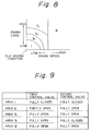
- the search at step S3 of the flow chart shown in Fig. 2 is carried out by using a second engine speed-load map as shown in figure 8, and then the actuating at step S4 is carried out in accordance with a table shown in Fig. 8, is explained.
- the low engine speed and high engine load driving condition II in the first map shown in Fig. 3 is divided into low engine speed and middle engine load driving conditions IIa, IIb, and low engine speed and high engine load driving condition IIc corresponding to a required amount of intake air.
- step S4 the first and second control valve 6 and 7 are opened in these driving conditions similar to the high engine speed driving condition III, to thereby reduce the fuel consumption because the greater compression force by the piston is not required.
- the first and second control valves 6 and 7 are in the same open or closed condition as mentioned above.
- the first control valve 6 is partly opened, corresponding to the required amount of intake air, and the second control valve 7 is fully opened so that a part of the required amount of intake air passes through the main intake passage 2 and the remainder of the required amount of intake air passes through the sub intake passage 5.
- the main intake passage 2 can be opened in the low engine speed and middle engine load driving condition IIa, IIb, as in the high engine speed driving condition III, whereby the fuel consumption at this time can be reduced.
- control valve 3 can be pivoted in a clockwise direction, corresponding to the required amount of intake air, from the first pivoted position, and in the second embodiment, the control valve 3' can be pivoted in an anti-clockwise direction, corresponding to the required amount of intake air, from the first pivoting position.
- the main intake passage 2 can be partly opened downstream of the branched point of the sub intake passage 5 and fully opened upstream of the control valve 3 or 3', in the low engine speed and middle engine load driving condition IIa in which a relatively small amount of intake air is required, whereby the fuel consumption at this time can be reduced and a good combustion can be obtained due to the swirl.
- the charging efficiency is increased to allow the required amount of intake air to be supplied via the reed valves, to thereby obtain a higher torque as usual, and in the high engine speed driving condition, a large required amount of intake air can be supplied through the main intake passage 2 without passing through the reed valves, to ensure a sufficient supply thereof.
- the intake air is supplied without passing through the reed valves, and accordingly, the fuel consumption at this time is reduced because the greater compressing force of the piston is not required.
- An intake air control device including a reed valve passage for supplying intake air via reed valves, and a sub intake passage for creating a swirl in the combustion chamber.
- the intake air control device further comprises a main intake passage for supplying intake air without passing same through the reed valves.
- a selection unit selects a passage through which the intake air is passed in response to a current engine driving condition, by selecting the sub intake passage when the current engine driving condition is a low engine speed and low engine load driving condition, selecting the reed valve passage when the current engine driving condition is a low engine speed and high engine load driving condition, and selecting the main intake passage when the current engine driving condition is a high engine speed driving condition.
Landscapes
- Engineering & Computer Science (AREA)
- Chemical & Material Sciences (AREA)
- Combustion & Propulsion (AREA)
- Mechanical Engineering (AREA)
- General Engineering & Computer Science (AREA)
- Characterised By The Charging Evacuation (AREA)
Applications Claiming Priority (4)
| Application Number | Priority Date | Filing Date | Title |
|---|---|---|---|
| JP11602391 | 1991-05-21 | ||
| JP116023/91 | 1991-05-21 | ||
| JP9371/92 | 1992-01-22 | ||
| JP4009371A JP2697448B2 (ja) | 1991-05-21 | 1992-01-22 | 内燃機関の吸気制御装置及び吸気制御方法 |
Publications (3)
| Publication Number | Publication Date |
|---|---|
| EP0514854A2 true EP0514854A2 (fr) | 1992-11-25 |
| EP0514854A3 EP0514854A3 (fr) | 1992-12-02 |
| EP0514854B1 EP0514854B1 (fr) | 1995-11-29 |
Family
ID=26344067
Family Applications (1)
| Application Number | Title | Priority Date | Filing Date |
|---|---|---|---|
| EP92108487A Expired - Lifetime EP0514854B1 (fr) | 1991-05-21 | 1992-05-20 | Dispositif de commande de l'air d'admission pour un moteur à combustion interne |
Country Status (4)
| Country | Link |
|---|---|
| US (1) | US5255648A (fr) |
| EP (1) | EP0514854B1 (fr) |
| JP (1) | JP2697448B2 (fr) |
| DE (1) | DE69206319T2 (fr) |
Cited By (6)
| Publication number | Priority date | Publication date | Assignee | Title |
|---|---|---|---|---|
| DE4311744A1 (de) * | 1993-04-08 | 1994-10-13 | Freudenberg Carl Fa | Ansaugrohr einer Verbrennungskraftmaschine |
| WO1999066180A1 (fr) * | 1998-06-13 | 1999-12-23 | Ford Global Technologies, Inc. | Systeme d'admission pour moteur |
| WO2000003131A1 (fr) * | 1998-07-08 | 2000-01-20 | Nonox B.V. | Dispositif de commande de charge et procede pour assurer la commande d'un moteur a combustion interne a piston alternatif |
| DE19735133B4 (de) * | 1996-08-29 | 2005-07-07 | General Motors Corp., Detroit | Ventilaufbau für einen Verbrennungsmotor |
| RU2275516C1 (ru) * | 2004-11-15 | 2006-04-27 | Общество с ограниченной ответственностью "Экотюнинг" | Впускной коллектор двигателя внутреннего сгорания |
| WO2007029104A2 (fr) | 2005-09-08 | 2007-03-15 | Toyota Jidosha Kabushiki Kaisha | Structure d'orifices d'admission pour moteur a combustion interne |
Families Citing this family (8)
| Publication number | Priority date | Publication date | Assignee | Title |
|---|---|---|---|---|
| US5533483A (en) * | 1995-05-04 | 1996-07-09 | Industrial Technology Research Institute | Engine air intake system having a bypass current control valve |
| DE19517079A1 (de) * | 1995-05-10 | 1996-11-14 | Bayerische Motoren Werke Ag | Luftansaugvorrichtung für Brennkraftmaschinen |
| JPH08326634A (ja) * | 1995-05-31 | 1996-12-10 | Sanshin Ind Co Ltd | 燃料噴射式エンジン |
| US5740778A (en) * | 1996-03-22 | 1998-04-21 | Ford Global Technologies, Inc. | Variable geometry intake system for an internal combustion engine |
| US5964201A (en) * | 1998-03-19 | 1999-10-12 | Ford Global Technologies, Inc. | Method for operating a multicylinder internal combustion engine and device for carrying out the method |
| DE19924397A1 (de) * | 1999-05-27 | 2000-11-30 | Bayerische Motoren Werke Ag | Ventilgesteuerte Brennkraftmaschine, insbesondere Otto-Brennkraftmaschine |
| JP3861789B2 (ja) * | 2002-10-03 | 2006-12-20 | 日産自動車株式会社 | 内燃機関の吸気装置 |
| US20160195008A1 (en) * | 2015-01-01 | 2016-07-07 | Cesar Mercier | Two-stroke opposed piston Rotary internal combustion engine with no reactive torque |
Family Cites Families (12)
| Publication number | Priority date | Publication date | Assignee | Title |
|---|---|---|---|---|
| JPS5627026A (en) * | 1979-08-09 | 1981-03-16 | Yamaha Motor Co Ltd | Suction device of engine |
| JPS58152123A (ja) * | 1982-03-06 | 1983-09-09 | Shuichi Kitamura | 内燃機関の吸気装置 |
| JPS58210322A (ja) * | 1982-06-02 | 1983-12-07 | Yamaha Motor Co Ltd | 内燃機関の吸気装置 |
| JPS59135334A (ja) * | 1983-01-24 | 1984-08-03 | Kawasaki Steel Corp | デジタル式張力測定装置 |
| IT1163075B (it) * | 1983-02-02 | 1987-04-08 | Alfa Romeo Auto Spa | Impianto di aspirazione per un motore a c.i.dotato di piu' valvole di aspirazione |
| JPS6158634A (ja) * | 1984-08-29 | 1986-03-25 | フクダ電子株式会社 | 生体用吸着型誘導電極 |
| JPS6174633A (ja) * | 1984-09-20 | 1986-04-16 | Amusetsuku:Kk | 粉粒体への液体添加方法及びその装置 |
| DE3622273A1 (de) * | 1986-07-03 | 1988-01-07 | Porsche Ag | Ansaugsystem fuer eine hubkolben-brennkraftmaschine |
| IT1216336B (it) * | 1986-11-11 | 1990-02-22 | Nicchio Ivano | Dispositivo di controllo del flusso dell aria aspirata per motori a combustione interna a quattro tempi |
| GB2242228A (en) * | 1990-03-24 | 1991-09-25 | Rover Group | I.c engine charge swirl inlet arrangement |
| US4986225A (en) * | 1990-06-08 | 1991-01-22 | General Motors Corporation | Intake reservoir system for an engine having a check valve |
| JPH04342825A (ja) * | 1991-05-21 | 1992-11-30 | Toyota Motor Corp | 内燃機関の吸気制御装置 |
-
1992
- 1992-01-22 JP JP4009371A patent/JP2697448B2/ja not_active Expired - Lifetime
- 1992-05-15 US US07/883,352 patent/US5255648A/en not_active Expired - Fee Related
- 1992-05-20 DE DE69206319T patent/DE69206319T2/de not_active Expired - Fee Related
- 1992-05-20 EP EP92108487A patent/EP0514854B1/fr not_active Expired - Lifetime
Cited By (10)
| Publication number | Priority date | Publication date | Assignee | Title |
|---|---|---|---|---|
| DE4311744A1 (de) * | 1993-04-08 | 1994-10-13 | Freudenberg Carl Fa | Ansaugrohr einer Verbrennungskraftmaschine |
| DE4311744C2 (de) * | 1993-04-08 | 2003-04-17 | Freudenberg Carl Kg | Ansaugrohr einer Verbrennungskraftmaschine |
| DE19735133B4 (de) * | 1996-08-29 | 2005-07-07 | General Motors Corp., Detroit | Ventilaufbau für einen Verbrennungsmotor |
| WO1999066180A1 (fr) * | 1998-06-13 | 1999-12-23 | Ford Global Technologies, Inc. | Systeme d'admission pour moteur |
| WO2000003131A1 (fr) * | 1998-07-08 | 2000-01-20 | Nonox B.V. | Dispositif de commande de charge et procede pour assurer la commande d'un moteur a combustion interne a piston alternatif |
| RU2275516C1 (ru) * | 2004-11-15 | 2006-04-27 | Общество с ограниченной ответственностью "Экотюнинг" | Впускной коллектор двигателя внутреннего сгорания |
| WO2006052166A3 (fr) * | 2004-11-15 | 2006-10-19 | Obshchestvo S Ogranichennoy Ot | Collecteur d'admission pour moteur a combustion interne |
| WO2007029104A2 (fr) | 2005-09-08 | 2007-03-15 | Toyota Jidosha Kabushiki Kaisha | Structure d'orifices d'admission pour moteur a combustion interne |
| WO2007029104A3 (fr) * | 2005-09-08 | 2007-05-03 | Toyota Motor Co Ltd | Structure d'orifices d'admission pour moteur a combustion interne |
| US7900595B2 (en) | 2005-09-08 | 2011-03-08 | Toyota Jidosha Kabushiki Kaisha | Intake port structure for internal combustion engine |
Also Published As
| Publication number | Publication date |
|---|---|
| DE69206319D1 (de) | 1996-01-11 |
| JPH0539725A (ja) | 1993-02-19 |
| JP2697448B2 (ja) | 1998-01-14 |
| EP0514854A3 (fr) | 1992-12-02 |
| EP0514854B1 (fr) | 1995-11-29 |
| US5255648A (en) | 1993-10-26 |
| DE69206319T2 (de) | 1996-05-02 |
Similar Documents
| Publication | Publication Date | Title |
|---|---|---|
| US5255648A (en) | Intake air control device for an internal combustion engine | |
| US4494506A (en) | Intake system for an internal combustion engine | |
| EP0160960B1 (fr) | Appareil de commande pour moteur à combustion interne | |
| US5325828A (en) | Air intake arrangement for internal combustion engine | |
| US4730587A (en) | Control device of an internal combustion engine | |
| JPH048610B2 (fr) | ||
| GB2270115A (en) | I.c. engine exhaust gas recirculation system. | |
| US5179917A (en) | Intake air control device for an internal combustion engine | |
| EP0887526B1 (fr) | Moteur à combustion à injection directe et circuit de refroidissement associé | |
| JPH10311231A (ja) | 内燃機関の出力制御装置 | |
| US5577487A (en) | Aircraft piston engine control system | |
| US5509397A (en) | Air supply system preventing backflow | |
| JPH0586913A (ja) | エンジンの吸気装置 | |
| JP2611979B2 (ja) | エンジンの吸気装置 | |
| JPS5828409B2 (ja) | セイソウキユウキシキナイネンキカン | |
| JPH0416605B2 (fr) | ||
| EP1705351B1 (fr) | Dispositif de contrôle d'un moteur multicylindre | |
| JPS58140453A (ja) | 空燃比制御装置 | |
| JPH1136898A (ja) | モータサイクルの電子燃料噴射制御装置 | |
| JP3073305B2 (ja) | 2サイクルエンジンの制御装置 | |
| JP2536936Y2 (ja) | 内燃機関の吸気制御装置 | |
| JP4037377B2 (ja) | 内燃機関 | |
| JPH0634581Y2 (ja) | 複吸気弁エンジン | |
| JPH0634578Y2 (ja) | 複吸気弁エンジン | |
| JPH05231164A (ja) | 排気タービン過給機付き内燃機関の過給圧制御装置 |
Legal Events
| Date | Code | Title | Description |
|---|---|---|---|
| PUAI | Public reference made under article 153(3) epc to a published international application that has entered the european phase |
Free format text: ORIGINAL CODE: 0009012 |
|
| PUAL | Search report despatched |
Free format text: ORIGINAL CODE: 0009013 |
|
| 17P | Request for examination filed |
Effective date: 19920520 |
|
| AK | Designated contracting states |
Kind code of ref document: A2 Designated state(s): DE GB |
|
| AK | Designated contracting states |
Kind code of ref document: A3 Designated state(s): DE GB |
|
| 17Q | First examination report despatched |
Effective date: 19930512 |
|
| GRAA | (expected) grant |
Free format text: ORIGINAL CODE: 0009210 |
|
| AK | Designated contracting states |
Kind code of ref document: B1 Designated state(s): DE GB |
|
| REF | Corresponds to: |
Ref document number: 69206319 Country of ref document: DE Date of ref document: 19960111 |
|
| PLBE | No opposition filed within time limit |
Free format text: ORIGINAL CODE: 0009261 |
|
| STAA | Information on the status of an ep patent application or granted ep patent |
Free format text: STATUS: NO OPPOSITION FILED WITHIN TIME LIMIT |
|
| 26N | No opposition filed | ||
| PGFP | Annual fee paid to national office [announced via postgrant information from national office to epo] |
Ref country code: GB Payment date: 19990519 Year of fee payment: 8 |
|
| PGFP | Annual fee paid to national office [announced via postgrant information from national office to epo] |
Ref country code: DE Payment date: 19990525 Year of fee payment: 8 |
|
| PG25 | Lapsed in a contracting state [announced via postgrant information from national office to epo] |
Ref country code: GB Free format text: LAPSE BECAUSE OF NON-PAYMENT OF DUE FEES Effective date: 20000520 |
|
| GBPC | Gb: european patent ceased through non-payment of renewal fee |
Effective date: 20000520 |
|
| PG25 | Lapsed in a contracting state [announced via postgrant information from national office to epo] |
Ref country code: DE Free format text: LAPSE BECAUSE OF NON-PAYMENT OF DUE FEES Effective date: 20010301 |