EP0514973A2 - Reflexionsfreie Verkleidungsschicht insbesondere für eine Elektronen strahlröhre - Google Patents
Reflexionsfreie Verkleidungsschicht insbesondere für eine Elektronen strahlröhre Download PDFInfo
- Publication number
- EP0514973A2 EP0514973A2 EP92201350A EP92201350A EP0514973A2 EP 0514973 A2 EP0514973 A2 EP 0514973A2 EP 92201350 A EP92201350 A EP 92201350A EP 92201350 A EP92201350 A EP 92201350A EP 0514973 A2 EP0514973 A2 EP 0514973A2
- Authority
- EP
- European Patent Office
- Prior art keywords
- coating layer
- gel
- degree
- substrate
- crosslinking
- Prior art date
- Legal status (The legal status is an assumption and is not a legal conclusion. Google has not performed a legal analysis and makes no representation as to the accuracy of the status listed.)
- Granted
Links
Images
Classifications
-
- H—ELECTRICITY
- H01—ELECTRIC ELEMENTS
- H01J—ELECTRIC DISCHARGE TUBES OR DISCHARGE LAMPS
- H01J29/00—Details of cathode-ray tubes or of electron-beam tubes of the types covered by group H01J31/00
- H01J29/86—Vessels; Containers; Vacuum locks
- H01J29/89—Optical or photographic arrangements structurally combined or co-operating with the vessel
- H01J29/896—Anti-reflection means, e.g. eliminating glare due to ambient light
-
- G—PHYSICS
- G02—OPTICS
- G02B—OPTICAL ELEMENTS, SYSTEMS OR APPARATUS
- G02B1/00—Optical elements characterised by the material of which they are made; Optical coatings for optical elements
- G02B1/10—Optical coatings produced by application to, or surface treatment of, optical elements
- G02B1/11—Anti-reflection coatings
- G02B1/113—Anti-reflection coatings using inorganic layer materials only
-
- H—ELECTRICITY
- H01—ELECTRIC ELEMENTS
- H01J—ELECTRIC DISCHARGE TUBES OR DISCHARGE LAMPS
- H01J2229/00—Details of cathode ray tubes or electron beam tubes
- H01J2229/89—Optical components associated with the vessel
- H01J2229/8913—Anti-reflection, anti-glare, viewing angle and contrast improving treatments or devices
- H01J2229/8918—Anti-reflection, anti-glare, viewing angle and contrast improving treatments or devices by using interference effects
Definitions
- the invention relates to an antireflective coating layer on a substrate, which coating layer has a refractive index gradient such that the refractive index decreases in the direction from the substrate surface to the outside surface of the coating layer, which coating layer consists of a gel.
- the invention also relates to a cathode ray tube comprising a display window having an antireflective coating layer.
- the invention further relates to a method of manufacturing an antireflective coating layer on a substrate, which coating layer has a refractive index gradient such that the refractive index decreases in the direction from the substrate surface to the outside surface of the coating layer, which coating layer consists of a gel which is formed by means of a reaction of an alkoxide starting material with water.
- Antireflective coating layers are used, for example, on display screens of display devices, on cover plates of solar collectors, on envelopes of light sources and on other optical elements such as lenses and windows, to reduce reflection losses of traversing light and to suppress disturbing reflections in images.
- a disadvantage of the known antireflective layer is that it is porous and, hence, mechanically weak. This disadvantage also occurs with other methods of rendering substrate surfaces antireflective, for example when the substrate is roughened by means of etching.
- a further disadvantage of the known method consists in the necessity to use a number of different solutions which are successively applied to the surface and which each require a drying step. Such a method comprises many steps and is unsuitable to be carried out as a continuous method.
- a particular object of the invention is to provide a cathode ray tube which is provided with such an improved antireflective layer.
- a further object of the invention is to provide a simple and efficacious method of manufacturing antireflective layers, which method must preferably be suitable to be carried out as a continuous method.
- an antireflective coating layer as described in the opening paragraph, which coating layer is a closed layer and the degree of crosslinking of the gel material increases in the direction from the substrate surface to the outside surface of the coating layer.
- a closed layer is to be understood to mean herein that the layer is not or substantially not porous as opposed to the known antireflective layer according to United States Patent Specification US 4830879.
- said coating layer consists of contiguous grains whose dimensions decrease in the direction from the substrate surface to the outside surface of the coating layer.
- Suitable gel materials for use in layers having a refractive index gradient are materials which can, for example, be manufactured with alkoxides of the M(OR) x type, where M is a metal atom such as Si, Al, Ti, where R is an alkyl group having 1 to 5 carbon atoms and where x is the valency of the metal atom, see United States Patent Specification US 4830879.
- the antireflective coating layer consists of a silica gel which, if desired, may comprise dopants.
- silica gel which can be manufactured by using alkoxysilanes as the starting material, provides a mechanically strong, temperature resistant layer having a low refractive index.
- the optical and other properties of the antireflective layer can be influenced by using dopants, see for example United States Patent Specification US 4830879.
- Oxides of chromium and/or aluminium can be used to influence the transmission properties of the layer.
- Metal particles can be used to increase the electric conductivity of the layer, as a result of which the layer may obtain an antistatic effect.
- the object of providing a cathode ray tube having an improved antireflective coating layer is achieved in that the coating layer consists of a non-porous gel, the degree of crosslinking of the gel material increasing in the direction from the surface of the display window to the outside surface of the coating layer, as a result of which the coating layer has a refractive index gradient such that the refractive index decreases in the direction from the surface of the display window to the outside surface of the coating layer.
- the object of providing a method of manufacturing an antireflective coating layer on a substrate is achieved by a method as described in the opening paragraph, in which an organic solution of the alkoxide starting material is provided on the substrate and converted into a gel in situ by means of a reaction with water, which gel is subsequently dried, and during the formation of the gel the reaction conditions are varied in such a manner that a non-porous gel is formed in which the degree of crosslinking of the gel material increases in the direction from the substrate surface to the outside surface of the coating layer.
- Short chain alcohols for example methanol and ethanol, or ketones can be used as the solvent of the organic solution, also see United States Patent Specification US 4830879.
- a layer having a refractive index with a regular variation and a layer having a low porosity and hence a low degree of light scattering are obtained according to a method in which the organic solution of the alkoxide starting material is atomized, preferably by using ultrasonic energy supply, after which the mist formed is brought into contact with the substrate surface to which the coating layer is applied.
- the increase of the degree of crosslinking is obtained by raising the temperature during the formation of the gel.
- linear chains are formed during the reaction with water, as a result of which a regular and compact structure having a high density and a high refractive index is formed.
- a relatively high temperature a greater degree of crosslinking takes place, which results in a less compact structure having a lower density and a lower refractive index.
- An additional effect is that at a relatively high temperature, there is less coalescence of the mist droplets and they dry more rapidly, thus forming smaller grains on the outside of the antireflective layer.
- Such layers have a particularly effective antireflective and antiglare effect.
- the degree of crosslinking of the gel can also be influenced in various other ways.
- the increase of the degree of crosslinking can be obtained by increasing the degree of acidity during the formation of the gel. In an acid medium, as at a low temperature, linear chains are formed, whereas in an alkaline medium an irregular network is formed.
- the increase of the degree of crosslinking can alternatively be obtained by reducing the concentration of the alkoxide starting material in the organic solution, which, as a side effect, causes the grain size (after the drying of the droplets) to decrease in the direction of the outside surface of the antireflective layer.
- the increase of the degree of crosslinking can also be attained by using alkoxide starting materials having an increasing degree of hydrolysis, in which process the composition of the material used can be varied continuously or in small steps.
- Suitable starting materials are alkoxysilanes of the formula Si(OR) 4-p (OH) p , where R is, for example, a methyl group or an ethyl group and where p has a value of 0 to 4.
- An increasing degree of hydrolysis corresponds to an increasing value of p.
- An additional advantage of the use of a mechanically strong antireflective layer according to the invention is formed by the fact that it has a reinforcing effect on the underlying substrate, as described per se in European Patent Application EP-A1-0294830.
- a mechanically strong antireflective layer according to the invention is formed by the fact that it has a reinforcing effect on the underlying substrate, as described per se in European Patent Application EP-A1-0294830.
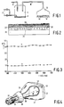
- Fig. 1 diagrammatically shows a device for carrying out the method according to the invention.
- Starting materials for the manufacture of an antireflective layer are supplied from storage containers which are not shown in the Figure via pipes 2, the quantities of each of the starting materials being separately controllable.
- the supply pipes 2 carry the liquid starting materials in drops to a nebulizer 4 which is provided with an ultrasonic element 6.
- a carrier gas can be supplied via a separate pipe 8, which carrier gas can be used to transport the mist to be formed via a transport pipe 10 to a deposition chamber 12. In said deposition chamber the mist is brought into contact with the substrate 14 to be coated which is placed on a heating plate 16.
- an alcoholic solution of an alkoxysilane and water with a small quantity of hydrochloric acid were used as the starting materials.
- the alcoholic solution consisted of ethanol with an alkoxysilane having the composition Si(OC2H5)(OH)3, where the molar ratio between ethanol and alkoxysilane was 13: 1.
- an acid for example hydrochloric acid or nitric acid may be added to the water, see United States Patent Specification US 4830879.
- a solution containing 10 ⁇ 3 M nitric acid was used. The ratio between the quantities of water and the alcoholic solution was selected such that 4 mol of water was present to 1 mol of the alkoxysilane.
- a polished glass plate was used as the substrate.
- the refractive index of the glass was 1.52, the reflection at a wavelength of 550 nm was 4.2%.
- the substrate was brought into contact with a mist as described hereinbefore, during which period the temperature of the substrate was gradually increased from an initial value of 23° C to a final value of 55°C.
- the layer was baked for 30 minutes at a temperature of 150° C.
- An antireflective layer having a thickness of 300 nm was provided. The layer thickness can be influenced according to the requirements by varying the duration of the deposition, by varying the concentration of the materials used, and by adjusting the gas flow and the mist flow, respectively.
- Fig. 2 shows a diagrammatic cross-sectional view of a substrate 20 having an antireflective layer 22.
- contiguous grains 28 can be recognized the dimension of which decreases in the direction from the polished substrate surface 24 to the outside surface 26.
- Fig. 3 shows the reflection R as a function of the wavelength of light, measured at the front of a glass plate without an antireflective layer (a), and with an antireflective layer as described hereinbefore (b).
- the substrate surface may be pretreated to ensure that the mist deposits on the surface as a continuous layer and not in the form of large drops.
- methods which are known per se can be used to render the substrate hydrophilic or hydrophobic in accordance with the composition and the hydrophilic/hydrophobic character of the material to be applied.
- Fig. 4 diagrammatically shows a cathode ray tube with a glass envelope 31, which is known per se , and which comprises a display window 32, a cone 33 and a neck 34.
- An electron gun 35 for generating an electron beam 36 is accommodated in the neck.
- Said electron beam 36 is focused to a spot 38 on a display screen 37.
- Said display screen is provided on the inside of the display window 32.
- the electron beam 36 is deflected across the display screen 37 in two mutually perpendicular directions x-y by means of the deflection coil system 39.
- a layer of a luminescing material (phosphor) is present on the display screen 37.
- the display window 32 is provided with an antireflective layer 40 on the outside, which antireflective layer was manufactured as described in exemplary embodiment 1.
- the method was carried out as described in exemplary embodiment 1, with this difference that the temperature was kept constant at a value of 30°C.
- the degree of acidity of the water added was reduced in small steps from 10 ⁇ 3 M to 10 ⁇ 4 M, thus causing the density of the layer manufactured to decrease gradually. Also in this case, there was a clear decrease of the reflection at the surface.
- the method was carried out as described in exemplary embodiment 1, with this difference that the temperature was kept constant at a value of 30° C.
- the alcoholic solution used was gradually diluted further with ethanol, the ratio between ethanol and alkoxysilane being gradually changed from 10: 1 to 25 : 1.
- the reflection decreased clearly and the structure of the antireflective layer was the same as shown in Fig. 2.
- the method was carried out as described in exemplary embodiment 1, with this difference that the temperature was kept constant at a value of 30° C.
- the temperature was kept constant at a value of 30° C.
- alkoxysilanes with an increasing degree of hydrolysis were used by varying the quantity of water added from an initial value of 1 : 1 to a final value of 4 : 1, expressed in the molar ratio of water relative to alkoxysilane.
- the reflection at the layer thus manufactured was less than 1.0%.
Landscapes
- Physics & Mathematics (AREA)
- Chemical & Material Sciences (AREA)
- Inorganic Chemistry (AREA)
- General Physics & Mathematics (AREA)
- Optics & Photonics (AREA)
- Surface Treatment Of Optical Elements (AREA)
- Vessels, Lead-In Wires, Accessory Apparatuses For Cathode-Ray Tubes (AREA)
- Surface Treatment Of Glass (AREA)
Priority Applications (1)
| Application Number | Priority Date | Filing Date | Title |
|---|---|---|---|
| EP92201350A EP0514973B1 (de) | 1991-05-21 | 1992-05-12 | Reflexionsfreie Verkleidungsschicht insbesondere für eine Elektronen strahlröhre |
Applications Claiming Priority (3)
| Application Number | Priority Date | Filing Date | Title |
|---|---|---|---|
| EP91201209 | 1991-05-21 | ||
| EP91201209 | 1991-05-21 | ||
| EP92201350A EP0514973B1 (de) | 1991-05-21 | 1992-05-12 | Reflexionsfreie Verkleidungsschicht insbesondere für eine Elektronen strahlröhre |
Publications (3)
| Publication Number | Publication Date |
|---|---|
| EP0514973A2 true EP0514973A2 (de) | 1992-11-25 |
| EP0514973A3 EP0514973A3 (en) | 1993-01-27 |
| EP0514973B1 EP0514973B1 (de) | 1998-08-26 |
Family
ID=26129266
Family Applications (1)
| Application Number | Title | Priority Date | Filing Date |
|---|---|---|---|
| EP92201350A Expired - Lifetime EP0514973B1 (de) | 1991-05-21 | 1992-05-12 | Reflexionsfreie Verkleidungsschicht insbesondere für eine Elektronen strahlröhre |
Country Status (1)
| Country | Link |
|---|---|
| EP (1) | EP0514973B1 (de) |
Cited By (5)
| Publication number | Priority date | Publication date | Assignee | Title |
|---|---|---|---|---|
| DE19642419A1 (de) * | 1996-10-14 | 1998-04-16 | Fraunhofer Ges Forschung | Verfahren und Beschichtungszusammensetzung zur Herstellung einer Antireflexionsbeschichtung |
| WO1998045113A1 (en) * | 1997-04-10 | 1998-10-15 | Corning Incorporated | Optical article with anti-reflecting coating, corresponding coating material and coating method |
| DE19828231C2 (de) * | 1997-08-16 | 2000-09-07 | Merck Patent Gmbh | Verfahren zur Abscheidung poröser optischer Schichten |
| US8414969B1 (en) | 2006-03-02 | 2013-04-09 | University Of Central Florida Research Foundation, Inc. | Sol-gel composite AR coating for IR applications |
| EP2517260A4 (de) * | 2009-12-22 | 2018-01-17 | AGC Flat Glass North America, Inc. | Antireflexionsbeschichtungen und verfahren zu ihrer herstellung |
Family Cites Families (2)
| Publication number | Priority date | Publication date | Assignee | Title |
|---|---|---|---|---|
| US4830879A (en) * | 1986-09-25 | 1989-05-16 | Battelle Memorial Institute | Broadband antireflective coating composition and method |
| EP0367269A3 (de) * | 1988-11-04 | 1991-11-13 | Asahi Glass Company Ltd. | Verfahren zum Verstärkung von Glas, filmerzeugende Zusammenstellung zur Verstärkung von Glas und Artikel aus verstärktem Glas |
-
1992
- 1992-05-12 EP EP92201350A patent/EP0514973B1/de not_active Expired - Lifetime
Cited By (6)
| Publication number | Priority date | Publication date | Assignee | Title |
|---|---|---|---|---|
| DE19642419A1 (de) * | 1996-10-14 | 1998-04-16 | Fraunhofer Ges Forschung | Verfahren und Beschichtungszusammensetzung zur Herstellung einer Antireflexionsbeschichtung |
| US6177131B1 (en) | 1996-10-14 | 2001-01-23 | Fraunhofer-Gesellschaft zur Förderung der angewandten Forschung e.V. | Method of making an anti-reflection coating |
| WO1998045113A1 (en) * | 1997-04-10 | 1998-10-15 | Corning Incorporated | Optical article with anti-reflecting coating, corresponding coating material and coating method |
| DE19828231C2 (de) * | 1997-08-16 | 2000-09-07 | Merck Patent Gmbh | Verfahren zur Abscheidung poröser optischer Schichten |
| US8414969B1 (en) | 2006-03-02 | 2013-04-09 | University Of Central Florida Research Foundation, Inc. | Sol-gel composite AR coating for IR applications |
| EP2517260A4 (de) * | 2009-12-22 | 2018-01-17 | AGC Flat Glass North America, Inc. | Antireflexionsbeschichtungen und verfahren zu ihrer herstellung |
Also Published As
| Publication number | Publication date |
|---|---|
| EP0514973A3 (en) | 1993-01-27 |
| EP0514973B1 (de) | 1998-08-26 |
Similar Documents
| Publication | Publication Date | Title |
|---|---|---|
| US5254904A (en) | Antireflective coating layer in particular for a cathode ray tube | |
| US5413865A (en) | Water-repellent metal oxide film and method of forming same on glass substrate | |
| US6638630B2 (en) | Composition and method for a coating providing anti-reflective and anti-static properties | |
| JP4841782B2 (ja) | 低反射膜および太陽電池パネル | |
| JP3178009B2 (ja) | 反射防止体及びその利用装置 | |
| EP0597490B1 (de) | Reflektion verringernde Schicht und Verfahren für deren Herstellung auf einem Glassubstrat | |
| EP0866037B1 (de) | Mehrlagiger, wasserabweisender Film und Verfahren zu dessen Herstellung auf einem Glassubstrat | |
| US4271210A (en) | Method of forming transmissive, porous metal oxide optical layer of a vitreous substrate | |
| EP0193269B2 (de) | Beschichtungszusammensetzung auf Basis von Silica | |
| US5858526A (en) | Composite material with a high refractive index, process for producing said composite material and optically active material incorporating said composite material | |
| US5698266A (en) | Process for the production of thin coatings having optical and abrasion resistance properties | |
| US5612128A (en) | Ultra fine particles having uneven surfaces and treatment plate using same | |
| EP0533256B1 (de) | Antistatische Bekleidungsschicht insbesondere für eine Elektronenstrahlröhre | |
| US6387517B1 (en) | Inorganic polymer material with tantalic acid anhydride base, in particular with high refractive index, mechanically abrasionproof, method of manufacture, optical materials comprising such material | |
| JP2002180003A (ja) | 磨耗耐性のあるSiO2反射防止層用の水性コーティング溶液 | |
| US20040043210A1 (en) | Reflection reducing coating, base material and photoelectric transducer with the reflection reducing coating | |
| EP0514973B1 (de) | Reflexionsfreie Verkleidungsschicht insbesondere für eine Elektronen strahlröhre | |
| JPH08508582A (ja) | 光学特性および耐摩耗性を有する薄層被覆層の形成方法 | |
| Nostell et al. | Antireflection of glazings for solar energy applications | |
| Roos et al. | Tin-oxide-coated anodized aluminium selective absorber surfaces I. Preparation and characterization | |
| EP1074526A2 (de) | Verfahren zur Herstellung einer antireflektiven und ausgleichenden Schicht auf Glas/TLO-Substraten | |
| WO2022132080A1 (en) | Anti-reflective silica based temperable coating solution | |
| JPH05234538A (ja) | 特に陰極線管用の反射防止及び帯電防止コーティング及びその製造方法 | |
| JPH06139822A (ja) | 透明導電膜、低反射帯電防止膜およびこれらの製造方法 | |
| Belleville et al. | Sol-gel antireflective spin-coating process for large-size shielding windows |
Legal Events
| Date | Code | Title | Description |
|---|---|---|---|
| PUAI | Public reference made under article 153(3) epc to a published international application that has entered the european phase |
Free format text: ORIGINAL CODE: 0009012 |
|
| AK | Designated contracting states |
Kind code of ref document: A2 Designated state(s): DE FR GB |
|
| PUAL | Search report despatched |
Free format text: ORIGINAL CODE: 0009013 |
|
| AK | Designated contracting states |
Kind code of ref document: A3 Designated state(s): DE FR GB |
|
| 17P | Request for examination filed |
Effective date: 19930701 |
|
| 17Q | First examination report despatched |
Effective date: 19931029 |
|
| GRAG | Despatch of communication of intention to grant |
Free format text: ORIGINAL CODE: EPIDOS AGRA |
|
| GRAG | Despatch of communication of intention to grant |
Free format text: ORIGINAL CODE: EPIDOS AGRA |
|
| GRAH | Despatch of communication of intention to grant a patent |
Free format text: ORIGINAL CODE: EPIDOS IGRA |
|
| GRAH | Despatch of communication of intention to grant a patent |
Free format text: ORIGINAL CODE: EPIDOS IGRA |
|
| GRAA | (expected) grant |
Free format text: ORIGINAL CODE: 0009210 |
|
| AK | Designated contracting states |
Kind code of ref document: B1 Designated state(s): DE FR GB |
|
| RAP3 | Party data changed (applicant data changed or rights of an application transferred) |
Owner name: KONINKLIJKE PHILIPS ELECTRONICS N.V. |
|
| REF | Corresponds to: |
Ref document number: 69226722 Country of ref document: DE Date of ref document: 19981001 |
|
| ET | Fr: translation filed | ||
| PLBE | No opposition filed within time limit |
Free format text: ORIGINAL CODE: 0009261 |
|
| STAA | Information on the status of an ep patent application or granted ep patent |
Free format text: STATUS: NO OPPOSITION FILED WITHIN TIME LIMIT |
|
| 26N | No opposition filed | ||
| REG | Reference to a national code |
Ref country code: GB Ref legal event code: IF02 |
|
| REG | Reference to a national code |
Ref country code: FR Ref legal event code: D6 |
|
| REG | Reference to a national code |
Ref country code: GB Ref legal event code: 746 Effective date: 20021107 |
|
| PGFP | Annual fee paid to national office [announced via postgrant information from national office to epo] |
Ref country code: FR Payment date: 20030526 Year of fee payment: 12 |
|
| PGFP | Annual fee paid to national office [announced via postgrant information from national office to epo] |
Ref country code: GB Payment date: 20030529 Year of fee payment: 12 |
|
| PGFP | Annual fee paid to national office [announced via postgrant information from national office to epo] |
Ref country code: DE Payment date: 20030715 Year of fee payment: 12 |
|
| PG25 | Lapsed in a contracting state [announced via postgrant information from national office to epo] |
Ref country code: GB Free format text: LAPSE BECAUSE OF NON-PAYMENT OF DUE FEES Effective date: 20040512 |
|
| PG25 | Lapsed in a contracting state [announced via postgrant information from national office to epo] |
Ref country code: DE Free format text: LAPSE BECAUSE OF NON-PAYMENT OF DUE FEES Effective date: 20041201 |
|
| GBPC | Gb: european patent ceased through non-payment of renewal fee |
Effective date: 20040512 |
|
| PG25 | Lapsed in a contracting state [announced via postgrant information from national office to epo] |
Ref country code: FR Free format text: LAPSE BECAUSE OF NON-PAYMENT OF DUE FEES Effective date: 20050131 |
|
| REG | Reference to a national code |
Ref country code: FR Ref legal event code: ST |