EP0515032B1 - Dispositif verseur pour liquides visqueux - Google Patents
Dispositif verseur pour liquides visqueux Download PDFInfo
- Publication number
- EP0515032B1 EP0515032B1 EP92303454A EP92303454A EP0515032B1 EP 0515032 B1 EP0515032 B1 EP 0515032B1 EP 92303454 A EP92303454 A EP 92303454A EP 92303454 A EP92303454 A EP 92303454A EP 0515032 B1 EP0515032 B1 EP 0515032B1
- Authority
- EP
- European Patent Office
- Prior art keywords
- cover plate
- pouring
- lever
- pouring device
- spout
- Prior art date
- Legal status (The legal status is an assumption and is not a legal conclusion. Google has not performed a legal analysis and makes no representation as to the accuracy of the status listed.)
- Expired - Lifetime
Links
Images

Classifications
-
- B—PERFORMING OPERATIONS; TRANSPORTING
- B65—CONVEYING; PACKING; STORING; HANDLING THIN OR FILAMENTARY MATERIAL
- B65D—CONTAINERS FOR STORAGE OR TRANSPORT OF ARTICLES OR MATERIALS, e.g. BAGS, BARRELS, BOTTLES, BOXES, CANS, CARTONS, CRATES, DRUMS, JARS, TANKS, HOPPERS, FORWARDING CONTAINERS; ACCESSORIES, CLOSURES, OR FITTINGS THEREFOR; PACKAGING ELEMENTS; PACKAGES
- B65D45/00—Clamping or other pressure-applying devices for securing or retaining closure members
- B65D45/02—Clamping or other pressure-applying devices for securing or retaining closure members for applying axial pressure to engage closure with sealing surface
- B65D45/025—Closure members opened by lever action and maintained closed by spring action
Definitions
- This invention relates to a pouring device for pouring liquid suspensions (referred to herein collectively as liquids) and is especially useful for pouring liquids (for example, paints and paint components, especially waterborne paints), that tend to be viscous.
- liquids for example, paints and paint components, especially waterborne paints
- the paint manufacturer is faced increasingly with a demand from the public to supply paints in greater ranges of colours.
- decorative paints that is to say paints to the decoration of buildings
- professional specifiers and do-it-yourself enthusiasts call for access to a wide range of colours and finishes.
- motor vehicle refinishing that is to say the repainting of vehicles after crash repair and the respray of commercial vehicles in company livery, there is a call for access to a wide range of paint colours.
- the only practical way such calls can be met is for the paint manufacturer to provide a mixing scheme.
- a mixing scheme consists of a base paint (generally called a mixing basic), a collection of coloured tinters and other paint components and a recipe card. The tinters and other components are added to the base paint according to the recipe card to produce the required colour.
- tinters In the case of paints for motor vehicle re-spray it is usual for the tinters to be added by being poured by hand from individual containers, eg paint cans; of course, this operation needs to be carried out accurately to ensure that the exact colour required is obtained. Normally, this is achieved by placing a container partly filled with the base paint to a predetermined weight on scales and pouring the or each tinter required into the base colour container up to a weight prescribed by the recipe.
- a pouring device for this operation which is constructed out of metal and comprises a lid provided around its periphery with a number of rotatable locking levers by which it can be fitted and sealed onto a standard container of a single particular size (eg 1 litre or 21 ⁇ 2 litre round can) the lid being integral with a pouring spout.
- the mouth of the pouring spout is defined by a frontal lip and is normally closed by a cover plate having a mating face.
- the cover plate is either mounted on a pivot and biased downwardly into abutting contact with the frontal lip, or the cover plate is mounted to be moved in sliding contact along said frontal lip, and is biased to cover the spout.
- each tint container is tipped to a position in which the plane of the frontal lip is substantially vertical so that the tint liquid will separate cleanly from the lip.
- Such devices have proved efficient in use and, in particular, the seal provided by the metal cover plate on the spout has been effective due mainly to the rigidity of the metal components.
- the known constructions do not readily enable the device to be made in plastics material, due mainly to the difficulty in achieving an effective seal because of the inherent resilience of suitable plastics material. Furthermore, they cannot be used for a range of different sized standard containers.
- a container top is known from US-A-2272867 which has a pouring device in accordance with the preamble of claim 1 and designed for pouring a viscous liquid such as syrup.
- the pouring device comprises a spout having a frontal lip defining its mouth, a cover plate associated therewith which is mounted to pivot about an axis and biased into abutting closing contact with the mouth lip, and operating means for the cover plate.
- the frontal lip is extended rearwardly to provide an annular opening, an inner wall defining the annular opening tapering outwardly towards the mouth lip to provide an annular seat, and an abutting face of the cover plate being formed with a shaped wall adapted to fit snugly within and around said seat when closed.
- An object of the invention is to provide a pouring device generally of the kind discussed above having a construction which enables it to be produced from plastics material and provide accurate pouring in use.
- a further object of the invention is to provide a pouring device generally of said kind which can be used for a range of different sized and/or shaped containers.
- such a pouring device is substantially wholly provided by two components
- the operating means are in the form of a lever, which is formed integrally with said cover plate to provide one of said components, said lever extends oppositely to the cover plate relative to its pivot axis
- the spout is formed integrally with a support body to provide the other component
- the support body has connection means by which the device can be detachably and sealingly connected over an aperture in a liquid container to which it is to be fitted, said support body defining a passage for communicating with liquid in the container
- the pouring device being characterised in that the two components are formed from suitable plastics material and in that the base of the support body is elongate and extends laterally from said connection means beneath the lever whereby, when fitted to the liquid container, said base engages over an extended area of an adjacent container wall to provide a stable support and absorb loads applied by said lever to the wall during use.
- connection means may comprise a recess having a screw thread adapted to screw onto a threaded boss for the aperture, a threaded closure cap being provided for said boss when the pouring device is not fitted.
- pivot axis for said integral cover plate and lever is positioned close to the spout whereby the annular opening of said spout can be opened and closed via the cover plate by a rocking motion of said lever.
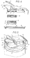
- the pouring device comprises essentially a support body 1 and a closure 2 providing a cover plate 3 and an operating lever 4 integrally formed therewith.
- the device is substantially wholly provided by two components which may conveniently be moulded from a suitable thermoplastics material, ie a material having a high degree of rigidity which is non-toxic and chemically resistant to the colour tints; suitable materials may be Polypropylene and Nylon, or filled plastics, for example Nylon filled with fibre glass.
- the support body 1 is formed with an elongate base 5 which defines a circular recess 6 (see Figure 2) provided with a screw thread 7 and the end wall 8 of this recess defines a shaped aperture 9 constituting a communicating passage which opens into a flared spout 10 upstanding from the base.
- the frontal lip 11 of the spout 10 is rounded as shown so as to be easy to clean.
- the support body has side walls 12 which are formed to provide shaped recesses to accomodate opposed side walls 13 of the closure 2.
- the side walls 13 of the closure are pivotally mounted on the side walls 9 of the body 1 via cooperating bearing holes through which a pivot pin 14 extends.
- connection between the closure 2 and support body 1 is such that the pivot axis provided by the pin 14 is close to the spout 10.
- the spout can be readily opened and closed via the cover plate 3 by a rocking motion of the lever 4.
- the cover plate 3 of the closure 2 is normally biased to its closed condition by a torsion spring which is wound around the pin 14 and has opposed straight ends 14A and 14B (see Figure 2) acting between the support body 1 and operating lever 4.
- the cover plate 3 of the closure 2 is rounded and dimensioned to mate with the lip 11 of the flared spout 10.
- the lip 11 in this embodiment (see particularly Figure 3) is angled as shown at 15 along its rearward extension. This angle is designed to present the frontal part of the lip in an advantageous orientation for efficient pouring i.e. so that the container does not need to be tipped completely into the horizontal plane to enable the plane of the lip to be substantially vertical during use. Also, the mating angle provided in the cover plate enhances the rigidity of this plate.
- the frontal lip 11 of the spout is extended rearwardly to produce an annular mouth opening 16 which is circular; the inner wall of the body 1 defining this mouth provides a circular seat 17 which tapers outwardly and upwardly to the mouth lip.
- the mating face of the cover plate 3 is provided with a projecting annular rib 18 having a tapered circular outer face which is dimensioned to fit snugly into and around the seat 17 when closed. In this manner, the spout 10 can be closed positively, the rib 18 cutting through the colour tint being poured and into engagement with its seat, thereby providing an abrupt cut-off to the flow. This enables accurate pouring to be achieved.
- the annular rib 18 provides further rigidity to the cover plate 2.
- the pouring device is adapted to be attached to a range of different colour tint paint containers, e.g. circular plastics cans of different diameters collapsible, bag-in-box type containers, shaped blow-moulded bottles, etc.
- the device is shown attached to the lid 19 of a known design of round plastics can.
- the lid is provided with an aperture 20 of a single, standard diameter into which is force fitted a collar 21 whereby a flange 22 on the collar is forced against the outer face of the lid; thus the flange acts to seal the aperture and to strengthen the lid around said aperture.
- the collar has a threaded boss 23 with a feathered edge 24 for sealing.
- the aperture in the lid is normally closed-off for storage and transportation by a cap 25. When the can is to be used, the cap is simply unscrewed and the pouring device fitted and sealed onto the boss via its threaded recess 6.
- the elongate base 5 of the pouring device has a shaped bottom edge so as to provide a pair of parallel projecting lugs 27.
- the lugs 27 bear on the surrounding flat area of the lid 19 between the boss and a circumferential lip 28 normally provided around the perimeter of the plastics lid.
- the elongate base 5 is in contact over a significant area of the lid and acts to provide a stable support and absorb loads applied to the lid when the lever 4 is operated during use.
- the lever 4 is of a significant width and its free end 29 is extended so that it projects clear of the can it is fitted to.
- the end of the lever 4 has a downwardly directed wall 30 to facilitate lifting of the can, particularly from a storage shelf, and handling of same.
Landscapes
- Engineering & Computer Science (AREA)
- Mechanical Engineering (AREA)
- Closures For Containers (AREA)
- Coating Apparatus (AREA)
- Nozzles (AREA)
- Details Of Rigid Or Semi-Rigid Containers (AREA)
- Medicines Containing Antibodies Or Antigens For Use As Internal Diagnostic Agents (AREA)
- Processing And Handling Of Plastics And Other Materials For Molding In General (AREA)
Claims (7)
- Dispositif verseur pour liquides visqueux du type comportant un bec verseur (10) possédant une lèvre avant (11) définissant son ouverture, une plaque de couverture (3) qui lui est associée et qui est montée pour pivoter autour d'un axe et est inclinée en aboutissant à un contact de fermeture avec la lèvre d'ouverture, et des moyens d'actionnement (4) destinés à la plaque de couverture, et dans lequel la lèvre avant (11) est étendue vers l'arrière afin de réaliser une ouverture annulaire (16), une paroi interne définissant l'ouverture annulaire se rétrécit vers l'extérieur en direction de la lèvre d'ouverture afin de réaliser un siège annulaire (17), et une face aboutissante de la plaque de couverture (3) est formée par une paroi formée (18) adaptée pour s'adapter parfaitement dans et sur ledit siège lorsqu'il est fermé, le dispositif étant sensiblement et complètement réalisé par deux composants, les moyens d'actionnement (4) étant sous la forme d'un levier qui est formé solidairement avec ladite plaque de couverture (3) afin de réaliser un desdits composants, ledit levier s'étendant en direction opposée à la plaque de couverture par rapport à l'axe du pivot, le bec (10) étant formé solidairement avec un corps de support (1) afin de réaliser l'autre composant, le corps de support ayant des moyens de connexion (6) à l'aide desquels le dispositif peut être connecté de façon détachable et hermétique par dessus une ouverture (20) dans un conteneur de liquide sur lequel il est à monter, ledit corps de support définissant un passage (9) offrant une communication pour le liquide dans le conteneur, caractérisé en ce que les deux composants sont formés à partir d'une matière plastique appropriée et en ce que l'embase (5) du corps de support est allongé et s'étend latéralement à partir desdits moyens de connexion sous le levier (4) si bien que, lorsque montée sur ledit conteneur de liquide, ladite embase s'engage au-dessus d'une zone étendue d'une paroi de conteneur adjacente (19) afin de réaliser un support stable et d'absorber les charges appliquées par ledit levier à la paroi durant l'utilisation.
- Dispositif verseur pour liquides visqueux selon la revendication 1, caractérisé en ce que les moyens de connexion (6) comportent un évidement dans ledit corps de support (1) comportant un filetage de vis (7) adapté pour être vissé sur un bossage fileté (23) destiné à l'ouverture (20), et en ce qu'un bouchon de fermeture fileté (25) est réalisé pour ledit bossage lorsque le dispositif verseur n'est pas monté dessus.
- Dispositif verseur pour liquides visqueux selon la revendication 2, caractérisé en ce que le bossage fileté (23) est réalisé par un collier (21) formant une partie du dispositif verseur adapté pour être situé dans l'ouverture (20) du conteneur sur lequel le dispositif est à monter, le collier comportant un rebord (22) qui est appuyé contre la face externe de la paroi du conteneur périphérique (19) afin de fermer hermétiquement ladite ouverture et de renforcer ladite paroi autour de ladite ouverture.
- Dispositif verseur pour liquides visqueux selon l'une quelconque des revendications précédentes, caractérisé en ce que l'axe du pivot destiné à ladite plaque de couverture solidaire (3) et au levier (4) est positionné à proximité du bec (10) si bien que l'ouverture annulaire (16) dudit bec peut être facilement ouverte et fermée via la plaque de couverture (3), par un mouvement de basculement dudit levier.
- Dispositif verseur pour liquides visqueux selon la revendication 4, caractérisé en ce que le levier (4) possède une largeur notable afin de permettre à l'utilisateur d'effectuer un mouvement de basculement alternatif en utilisant les doigts plutôt que le pouce d'une main, et en ce que l'extrémité libre dudit levier possède une paroi orientée vers le bas (30) afin de faciliter le levage et la manutention du conteneur sur lequel il est monté.
- Dispositif verseur pour liquides visqueux selon l'une queconque des revendications précédentes, caractérisé en ce que la lèvre avant (11) du bec (10) est inclinée de façon à présenter une orientation avantageuse destinée au versement, la plaque de couverture (3) ayant un angle d'accouplement renforçant la rigidité de ladite plaque.
- Dispositif verseur pour liquides visqueux selon l'une quelconque des revendications précédentes, caractérisé en ce que la paroi formée (18) prévue sur la plaque de couverture (3) destinée au montage dans et autour du siège annulaire (17), est réalisée par une face externe effilée d'une nervure annulaire (18) se projetant à partir de la face interne de ladite plaque de couverture, ladite nervure renforçant la rigidité de ladite plaque.
Applications Claiming Priority (2)
| Application Number | Priority Date | Filing Date | Title |
|---|---|---|---|
| GB919111022A GB9111022D0 (en) | 1991-05-22 | 1991-05-22 | Improvement relating to pouring devices for viscous liquid such as paint |
| GB9111022 | 1991-05-22 |
Publications (2)
| Publication Number | Publication Date |
|---|---|
| EP0515032A1 EP0515032A1 (fr) | 1992-11-25 |
| EP0515032B1 true EP0515032B1 (fr) | 1995-03-01 |
Family
ID=10695398
Family Applications (1)
| Application Number | Title | Priority Date | Filing Date |
|---|---|---|---|
| EP92303454A Expired - Lifetime EP0515032B1 (fr) | 1991-05-22 | 1992-04-16 | Dispositif verseur pour liquides visqueux |
Country Status (11)
| Country | Link |
|---|---|
| US (1) | US5267675A (fr) |
| EP (1) | EP0515032B1 (fr) |
| JP (1) | JP2577847B2 (fr) |
| AT (1) | ATE119121T1 (fr) |
| AU (1) | AU650528B2 (fr) |
| CA (1) | CA2069454C (fr) |
| DE (1) | DE69201517T2 (fr) |
| ES (1) | ES2069965T3 (fr) |
| GB (1) | GB9111022D0 (fr) |
| IE (1) | IE66525B1 (fr) |
| ZA (1) | ZA923042B (fr) |
Families Citing this family (25)
| Publication number | Priority date | Publication date | Assignee | Title |
|---|---|---|---|---|
| USD358915S (en) | 1994-07-25 | 1995-05-30 | O'donoghue John P | Pouring attachment for paint containers |
| USD398233S (en) | 1995-03-01 | 1998-09-15 | Wood C Deane Williams | Snap-on pour spout for cans or bottles |
| AUPN971596A0 (en) * | 1996-05-08 | 1996-05-30 | Kelly-Woolford, De-Arnne | Protocol - the ultimate pourer |
| US5941427A (en) * | 1996-07-17 | 1999-08-24 | Speer; Roger D. | Liquid storage can |
| ES2153263B1 (es) * | 1997-11-06 | 2001-09-01 | Bericap Sa | Tapon vertedor para liquidos viscosos. |
| BR7802155U (pt) * | 1998-01-05 | 2000-02-29 | Rubbermaid Inc | Tampa para um recipiente de bebidas |
| FR2796621B1 (fr) * | 1999-07-19 | 2002-02-01 | Simone Rebboah | Boite de conditionnement de boissons |
| RU2002116662A (ru) * | 1999-11-25 | 2004-02-27 | Берикап С.А. (Es) | Пробка для разлива вязких жидкостей |
| IT1318452B1 (it) * | 2000-04-06 | 2003-08-25 | Fast S R L Ora Fast & Fluid Ma | Coperchio con beccuccio erogatore particolarmente studiato perbarattoli di vernice e simili. |
| DE60125852D1 (de) * | 2000-04-06 | 2007-02-22 | Fast & Fluid Man S R L | Abmessvorrichtung für den Deckel eines Wassereimers oder lösungsmittelhaltige Farbe |
| CA2449416C (fr) | 2001-04-18 | 2011-02-22 | Nottingham-Spirk Partners, Llc | Ensemble ameliore de recipient et couvercle plastiques |
| USD472145S1 (en) | 2001-08-14 | 2003-03-25 | Nottingham-Spirk Partners, Llc | Paint container lid |
| USD482974S1 (en) | 2001-08-14 | 2003-12-02 | Nsi Innovation Llp | Round paint container |
| USD473790S1 (en) | 2001-08-14 | 2003-04-29 | Nottingham-Spirk Partners, Llc | Paint container insert |
| USD482973S1 (en) | 2001-08-14 | 2003-12-02 | Nsi Innovation Llc | Square paint container |
| USD480973S1 (en) | 2001-08-14 | 2003-10-21 | Nsi Innovation Llp | Design for a round paint container |
| USD563228S1 (en) | 2001-08-14 | 2008-03-04 | The Sherwin-Williams Company | Container for coating materials |
| USD482975S1 (en) | 2001-08-14 | 2003-12-02 | Nsi Innovation Llc | Round paint container |
| WO2003051737A2 (fr) * | 2001-12-14 | 2003-06-26 | Apc Products Limited | Fermeture a bouchon a vis en deux parties |
| JP4647178B2 (ja) * | 2002-08-30 | 2011-03-09 | 株式会社吉野工業所 | 容器の蓋体 |
| US7306118B1 (en) * | 2003-07-25 | 2007-12-11 | Masterchem Industries Llc | Paint container |
| US8424704B2 (en) * | 2004-06-02 | 2013-04-23 | X-Pert Paint Mixing Systems, Inc. | Self-cleaning lid for a paint container fluid pour spout |
| FR2892097B1 (fr) | 2005-10-14 | 2008-01-04 | Thierry Claude Leon Garcia | Couvercle a usages multiples, notamment pour des liquides, notamment pour pot de peinture. |
| US8833586B2 (en) * | 2010-04-16 | 2014-09-16 | Runway Blue, Llc | Bottle closure with integrated flip top handle |
| CN106458352B (zh) * | 2014-05-28 | 2020-09-22 | 万通集团公司 | 用于柔性容器的配件 |
Family Cites Families (14)
| Publication number | Priority date | Publication date | Assignee | Title |
|---|---|---|---|---|
| US1814083A (en) * | 1928-08-30 | 1931-07-14 | Francis C Yingling | Pouring spout |
| US1845966A (en) * | 1929-09-05 | 1932-02-16 | Francis C Yingling | Universal pouring spout |
| US2272867A (en) * | 1939-05-08 | 1942-02-10 | A H Heisey & Company | Container top |
| US2886218A (en) * | 1957-03-26 | 1959-05-12 | Marcus William | Container cap |
| US3185358A (en) * | 1963-06-03 | 1965-05-25 | Arnold H Marler | Handle and pouring spout with attaching means |
| US3168226A (en) * | 1963-09-11 | 1965-02-02 | Gen Foods Corp | Separable dispenser top |
| US3212686A (en) * | 1964-06-22 | 1965-10-19 | Washburn Co | Dripless pitcher |
| JPS428384Y1 (fr) * | 1965-12-02 | 1967-05-01 | ||
| US3672547A (en) * | 1969-12-30 | 1972-06-27 | Robert L Kozlowski | Container with replaceable plug and pouring spout |
| JPS595954Y2 (ja) * | 1980-07-30 | 1984-02-23 | 東洋電装株式会社 | 点火コイルと点火プラグコ−ドの接続装置 |
| JPS6340754A (ja) * | 1986-08-05 | 1988-02-22 | 美州興産株式会社 | ノンスリツプタイルの製造法 |
| FR2603527B1 (fr) * | 1986-09-08 | 1989-04-21 | Sablons Fonderies Atel | Couvercle muni d'un verseur a debit variable, notamment sur les machines d'agitation |
| CA1280109C (fr) * | 1987-07-08 | 1991-02-12 | Laszlo Murzsa | Contenant pour melanger la peinture |
| DE3784731T2 (de) * | 1987-11-13 | 1993-10-14 | Fast Spa | Deckel mit Ausguss für Farbe und Lack. |
-
1991
- 1991-05-22 GB GB919111022A patent/GB9111022D0/en active Pending
-
1992
- 1992-04-16 DE DE69201517T patent/DE69201517T2/de not_active Expired - Fee Related
- 1992-04-16 AT AT92303454T patent/ATE119121T1/de not_active IP Right Cessation
- 1992-04-16 ES ES92303454T patent/ES2069965T3/es not_active Expired - Lifetime
- 1992-04-16 EP EP92303454A patent/EP0515032B1/fr not_active Expired - Lifetime
- 1992-04-21 AU AU14992/92A patent/AU650528B2/en not_active Ceased
- 1992-04-22 IE IE921282A patent/IE66525B1/en not_active IP Right Cessation
- 1992-04-27 ZA ZA923042A patent/ZA923042B/xx unknown
- 1992-04-30 JP JP4111035A patent/JP2577847B2/ja not_active Expired - Fee Related
- 1992-05-20 US US07/886,005 patent/US5267675A/en not_active Expired - Lifetime
- 1992-05-22 CA CA002069454A patent/CA2069454C/fr not_active Expired - Fee Related
Also Published As
| Publication number | Publication date |
|---|---|
| JP2577847B2 (ja) | 1997-02-05 |
| CA2069454A1 (fr) | 1992-11-23 |
| ES2069965T3 (es) | 1995-05-16 |
| US5267675A (en) | 1993-12-07 |
| IE921282A1 (en) | 1992-12-02 |
| ATE119121T1 (de) | 1995-03-15 |
| AU1499292A (en) | 1992-11-26 |
| ZA923042B (en) | 1993-04-28 |
| IE66525B1 (en) | 1996-01-10 |
| DE69201517D1 (de) | 1995-04-06 |
| AU650528B2 (en) | 1994-06-23 |
| DE69201517T2 (de) | 1995-07-13 |
| JPH05139455A (ja) | 1993-06-08 |
| CA2069454C (fr) | 1997-07-15 |
| GB9111022D0 (en) | 1991-07-17 |
| EP0515032A1 (fr) | 1992-11-25 |
Similar Documents
| Publication | Publication Date | Title |
|---|---|---|
| US5267675A (en) | Pouring devices for viscous liquid such as paint | |
| US4811870A (en) | Liquid container with rotatable spout | |
| US7703641B2 (en) | Storage and dispensing container for paint | |
| US4666065A (en) | Liquid measuring and pouring device | |
| US5042698A (en) | Easy pour spout | |
| US5605254A (en) | Ventilated directional dispensing cap | |
| US4742928A (en) | Dispensing closure with articulated flip-top cap | |
| CA2067232C (fr) | Contenant distributeur | |
| US7040509B2 (en) | Container for liquids, including sealing mechanisms | |
| AU607375B2 (en) | Dispensing container closure | |
| US5118014A (en) | Spill-proof mug | |
| US5139182A (en) | Closure and dispensing device for containers | |
| US5358153A (en) | Mixing lid including a pouring device for containers used on stirring machines | |
| US4047648A (en) | Spout with snap acting cover and drain hole | |
| CN1049829A (zh) | 带有自密封阀的底部卸料的容器 | |
| US4832219A (en) | Dual dispensing hinged closure | |
| US5000360A (en) | Pouring spout which can be selectively opened and closed | |
| US3987943A (en) | Detachable pouring funnel for containers | |
| CA2144690A1 (fr) | Ouverture avec couvercle en position normalement ouverte | |
| CA2281536C (fr) | Dispositif de fermeture et de distribution | |
| US5630666A (en) | Cone-shaped paint container | |
| EP0701523B1 (fr) | Fermeture a disque basculant incolmatable | |
| WO2007070940A1 (fr) | Dispositif verseur coulissant actionné manuellement pour contenants | |
| JPS6238929Y2 (fr) | ||
| JPS6219560Y2 (fr) |
Legal Events
| Date | Code | Title | Description |
|---|---|---|---|
| PUAI | Public reference made under article 153(3) epc to a published international application that has entered the european phase |
Free format text: ORIGINAL CODE: 0009012 |
|
| AK | Designated contracting states |
Kind code of ref document: A1 Designated state(s): AT BE CH DE DK ES FR GB GR IT LI LU NL PT SE |
|
| 17P | Request for examination filed |
Effective date: 19930422 |
|
| 17Q | First examination report despatched |
Effective date: 19931119 |
|
| GRAA | (expected) grant |
Free format text: ORIGINAL CODE: 0009210 |
|
| AK | Designated contracting states |
Kind code of ref document: B1 Designated state(s): AT BE CH DE DK ES FR GB GR IT LI LU NL PT SE |
|
| PG25 | Lapsed in a contracting state [announced via postgrant information from national office to epo] |
Ref country code: GR Free format text: LAPSE BECAUSE OF FAILURE TO SUBMIT A TRANSLATION OF THE DESCRIPTION OR TO PAY THE FEE WITHIN THE PRESCRIBED TIME-LIMIT Effective date: 19950301 Ref country code: AT Effective date: 19950301 Ref country code: DK Effective date: 19950301 |
|
| REF | Corresponds to: |
Ref document number: 119121 Country of ref document: AT Date of ref document: 19950315 Kind code of ref document: T |
|
| ITF | It: translation for a ep patent filed | ||
| REF | Corresponds to: |
Ref document number: 69201517 Country of ref document: DE Date of ref document: 19950406 |
|
| ET | Fr: translation filed | ||
| PG25 | Lapsed in a contracting state [announced via postgrant information from national office to epo] |
Ref country code: LU Free format text: LAPSE BECAUSE OF NON-PAYMENT OF DUE FEES Effective date: 19950430 |
|
| REG | Reference to a national code |
Ref country code: ES Ref legal event code: FG2A Ref document number: 2069965 Country of ref document: ES Kind code of ref document: T3 |
|
| PG25 | Lapsed in a contracting state [announced via postgrant information from national office to epo] |
Ref country code: PT Effective date: 19950601 Ref country code: SE Effective date: 19950601 |
|
| PLBE | No opposition filed within time limit |
Free format text: ORIGINAL CODE: 0009261 |
|
| STAA | Information on the status of an ep patent application or granted ep patent |
Free format text: STATUS: NO OPPOSITION FILED WITHIN TIME LIMIT |
|
| 26N | No opposition filed | ||
| REG | Reference to a national code |
Ref country code: CH Ref legal event code: NV Representative=s name: DR. LUSUARDI AG Ref country code: CH Ref legal event code: PUE Owner name: IMPERIAL CHEMICAL INDUSTRIES PLC TRANSFER- PPG IND |
|
| NLS | Nl: assignments of ep-patents |
Owner name: PPG INDUSTRIES OHIO, INC. |
|
| REG | Reference to a national code |
Ref country code: FR Ref legal event code: TP |
|
| REG | Reference to a national code |
Ref country code: GB Ref legal event code: 732E |
|
| REG | Reference to a national code |
Ref country code: GB Ref legal event code: IF02 |
|
| PGFP | Annual fee paid to national office [announced via postgrant information from national office to epo] |
Ref country code: ES Payment date: 20090427 Year of fee payment: 18 |
|
| PGFP | Annual fee paid to national office [announced via postgrant information from national office to epo] |
Ref country code: DE Payment date: 20090429 Year of fee payment: 18 Ref country code: NL Payment date: 20090423 Year of fee payment: 18 Ref country code: IT Payment date: 20090429 Year of fee payment: 18 Ref country code: FR Payment date: 20090417 Year of fee payment: 18 |
|
| PGFP | Annual fee paid to national office [announced via postgrant information from national office to epo] |
Ref country code: BE Payment date: 20090528 Year of fee payment: 18 |
|
| PGFP | Annual fee paid to national office [announced via postgrant information from national office to epo] |
Ref country code: CH Payment date: 20090427 Year of fee payment: 18 |
|
| PGFP | Annual fee paid to national office [announced via postgrant information from national office to epo] |
Ref country code: GB Payment date: 20090429 Year of fee payment: 18 |
|
| BERE | Be: lapsed |
Owner name: *PPG INDUSTRIES OHIO INC. UNE SOCIETE DE L'ETAT DE Effective date: 20100430 |
|
| REG | Reference to a national code |
Ref country code: NL Ref legal event code: V1 Effective date: 20101101 |
|
| REG | Reference to a national code |
Ref country code: CH Ref legal event code: PL |
|
| GBPC | Gb: european patent ceased through non-payment of renewal fee |
Effective date: 20100416 |
|
| REG | Reference to a national code |
Ref country code: FR Ref legal event code: ST Effective date: 20101230 |
|
| PG25 | Lapsed in a contracting state [announced via postgrant information from national office to epo] |
Ref country code: NL Free format text: LAPSE BECAUSE OF NON-PAYMENT OF DUE FEES Effective date: 20101101 |
|
| PG25 | Lapsed in a contracting state [announced via postgrant information from national office to epo] |
Ref country code: LI Free format text: LAPSE BECAUSE OF NON-PAYMENT OF DUE FEES Effective date: 20100430 Ref country code: CH Free format text: LAPSE BECAUSE OF NON-PAYMENT OF DUE FEES Effective date: 20100430 Ref country code: DE Free format text: LAPSE BECAUSE OF NON-PAYMENT OF DUE FEES Effective date: 20101103 |
|
| PG25 | Lapsed in a contracting state [announced via postgrant information from national office to epo] |
Ref country code: IT Free format text: LAPSE BECAUSE OF NON-PAYMENT OF DUE FEES Effective date: 20100416 Ref country code: GB Free format text: LAPSE BECAUSE OF NON-PAYMENT OF DUE FEES Effective date: 20100416 Ref country code: BE Free format text: LAPSE BECAUSE OF NON-PAYMENT OF DUE FEES Effective date: 20100430 |
|
| REG | Reference to a national code |
Ref country code: ES Ref legal event code: FD2A Effective date: 20111118 |
|
| PG25 | Lapsed in a contracting state [announced via postgrant information from national office to epo] |
Ref country code: ES Free format text: LAPSE BECAUSE OF NON-PAYMENT OF DUE FEES Effective date: 20100417 |
|
| PG25 | Lapsed in a contracting state [announced via postgrant information from national office to epo] |
Ref country code: FR Free format text: LAPSE BECAUSE OF NON-PAYMENT OF DUE FEES Effective date: 20100430 |