EP0515101A2 - Puffersteuerung für einen Kanal mit variabler Bitrate - Google Patents
Puffersteuerung für einen Kanal mit variabler Bitrate Download PDFInfo
- Publication number
- EP0515101A2 EP0515101A2 EP92304377A EP92304377A EP0515101A2 EP 0515101 A2 EP0515101 A2 EP 0515101A2 EP 92304377 A EP92304377 A EP 92304377A EP 92304377 A EP92304377 A EP 92304377A EP 0515101 A2 EP0515101 A2 EP 0515101A2
- Authority
- EP
- European Patent Office
- Prior art keywords
- rate
- encoder
- channel
- buffer
- bit
- Prior art date
- Legal status (The legal status is an assumption and is not a legal conclusion. Google has not performed a legal analysis and makes no representation as to the accuracy of the status listed.)
- Granted
Links
Images




Classifications
-
- H—ELECTRICITY
- H04—ELECTRIC COMMUNICATION TECHNIQUE
- H04Q—SELECTING
- H04Q11/00—Selecting arrangements for multiplex systems
- H04Q11/04—Selecting arrangements for multiplex systems for time-division multiplexing
- H04Q11/0428—Integrated services digital network, i.e. systems for transmission of different types of digitised signals, e.g. speech, data, telecentral, television signals
- H04Q11/0478—Provisions for broadband connections
-
- H—ELECTRICITY
- H04—ELECTRIC COMMUNICATION TECHNIQUE
- H04N—PICTORIAL COMMUNICATION, e.g. TELEVISION
- H04N19/00—Methods or arrangements for coding, decoding, compressing or decompressing digital video signals
- H04N19/10—Methods or arrangements for coding, decoding, compressing or decompressing digital video signals using adaptive coding
- H04N19/134—Methods or arrangements for coding, decoding, compressing or decompressing digital video signals using adaptive coding characterised by the element, parameter or criterion affecting or controlling the adaptive coding
- H04N19/146—Data rate or code amount at the encoder output
-
- H—ELECTRICITY
- H04—ELECTRIC COMMUNICATION TECHNIQUE
- H04B—TRANSMISSION
- H04B14/00—Transmission systems not characterised by the medium used for transmission
- H04B14/02—Transmission systems not characterised by the medium used for transmission characterised by the use of pulse modulation
- H04B14/04—Transmission systems not characterised by the medium used for transmission characterised by the use of pulse modulation using pulse code modulation
-
- H—ELECTRICITY
- H04—ELECTRIC COMMUNICATION TECHNIQUE
- H04J—MULTIPLEX COMMUNICATION
- H04J3/00—Time-division multiplex systems
- H04J3/16—Time-division multiplex systems in which the time allocation to individual channels within a transmission cycle is variable, e.g. to accommodate varying complexity of signals, to vary number of channels transmitted
- H04J3/1682—Allocation of channels according to the instantaneous demands of the users, e.g. concentrated multiplexers, statistical multiplexers
- H04J3/1688—Allocation of channels according to the instantaneous demands of the users, e.g. concentrated multiplexers, statistical multiplexers the demands of the users being taken into account after redundancy removal, e.g. by predictive coding, by variable sampling
-
- H—ELECTRICITY
- H04—ELECTRIC COMMUNICATION TECHNIQUE
- H04L—TRANSMISSION OF DIGITAL INFORMATION, e.g. TELEGRAPHIC COMMUNICATION
- H04L65/00—Network arrangements, protocols or services for supporting real-time applications in data packet communication
- H04L65/40—Support for services or applications
-
- H—ELECTRICITY
- H04—ELECTRIC COMMUNICATION TECHNIQUE
- H04N—PICTORIAL COMMUNICATION, e.g. TELEVISION
- H04N19/00—Methods or arrangements for coding, decoding, compressing or decompressing digital video signals
- H04N19/10—Methods or arrangements for coding, decoding, compressing or decompressing digital video signals using adaptive coding
- H04N19/134—Methods or arrangements for coding, decoding, compressing or decompressing digital video signals using adaptive coding characterised by the element, parameter or criterion affecting or controlling the adaptive coding
- H04N19/146—Data rate or code amount at the encoder output
- H04N19/152—Data rate or code amount at the encoder output by measuring the fullness of the transmission buffer
-
- H—ELECTRICITY
- H04—ELECTRIC COMMUNICATION TECHNIQUE
- H04N—PICTORIAL COMMUNICATION, e.g. TELEVISION
- H04N21/00—Selective content distribution, e.g. interactive television or video on demand [VOD]
- H04N21/20—Servers specifically adapted for the distribution of content, e.g. VOD servers; Operations thereof
- H04N21/23—Processing of content or additional data; Elementary server operations; Server middleware
- H04N21/234—Processing of video elementary streams, e.g. splicing of video streams or manipulating encoded video stream scene graphs
- H04N21/23406—Processing of video elementary streams, e.g. splicing of video streams or manipulating encoded video stream scene graphs involving management of server-side video buffer
-
- H—ELECTRICITY
- H04—ELECTRIC COMMUNICATION TECHNIQUE
- H04N—PICTORIAL COMMUNICATION, e.g. TELEVISION
- H04N21/00—Selective content distribution, e.g. interactive television or video on demand [VOD]
- H04N21/20—Servers specifically adapted for the distribution of content, e.g. VOD servers; Operations thereof
- H04N21/23—Processing of content or additional data; Elementary server operations; Server middleware
- H04N21/236—Assembling of a multiplex stream, e.g. transport stream, by combining a video stream with other content or additional data, e.g. inserting a URL [Uniform Resource Locator] into a video stream, multiplexing software data into a video stream; Remultiplexing of multiplex streams; Insertion of stuffing bits into the multiplex stream, e.g. to obtain a constant bit-rate; Assembling of a packetised elementary stream
-
- H—ELECTRICITY
- H04—ELECTRIC COMMUNICATION TECHNIQUE
- H04N—PICTORIAL COMMUNICATION, e.g. TELEVISION
- H04N21/00—Selective content distribution, e.g. interactive television or video on demand [VOD]
- H04N21/20—Servers specifically adapted for the distribution of content, e.g. VOD servers; Operations thereof
- H04N21/23—Processing of content or additional data; Elementary server operations; Server middleware
- H04N21/24—Monitoring of processes or resources, e.g. monitoring of server load, available bandwidth, upstream requests
- H04N21/2401—Monitoring of the client buffer
-
- H—ELECTRICITY
- H04—ELECTRIC COMMUNICATION TECHNIQUE
- H04N—PICTORIAL COMMUNICATION, e.g. TELEVISION
- H04N21/00—Selective content distribution, e.g. interactive television or video on demand [VOD]
- H04N21/20—Servers specifically adapted for the distribution of content, e.g. VOD servers; Operations thereof
- H04N21/23—Processing of content or additional data; Elementary server operations; Server middleware
- H04N21/24—Monitoring of processes or resources, e.g. monitoring of server load, available bandwidth, upstream requests
- H04N21/2402—Monitoring of the downstream path of the transmission network, e.g. bandwidth available
-
- H—ELECTRICITY
- H04—ELECTRIC COMMUNICATION TECHNIQUE
- H04N—PICTORIAL COMMUNICATION, e.g. TELEVISION
- H04N21/00—Selective content distribution, e.g. interactive television or video on demand [VOD]
- H04N21/20—Servers specifically adapted for the distribution of content, e.g. VOD servers; Operations thereof
- H04N21/25—Management operations performed by the server for facilitating the content distribution or administrating data related to end-users or client devices, e.g. end-user or client device authentication, learning user preferences for recommending movies
- H04N21/266—Channel or content management, e.g. generation and management of keys and entitlement messages in a conditional access system, merging a VOD unicast channel into a multicast channel
- H04N21/2662—Controlling the complexity of the video stream, e.g. by scaling the resolution or bitrate of the video stream based on the client capabilities
-
- H—ELECTRICITY
- H04—ELECTRIC COMMUNICATION TECHNIQUE
- H04L—TRANSMISSION OF DIGITAL INFORMATION, e.g. TELEGRAPHIC COMMUNICATION
- H04L12/00—Data switching networks
- H04L12/54—Store-and-forward switching systems
- H04L12/56—Packet switching systems
- H04L12/5601—Transfer mode dependent, e.g. ATM
- H04L2012/5678—Traffic aspects, e.g. arbitration, load balancing, smoothing, buffer management
-
- H—ELECTRICITY
- H04—ELECTRIC COMMUNICATION TECHNIQUE
- H04N—PICTORIAL COMMUNICATION, e.g. TELEVISION
- H04N19/00—Methods or arrangements for coding, decoding, compressing or decompressing digital video signals
- H04N19/30—Methods or arrangements for coding, decoding, compressing or decompressing digital video signals using hierarchical techniques, e.g. scalability
-
- H—ELECTRICITY
- H04—ELECTRIC COMMUNICATION TECHNIQUE
- H04N—PICTORIAL COMMUNICATION, e.g. TELEVISION
- H04N19/00—Methods or arrangements for coding, decoding, compressing or decompressing digital video signals
- H04N19/50—Methods or arrangements for coding, decoding, compressing or decompressing digital video signals using predictive coding
Definitions
- This invention is related to video image processing and, more particularly, to avoiding encoder and decoder buffer overflow and underflow when the image is transmitted over a variable bit-rate channel.
- An encoder buffer is an essential element of this type of video coding system.
- the encoder buffer is used to translate the variable bit-rate signal supplied by an encoder to a constant bit-rate signal for transmission.
- a buffer/quantizer controller is often employed to regulate the buffer fullness by specifying the quantity of information that can be supplied to the encoder buffer by the encoder.
- Decoder buffer overflow occurs when the rate at which information is arriving from the channel is greater than the rate at which the decoder can process the information. Decoder buffer underflow occurs when the decoder buffer is empty and the decoder must display a new frame but no new frame has been decoded.
- B-ISDN Broadband Integrated Services Digital Networks
- An effectively variable bit-rate channel may arise for a particular signal when encoded signals are transmitted or stored together in a multiplexed fashion, e.g., encoded video that is multiplexed with associated audio signals and other bits, such as control bits, to form a single stored multiplexed bit-stream on a video disk.
- the compressed video signal data when extracted from the multiplexed bit-stream, typically becomes available in spurts such that the video data must be considered as arriving at a variable rate. This is true even when the multiplexed signal itself is being transmitted or recalled from storage at a constant bit-rate.
- the transmission bit-rate of such an effectively variable bit-rate channel is the rate that bits are removed from the encoder buffer associated with that channel.
- a prior solution for preventing buffer overflow and underflow in a decoder when an effectively variable bit-rate channel is employed requires the use of an additional buffer memory for interfacing to the variable bit-rate channel. Use of such an additional buffer is undesirable because of cost and other limitations it imposes on system configuration.
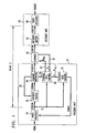
- FIG. 1 Shown in FIG. 1, in simplified block diagram form, is exemplary video encoder unit 15,variable bit-rate (rate) channel 30 and exemplary decoder unit 45 incorporating aspects of the invention.
- An original video signal, VIDIN that includes frames which contain at least one image representation, is supplied as an input to video encoder 10.
- Video encoder 10 produces bit-stream CODEIM, comprising frames, which contains a first encoded version of signal VIDIN.
- Each frame of bit-stream CODEIM contains an encoded version of the signals representing the images of a frame of signal VIDIN.
- Video encoders and methods employed to encode video signals are well known.
- Bit-stream CODEIM is stored in encoder buffer 20 from which it is supplied in a first in, first out (FIFO) fashion to channel interface 80.
- Channel interface 80 removes from bit-stream CODEIM a predetermined number of bits, which may be zero, and supplies as an output the rersulting second encoded version of signal VIDIN as bit-stream CODETR. Methods of arranging encoded video signals so that bits may be removed are well known. Thereafter, bit-stream CODETR is transmitted across variable rate channel 30 to decoder buffer 40.
- the number of bits to be removed from each frame of bit-stream CODEIM so as to produce bit-stream CODETR is determined by the difference between the actual bit-rate R, made available by variable rate channel 30 for transmitting the particularframe and a predicted value for that bit-rate, R re q which is requested from channel 30 via link 63 and that is expected to be available for trasmitting the particular frame. Only if R ⁇ R re q are any of the bits discarded. Such discarding of bits is to be regarded as an emergency measure that is to be undertaken only in the case of severe and unpredictable congestion of variable rate channel 30. It is a purpose of the invention to avoid any discarding of bits and any resulting loss of information. Therefore, in accordance with an aspect of the invention, control over the number of bits produced is exerted by video encoder 10.
- variable rate channel 30 itself might perform the removal of the bits, so that its output may not equal its input.
- channel interface 80 may only mark bits for deletion and the actual deletion of some or all bits is performed by channel 30 if it determines that the requested bit-rate cannot be made available.
- channel interface 80 may not be required and variable rate channel 30 can determine on its own which bits should be dropped from the format of bit-stream CODEIM.
- the bit-rate R is communicated to channel rate control 60 via link 67.
- Channel rate control 60 communicates the actual bit-rate to channel interface 80 via link 85.
- the predicted bit-rate is also supplied via link 85 to channel interface 80 which employs link 25 to retrieve from encoder buffer 20 bit-stream CODEIM at the requested rate R re q.
- link can be any form of communication interconnection apparatus, including, without limitation, serial transmission, parallel bus and shared memory.
- encoder buffer 20 may become empty, whereupon channel interface 80 immediately terminates transmission. In most cases, this will cause a reduction of R.
- variable rate channel 30 The bit-rates that can be supplied by variable rate channel 30 are not random, but are constrained in accordance with a predetermined function. Such channel constraint functions are well known, e.g., the leaky bucket function. Because of the constrained nature of variable rate channel 30, the granting of a particular requested bit-rate R re q can serve to impose limitations on the bit-rate that may be available to variable rate channel 30 for the granting of future requests. It is also noted that variable rate channel 30 may include a delay.
- variable rate channel 30 may be a video disk system.
- bit-stream CODETR is temporarily stored in decoder buffer 40.
- Bit-stream CODETR is supplied as an input to video decoder 50 from decoder buffer 40, in a first in, first out fashion.
- Video decoder 50 supplies as an output video signal VIDOUT, a reconstructed version of original video signal VIDIN.
- Video decoders and the techniques employed therein are well known in the art.
- Encoder buffer 20 and decoder buffer 40 each have predetermined fixed maximum sizes, B e max and B d max respectively, which are known to video encoder 10, channel rate control 60 and encoder rate control 70 a priori.
- the value of the delay factor L is known a priori by video encoder 10, channel rate control 60, encoder rate control 70 and decoder buffer 40.
- Encoder rate control unit 70 supplies to video encoder 10 signal RANGE.
- Signal RANGE is a representation of the range of acceptable numbers of bits that may be produced when encoding each frame of original video signal VIDIN into bit-stream CODEIM.
- the range constraining the number of bits that video encoder 10 may produce is determined so that neither encoder buffer 20 nor decoder buffer 40 will overflow or underflow. The method of determining this range will be described below.
- Video encoder 10 encodes each frame of signal VIDIN and thereby produces a portion of bit-stream CODEIM that represents frame i and actually contains E, bits in a frame period [(i-1) T, iT].
- E is a number that falls within the range given by the encoder rate control unit 70 in signal RANGE for frame i.
- the frame number index i designates each frame with respect to a predetermined starting frame.
- the E, bits, which are a portion of bit-stream CODEIM are supplied as an input to encoder buffer 20 and stored therein until it is time for them to be transmitted.
- a selection of a set of estimated channel bit-rates R i , R i+1 ,..., R i+L-1 by channel rate control unit 60 is controlled by the need to prevent encoder buffer 20 and decoder buffer40 from overflowing or underflowing.
- This selection is also controlled by the bit-rate constraint on variable rate channel 30, in accordance with an aspect of the invention.
- This bit-rate constraint on variable rate channel 30 may be time-varying.
- the cost of transmitting each bit is the cost of transmitting each bit and the fact that for some channel constraints (for example, the well known leaky bucket constraint) the channel bit-rate could be conserved at an earlier time so as to produce a less stringent channel rate constraint later. This might be desirable if a frame of original video signal VIDIN that has been encoded using intraframe techniques will need to be transmitted soon.
- some channel constraints for example, the well known leaky bucket constraint
- Channel rate control 60 supplies as an input the current estimated value of R, to variable rate channel 30 as a request for bit-rate R re q on line 63. If variable rate channel 30 grants the request for bit-rate, the actual channel bit-rate R, equal to R re q is returned on line 67. Otherwise, if variable rate channel 30 is unable to grant the request, the actual channel bit-rate granted R i , which is less than R re q is returned on line 67.
- Encoder rate control unit 70 receives as inputs the actual rate R, granted by variable rate channel 30 and the estimated potential future channel bit-rate values for the next L - 1 frames R i+L-1 ,..., R i+L-1 that are selected, in a manner to be described, from channel rate control unit 60. Encoder rate control unit 70 also receives as an input the actual number of bits E, that are supplied as an output by video encoder 10 for each frame period i. The range for E, that is supplied as an output by encoder rate control unit 70 is determined, in a manner to be described, such that neither encoder buffer 20 nor decoder buffer 40 will overflow or underflow.
- Channel rate control unit 60 also receives as an input the actual current channel bit-rate R i from channel 30 via link 67 and the number of bits E i that are actually supplied by video encoder 10 as an output in the current frame period.
- An estimated channel bit-rate R i+L which describes the number of bits that are desired to be transmitted across channel 30 in the frame period L frames hence, is selected by channel rate control unit 60.
- Each of these selected channel bit-rates are, as noted above, supplied as an input to encoder rate control unit 70.
- E(t) is defined to be the number of bits (or bytes or packets) output by the encoder at time t.
- the instantaneous bit-rate at any given time of variable rate channel 30, R(t), is variable.
- Be(t) and B d (t) are the instantaneous fullnesses of encoder and decoder buffers 20 and 40, respectively.
- Encoder buffer 20 and decoder buffer 40 each have predetermined fixed maximum sizes, Be max and B d max respectively.
- encoder unit 15 is designed to ensure that encoder buffer 20 never overflows, i.e., Conditions which are required to be placed on rates E i and R i to ensure that decoder buffer 40 never overflows or underflows, i.e., are described herein.
- decoder unit 45 After decoder unit 45 begins to receive data in decoder buffer 40, it waits LT seconds before starting to decode, as described above. Again, it is assumes for clarity purposes that L is an integer, although this is not necessary.
- a new time index ⁇ is defined for decoder unit 45. is zero when decoding begins. Therefore, where channel.delay is the transmission delay time across variable rate channel 30.
- the fullness of decoder buffer 40 varies depending on the channel bit-rate R(t) and the rate at which video decoder 50 extracts data from decoder buffer 40.
- encoder unit 15 determines that encoder buffer 20 is approaching fullness, the bit-rate of bit-stream CODEIM being supplied as an input by video coder 10 to encoder buffer 20 is reduced.
- Such a reduction in the bit-rate of bit-stream CODEIM may be achieved by reducing the quality of the encoding performed by video coder 10.
- One method of reducing the encoding quality is to employ a coarser quantization step size. Such methods of reducing encoding quality are well known in the art.
- video coder 10 can generate bit-stream CODEIM with a higher bit-rate, either by increasing the quality of encoding performed by video coder 10, or by supplying as an output stuffing bits that are consistent with the coding syntax and can be discarded by video decoder 50.
- the number of bits per frame can be unconstrained thereby yielding the following constraint on the channel bit-rate R I : which is the same as, for i > L where E i- L - Bd i-L-1 ⁇ R, specifies the condition in which underflow of decoder buffer 40 occurs and specifies the condition in which overflow of decoder buffer 40 occurs. Therefore, there is a restriction on the channel bit-rate R, that is dependent upon the output supplied by video encoder 10 L frames ago.
- a counter indicating the fullness of an imaginary buffer is maintained by variable rate channel 30 when it is constrained by a leaky-bucket function.
- R i bits for frame period i are supplied as an input to the imaginary buffer (henceforth called the "bucket" herein).
- the rate at which bits are supplied as an output from the bucket is R bits per frame period.
- the bucket size is N max .
- the instantaneous bucket fullness after frame i has been supplied to variable rate channel 30 is To ensure that high-priority are not dropped by channel interface 80, the rate R i must be such that the bucket never overflows, i.e., N i ⁇ N max , Vi, or Equation (19) defines the leaky-bucket constraint on the bit-rate that can be supplied as an input to variable rate channel 30.
- the leaky-bucket constraint is not the only constraint. In fact, preventing overflow of decoder buffer40 can impose a stronger constraint on the bit-rate that can be supplied as an input to variable rate channel 30. In particular, the right side of the decoder rate constraint specified in eq. (17) may be stricter than the leaky-bucket rate constraint of eq. (19).
- step 800 the routine is entered via step 800 upon the arrival of the first frame of original video signal VIDIN.
- R j may be also be desirable if the channel were a video disk so as to employ as few bits as possible.
- R j are chosen, they are chosen to be larger than the lower bound of eq. (20) to prevent decoder buffer underflow.
- decoder buffer 40 For i ⁇ L, no frames are yet being decoded by video decoder 50, and decoder buffer 40 is merely filling.
- the sum of R 1 ,..., R L should be chosen to exceed the expected bit-rate of the first few frames of bit-stream CODEIM in order to avoid underflow of decoder buffer 40.
- step 806 If the test result in step 806 is YES, control is passed to step 807, in which channel rate control 60 causes channel interface 80 to discard bits from bit-stream CODEIM in a selective fashion to yield signal CODETR. Channel interface 80 attempts to minimize any deleterious effects on the image within the frame that might result, in order to reduce the value of E i - L so as to satisfy the inequality of eq. (20) and thereby avoid a catastrophic underflow of decoder buffer 40. Control is then passed to step 808. Also, if the test result in step 806 is NO, indicating that underflow of decoder buffer 40 will not occur, control is passed to step 808.
- step 808 channel rate control 60 re-computes the estimates of rates for variable rate channel 30 for the leaky bucket fullnesses and fullnesses of decoder buffer 40 for the next L future frames of original video signal VIDIN using the actual (smaller) value of R. These new estimates are derived in the same manner as the estimates derived in step 802. Control is then passed to step 810.
- Step 810 estimates an upper bound (UB) on R i+L by using the leaky bucket constraint specified in eq. (21)
- an upper bound on E is determined by encoder rate control 70 in accordance with an aspect of the invention. This upper bound is determined by employing constraints on the overflow of encoder buffer 20 from inequality eq. (15) and underflow of decoder buffer 40 from inequality eq. (16) The minimum of these two upper bounds on E, is supplied as an output by encoder rate control 70 as signal RANGE to video encoder 10.
- Step 812 begins encoding of frame i by video encoder 10 subject to the bounds on E i and the transmission of a frame from encoder buffer 20 at rate R.
- step 813 the encoding of frame i by video encoder 10 and transmission through variable rate channel 30 of the frame supplied from encoder buffer 20 are completed.
- Video encoder 10 then supplies the actual value of E i as an input to channel rate control 60 and encoder rate control 70, in accordance with an aspect of the invention.
- the actual value of E i is used, in conditional branch point 814, to evaluate inequality eq. (14) and thereby determine if underflow of encoder buffer 20 occurred during the coding of frame i. If the test result in step 814 is NO, control is passed to step 816.
- step 814 If the test result in step 814 is YES, channel rate control 60 and channel interface 80 terminate transmission early, and control is passed to step 815 which calculates the new lower value of R i as Thereafter, control is passed to step 816.
- Step 816 uses actual values of E i and R i to compute actual values of B?, N i and Bd i-L using equations (8), (22) and (23), respectively.
- FIG. 2 Shown in FIG. 2 is exemplary encoding system 100 wherein a multiplicity of individual unencoded bit-streams 111-1 through 111-N are encoded and multiplexed into a single bit-stream 112 for transmission, in accordance with an aspect of the invention.
- the multiplexed bit-stream 112 is transmitted at constant rate R m
- the compressed versions of each bit stream when extracted from the multiplexed signal, typically becomes available in spurts such that each bit stream is considered as if it is arriving from a channel having a variable rate. Therefore, each bit stream is transported over an effectively variable bit-rate channel.
- a key characteristic of such an effectively variable bit-rate channel is that the portion of the total channel bandwidth that will be available to any access stream at any time is not known.
- Each of individual unencoded bit-streams 111 may be derived from a different source.
- Typical sources from which individual unencoded bit-streams 111 may be derived include, without limitation: video, audio and data.
- each of the parts of individual unencoded bit-streams 111 are associated together by virtue of having been generated during the same real time period.
- unencoded bit-stream 111-1 could be a series of frames that show a person speaking
- unencoded bit-stream 111-2 could be a series of audio frames containing a digitized representation of what was spoken.
- Each of unencoded bit-streams 111 are encoded by encoders 101 into encoded signals ENCOD.
- each portion of multiplexed stream 112 would contain a video frame and digitized representation of what was spoken by the speaker during the time interval of that associated video frame.
- each of individual encoded signals ENCOD has its own designated decoder and a corresponding decoder buffer, such as decoders 208 and decoder buffers 205.
- FIGS. 3 and 4 which shows another exemplary demultiplexer and decoder system
- there is no buffering of multiplexed stream 112 prior to its demultiplexing back into each of individual encoded signals ENCOD so that implementations may be developed that employ completely independent decoders.
- An advantage of such a system is that it permits easy intermixing of any number of video, audio, and other types of decoders into flexible configurations. Also, rate control can be provided for each of encoders 101 to prevent overflow and underflow of both encoder and decoder buffers.
- each of individual unencoded bit-streams 111-1 through 111-N are supplied as an input to one of encoders 101-1 through 101-N.
- unencoded bit-stream 111-1 is designated as a video signal and unencoded bit-stream 111-2 is designated as an audio signal.
- Each of encoders 101-1 through 101-N are adapted for encoding the type of information carried in the one of individual unencoded bit-streams 111 with which it is supplied and supplying as an output an encoded representation of the data carried therein as one of encoded bit-streams ENCOD-1 through ENCOD-N.
- each of encoders 101 are associated with one of encoder buffers 106-1 through 106-N.
- Each of encoder buffers 106 receives as an input and stores the one of encoded bit-streams ENCOD that was supplied from its associated one of encoders 101.
- the stored encoded bit-streams ENCOD are supplied from each of encoder buffers 106, in a first in, first out fashion, through multiplexer (mux) switch 108 to multiplex buffer 109 prior to transmission by the channel.
- Multiplex buffer 109 is typically much larger than each of encoder buffers 106 because it must be able to store data that has been supplied from each of encoder buffers 106.
- each of decoders 308 is able to have its own packets of data identified and extracted directly from the multiplexed bit-stream 112 by employing packet select units 301.
- An advantage of employing configurations such as those shown in FIGS. 3 and 4 is that additional decoders can be added, as desired, simply by connecting them to the multiplexed bit-stream 112 or demultiplexed individual encoded incoming data streams.
- Each of individual unencoded bit-streams 111 is assumed to consist of a sequence of "access units".
- a video access unit could be a video frame containing an image
- an audio access unit could be a block of digitized audio samples.
- Access units from unencoded bit-streams 111 are supplied to encoders 101 in which they are encoded and formed into one or more "packets" of data, which form each of signal ENCOD.
- packets For clarity of exposition, in this example there is assumed to be one packet per access unit. Other embodiments, included within the scope of the invention, in which the ratio of access units to packets is not unity, will be readily apparent to those skilled in the art.
- Each encoded packet contains a predetermined number of bits which may vary from packet to packet. The packets are supplied as an input to each of encoder buffers 106.
- the starting and ending times of each access unit are supplied from each of encoders 101 as input to each of encoder rate controllers 103 over links 102-1 through 102-N.
- the number of bits generated during the encoding of each access unit are supplied from each of encoders 101 as an input to each of encoder rate controllers 103 over links 102-1 through 102-N.
- Each of encoder rate controllers 103 monitors the starting and ending times of each access unit and the number of bits generated to encode each access unit.
- encoder rate controllers 103 supply to multiplex system controller 105, over links 104-1 through 104-N, the starting and ending times of each access unit and the number of bits generated.
- Multiplex system controller 105 employs the starting and ending times of each access unit and the number of bits generated in a manner described below.
- Encoder rate controllers 103 also monitor the fullness of buffers 106 in a manner to be described below for use in controlling the bit-rates of signals ENCODE that are supplied as outputs from encoders 101.
- packets that have been stored in encoder buffers 106 are gathered together to form "packs". This gathering is performed under the control of multiplex system controller 105, which commands mux switch 108 via link 107 to pass predetermined packets from predetermined ones of encoder buffers 106 to multiplexer buffer 109.
- the transfer of packets from encoder buffers 106 to multiplex buffer 109 is assumed to require only a fraction of a pack duration so that a subsequent pack can be coded without undue risk of encoder buffer overflow.
- the packs comprising the gathered packets are temporarily stored in multiplexer buffer 109 prior to their transmission to the channel.
- System timing is maintained by system clock 110 which supplies as an output a continuously increasing time valuer. It is used in several ways that are described below. Time values, i.e., particular values of ⁇ , may also be inserted periodically into multiplexed bit-stream 112 by multiplex buffer 109. These particular values of may be inserted in multiplexed bit-stream 112 at points which are left to the implementor's discretion. For purposes of this example, the particular values of are inserted as a part of the header data of each pack.
- the purpose of including particular values of ⁇ in multiplexed bit-stream 112 is to enable a similar system clock in the demultiplexing system, e.g., system clock 212 (FIG. 3) to accurately track system clock 110.
- exemplary demultiplexing and decoding system 200 packets of multiplex data stream 112, which are incoming from the channel, are identified as to which stream they belong to by switch controller 202. The packets are then switched to a corresponding one of decoder buffers 205-1 through 205-N by demultiplexer switch 203. This switching demultiplexes multiplex data stream 112 back into its original separate encoded signals ENCOD, which each comprise packets containing encoded access units.
- Demultiplexer switch 203 is controlled by switch controller 202 over link 204.
- the packets remain in decoder buffers 205 until their respective ones of decoders 208-1 through 208-N are ready to decode them.
- each decoder waits exactly LT seconds after arrival of the first bit of information from channel line 112 before starting to decode.
- L is a system parameter determined by the implementor, as discussed in connection with FIG. 1
- T is a pack duration described below.
- System clock 212 generates clock for decoder 200. Timing information, the insertion of which was discussed above, may also be extracted from multiplex data stream 112 by switch controller 202. When a system time value, i.e., a particular value of ⁇ , arrives in multiplex data stream 112, it is routed by demultiplexer switch 203 to system clock 212 and utilized to reset the system clock to the newly arrived value. Such timing information may be included in the data streams by encoders 101, to be used later by decoders 208 or 308 in further synchronization of audio, video and other data.
- demultiplexer and decoder 300 an alternative exemplary embodiment depicted in FIG. 4, packets of multiplex data stream 112, which are incoming from the channel, are supplied in parallel to packet selectors 301-1 through 301-N. Each of packet selectors 301 identifies which packets are a part of its associated data stream. Each packet so identified is selected and supplied to its associated one of decoder buffers 304 where they are stored awaiting decoding by one of decoders 308-1 through 308-N. In this embodiment, system timing from multiplex data stream 112 is supplied to each of decoders 308. Each of decoders 308 maintains their own independent system time clocks (not shown) that are the same as system clock 212 (FIG. 3).
- decoder buffers 205 or 304 have only a finite capacity, it is the responsibility of encoder 100 (FIG. 2) to ensure that they do not overflow or underflow. How this is accomplished can be understood in accordance with FIG. 5, which shows an exemplary system timing diagram for the multiplexing operation.
- System time, r is shown along the horizontal axis.
- Each pack is defined with respect to a "pack duration" T.
- pack i corresponds to a system time interval of [(i-1)T,iT].
- any access unit that stops, i.e., completes being received by its corresponding one of encoders 101, in system time interval of [(i-1)T,iT] is to be included in pack i.
- N is taken to be 5 so that there are five unencoded data streams 111 which are denominated "a”, “b”, “c” “d” and “e” as shown. Access units from exemplary streams “a”, “b”, “c” and “d” are to be included in pack i. In addition, one access unit from stream “e”, which is not to be included in pack i because it did not terminate therein, is also shown.
- access units can be aligned to correspond to the operation and discussion of FIG. 5 through the use of suitable delays placed prior to encoders 111. This will be readily apparent to one skilled in the art.
- Pack timing might also be chosen so as to align the pack time with one of the access unit streams, i.e., T would equal the access unit duration of the selected stream.
- stream "a” is chosen as such a "master stream” for purposes of defining pack timing.
- Packets of data from the encoded access units are multiplexed for transmission one after the other, as shown. There is no special alignment of transmitted packets with pack timing, as seen from FIG. 5.
- each of encoder rate controllers 103 maintains a list of start times for all unmultiplexed packets. These start times are also supplied to multiplex system controller 105 via links 104. The minimum value of these start times plus the system delay ToM is the latest point in time at which the transmission of the next packet to be multiplexed may finish. If transmission is not finished by this point, the possibility of decoder buffer underflow exists.
- the minimum start time of all the unmultiplexed packets belongs to packet Pe (i+1)1, of stream "e”. This minimum start time is designated ⁇ min .
- packet pe(i+1)1 as well as any packet multiplexed before it must be transmitted prior to ⁇ max . Since packet Pe(i+1)1 belongs to pack i + 1, all data packets in pack i must be transmitted before ⁇ max .
- This requirement to finish transmission is equivalent to placing an upper bound on the quantity of data waiting to be multiplexed, i.e., a limit on the maximum amount of data that can be stored in each of encoder buffers 106 and in multiplex buffer 109. More specifically, the sum of the fullnesses of encoder buffers 106 must not exceed in order to avoid buffer underflow in decoder buffers 205 (FIG. 3) or 304 (FIG. 4).
- One method of ensuring that this bufferfullness level is not exceeded is to limit the total amount of buffering capacity in encoding system 100. That is, if the combined capacity of encoder buffers 106 and multiplexer buffer 109 is kept below ip M R m , decoder buffer underflow cannot occur. However, if some of unencoded bit-streams 111 are very sporadic, and their corresponding ones of encoder buffers 106 are nearly empty most of the time, placing such a limit on the combined buffer size can be wasteful. Also, if the channel bit-rate is not constant, such a buffer size limitation may be inaccurate and wasteful.
- multiplex system controller 105 monitors the sum of the fullnesses of encoder buffers 106 and multiplexer buffer 109, as described below, so as to ensure that the combined fullness level does not exceed that prescribed by equation (29).
- Encoder rate controllers 103 are also responsible for preventing overflow of decoder buffers 204 or 305 in accordance with an aspect of the invention. This capability is desirable to avoid requiring excessively large decoder buffer sizes, which would result in implementing buffer storage that is never used. To this end, each of encoder rate controllers 103 keeps a running count of its corresponding decoder buffer fullness so that it can check if overflow of its associated one of decoder buffers 205 (FIG. 3) or 304 (FIG. 4) is imminent. For example, with regard to stream "a", as shown in FIG. 5, the decoding of pack i is finished on or before system time (i+L)T. Moreover, time ⁇ buf falls within the decoding time of pack i-2.
- Encoder rate control 103-1 computes the fullness of decoder buffer 205-1 or 304-1 at system time 'tbuf as described for encoder rate controller 70 (FIG. 1) (eq. (23)). From this, the likelihood of overflow of decoder buffer 205-1 or 304-1 can be determined. In this embodiment, if overflow threatens, encoder 101-1 is simply told to reduce its output data rate.
- decoder buffer 205-1 or 304-1 Other actions are also possible to alleviate overflow of decoder buffer 205-1 or 304-1 and may be employed in other embodiments.
- the current packet could be terminated and a new one begun with the thought that the new one can be sent at a later time without overflow.
- packets from other.streams could be multiplexed first with the thought that later transmission would be possible without overflow.
- stuffing bits could be put into the multiplexer buffer 109 that would be ignored at the decoder demultiplexer, thus giving the decoder buffer time to empty.
- FIG. 6 Shown in FIG. 6 is a more detailed view of exemplary encoder rate controller 103-1 (FIG. 2).
- Each of the others of rate controllers 103 are identical in structure but have different suffixes corresponding to their associated access units. Recall that for purposes of clarity of exposition, each of encoders 101 generates only one packet of coded data per access unit. Extension to embodiments where multiple packets are generated per access unit will be obvious to those skilled in the art.
- Signals 501-1 through 505-1 are communicated between encoder 101-1 (FIG. 2) and encoder rate controller 103-1 via link 102-1. Also, signals 506-1 through 510-1, 511, 512-1, 513 and 514 are communicated between encoder rate controller 103-1 and multiplex system controller 105 via link 104-1.
- Encoder 101-1 supplies as an output on line 501-1 a signal indicating the start of a packet, which in turn causes start time FIFO 516 to receive as an input the current value of from system clock 110.
- encoder 101-1 supplies as an output on line 502-1 a signal indicating the stop of a packet, which in turn causes stop time FIFO 517 to receive as an input the current value of r from system clock 110.
- Encoder 101-1 supplies as an output on line 503-1 a running count of the size of the packet currently being coded. At the time a packet stops, this value is entered into packet size FIFO 518. Me outputs supplied by start time FIFO 516, stop time FIFO 517 and packet size FIFO 518, which correspond to packets that have been stored in encoder buffer 106-1 but have not yet been multiplexed, are sent to multiplex system controller 105 via lines 506-1, 507-1 and 509-1 respectively.
- Encoder 101-1 has the option of reserving space for packets that it will generate in the short term future. This capability is importantfor bursty sources that typically generate very little information, but can, on occasion, generate a significant amount.
- the sizes of expected future packets are received as an input from encoder 101-1 on line 504-1 and pass to multiplex system controller 105 via line 510-1.
- a NEXT PACKET signal from multiplex system controller 105 on line 508-1 causes each of start time FIFO 516, stop time FIFO 517 and, packet size FIFO 518 to present their next stored value, if any, to multiplex system controller 105. If start time FIFO 516 or stop time FIFO 517 are empty, a null output is presented until such time as they are no longer empty. If packet size FIFO 518 is empty, what is being supplied to it as an input is fed directly through it and supplied as an output in order that multiplex system controller 105 can receive the running count of packet size.
- Each new packet size from packet size FIFO 518 is also supplied as an input to accumulator 519, which calculates the accumulated sum of the values it has received as inputs.
- the new packet sizes from packet size FIFO 518 are also supplied as an input to decoder buffer counter 521, which increments its count by the value of the packet size of each packet.
- Accumulator 519 sums the number of bits in the current pack for its associated stream, stream 111-1 in this example.
- an ENCODER PACK signal is supplied from multiplex system controller 105 on line 513. This causes the accumulated number of bits in the current pack to be supplied as an output from accumulator 519 and received as an input by pack size FIFO 520, which stores the number of bits that comprised previous packs.
- the ENCODER PACK signal also causes accumulator 519 to clear itself to a value of zero (0).
- Decoder buffer counter 521 counts the number of bits that will be stored in a corresponding decoder buffer, e.g., decoder buffer 205-1 (FIG. 3), at time Tbuf (see FIG. 5). As additional packets are multiplexed, counter 521 is incremented by the size of each packet to reflect its transmission over the channel from multiplex buffer 109, as multiplex bit-stream 112, to decoder buffer 205-1. Also, Tbuf is incremented to reflect the transmission times of the packets according to eq. (30).
- decoder buffer 205-1 (FIG. 3) or 308 (FIG. 4) (whichever system is implemented) and into decoder 208-1 or decoder 308-1, respectively.
- multiplex system controller 105 (FIG. 2) generates a DECODER PACK signal that is supplied as an input on encoder rate control line 514. This signal causes a number of bits equal to the size of the decoded pack to be supplied as an output from pack size FIFO 520.
- Decoder buffer counter 521 is also decremented by the same number, thus tracking the worst case behavior of decoder buffer205-1.
- the actual decoder buffer full ness will be smaller than that computed by decoder buffer counter 521, because typical decoders do not usually extract bits from their associated decoder buffer all at once at the end of a pack.
- the count from decoder buffer counter 521 is supplied to threshold detect 522, which checks to determine if decoder buffer overflow is imminent. It does this by determining if the decoder buffer fullness value from decoder buffer counter 521 exceeds a predetermined threshold.
- This predetermined threshold is preset to some fraction of the total buffer capacity.
- One recommended threshold is 95% of the decoder buffer size, however this threshold is determinable by the implementor. If decoder buffer overflow is imminent, in this illustrative embodiment, a signal is sent to encoder 101-1 via OR gate 524 and line 505-1, instructing encoder 101-1 to reduce the rate at which it is producing bits.
- other alternatives may also be implemented to deal with decoder buffer overflow, as described above.
- multiplex system controller 105 determines that the transmission capacity of channel 112 is limited for reasons to be described below, a signal is supplied via line 511, which in turn is supplied to encoder 101-1 via OR gate 524 and line 505-1, instructing encoder 101-1 to reduce the rate at which it is producing bits.
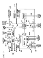
- FIG. 7 depicts, in simplified block diagram form, a detailed view of multiplex system controller 105 (FIG. 2).
- Pack counter 615 determines which pack is being multiplexed and supplies as an output its number i, which is simply ⁇ /T rounded up to the next integer. Whenever i changes in value, indicating a new pack, pack counter 615 also supplies as an output on line 513 an ENCODER PACK signal, which is sent to all of encoder rate controllers 103.
- Packet stop times and packet sizes are supplied from each of encoder rate controllers 103 to multiplexer system controller 105 and are received via lines 507 and 509, respectively. As soon as a packet stop time that is within the pack duration [(i-1)T,iT] arrives on one of lines 507, that packet and its associated stream is selected for multiplexing. An identification of the associated stream is then supplied by packet select 612 as an input to switch controller 613, which also reads the corresponding packet size that has been received as an input on one of lines 509.
- the stream identification and packet size are then supplied to mux switch 108 via link 107, thus enabling mux switch 108 to position itself correctly and pass the correct number of bits from the corresponding one of encoder buffers 106 to multiplex buffer 109.
- packet select 612 transmits a NEXT PKT signal to the above identified one of encoder rate controllers 103 via one of lines 508. This causes parameters for a new packet to be supplied from the identified one of encoder rate controllers 103.
- Packet start times are supplied from each of encoder rate controllers 103 via lines 506.
- the minimum value of the received packet start times ⁇ min is found by find minimum circuit 619 and that minimum value is supplied to compute 'tmax module 616.
- each of encoder rate controllers 103 transmit their RESERVATION REQUESTS to multiplex system controller 105.
- the RESERVATION REQUESTS are received as inputs via lines 504 by compute ⁇ max module 616.
- Compute ⁇ max module 616 adds the values of the bit-rates requested in each reservation requests, expressed in bits, and then divides the total by channel bit-rate R m to convert the total bit-rate request into a time value 'tres.
- ' t max is then computed by
- An indication of the fullness of multiplex buffer 109 is received via line 114 (FIG. 2) and is divided by channel bit-rate R m , by divider 620, to convert the fullness indication to an equivalent time value ⁇ buf .'tbuf is thus the time that will be required to transmit the bits stored in multiplex buffer 109. ⁇ buf is then supplied to generate decoder pack signal module 614 and compute available capacity module 617.
- the values of indications of the fullness of encoder buffers 106, expressed in bits, are supplied to multiplex system controller 105 via lines 512 and are totalled by adder 620, which supplies theirsum SUM encbuf to compute available capacity module 617.
- the available capacity, expressed in bits, is determined by in compute available capacity module 617.
- one of encoder buffers 106 may be made larger than described here in order to add some desired delay. For example, an audio access unit would normally have to be delayed considerably prior to its encoding so as to be matched up with its corresponding video access unit as described above. Under such circumstances, it may be more economical to delay the encoded compressed audio signal by simply providing it with a larger one of encoder buffers 106. A side effect of doing so is that the resulting encoder buffer fullness is much larger than it would be otherwise. Therefore, in such an embodiment, the values of indications of the fullness of encoder buffers 106 from lines 115 or 512 can be replaced by the corresponding packet size value from the corresponding one of encoder rate controllers 103 that are received as inputs via one of lines 509. In fact, replacing all of the values of indications of the fullness of encoder buffers 106 received from lines 512 with their corresponding packet sizes on line 509 will not affect performance of encoder system 100 very much.
- C avail is supplied to threshold detector 618, which checks to determine if available capacity is too low by determining if the available capacity is below a predetermined threshold that is set to some fraction, e.g, 5%, of maximum ip M R m . If it is, a REDUCE BIT-RATE signal is transmitted via line 606 to all of encoder rate controllers 103 to instruct them to lower their generated bit-rates.
- Generate decoder pack signal module 614 supplies a DECODER PACK signal via line 514 to all of encoder rate controllers 103 whenever Tbuf crosses a decoded pack boundary, as described above.
- the decoder pack boundary is the decoder version of the end of the pack duration. It is the latest time that any packet of the pack will be decoded by its respective decoder and therefore can be used by decoder buffer counter 521 in FIG. 6 to compute an upper bound on decoder buffer fullness.
- the decoded pack number j is simply ⁇ buf /T rounded up to the next integer. Whenever j changes in value, indicating a new decoded pack has been taken from the decoder buffers, a DECODER PACK signal is generated.
- multiplex buffer 109 is large, e.g., able to hold L packets from all streams, relative to each of encoder buffers 106 which typically hold only one pack from one stream.
- mux switch 108 output will have limited bandwidth and cannot empty encoder buffers 106 in less than the pack duration, which as was assumed heretofore.
- encoder buffers 106 will hold not only packets that have not been multiplexed, but also packets that have been multiplexed and are awaiting transmission.
- multiplex requests from multiplex system controller 105 to multiplex switch 108 will have to be queued by multiplex switch 108.
- indications of the fullness of multiplex buffer 109 will have to be replaced by a sum of the queued packet sizes.
- encoder buffers 106 in such an embodiment hold more than unmultiplexed packets, the encoder buffer fullnesses received via lines 512 (as shown in FIG. 7) should be replaced by the same packet sizes as are received via lines 509.
- video signals have been used herein in an exemplary fashion and that the scope of then invention does not require that video signals actually be at least one of the signals encoded and transmitted over the variable bit-rate channel. Any signals capable of being divided into units and encoded may be employed within the scope of the invention.
Landscapes
- Engineering & Computer Science (AREA)
- Signal Processing (AREA)
- Multimedia (AREA)
- Computer Networks & Wireless Communication (AREA)
- Databases & Information Systems (AREA)
- Compression Or Coding Systems Of Tv Signals (AREA)
- Communication Control (AREA)
- Transmission Systems Not Characterized By The Medium Used For Transmission (AREA)
Applications Claiming Priority (2)
| Application Number | Priority Date | Filing Date | Title |
|---|---|---|---|
| US704551 | 1991-05-23 | ||
| US07/704,551 US5159447A (en) | 1991-05-23 | 1991-05-23 | Buffer control for variable bit-rate channel |
Publications (3)
| Publication Number | Publication Date |
|---|---|
| EP0515101A2 true EP0515101A2 (de) | 1992-11-25 |
| EP0515101A3 EP0515101A3 (en) | 1993-06-30 |
| EP0515101B1 EP0515101B1 (de) | 1997-07-23 |
Family
ID=24829971
Family Applications (1)
| Application Number | Title | Priority Date | Filing Date |
|---|---|---|---|
| EP92304377A Expired - Lifetime EP0515101B1 (de) | 1991-05-23 | 1992-05-14 | Puffersteuerung für einen Kanal mit variabler Bitrate |
Country Status (5)
| Country | Link |
|---|---|
| US (1) | US5159447A (de) |
| EP (1) | EP0515101B1 (de) |
| JP (1) | JP2648418B2 (de) |
| KR (1) | KR950005618B1 (de) |
| DE (1) | DE69221028T2 (de) |
Cited By (46)
| Publication number | Priority date | Publication date | Assignee | Title |
|---|---|---|---|---|
| EP0517273A3 (de) * | 1991-06-07 | 1994-01-05 | Alcatel Espacio Sa | |
| GB2274041A (en) * | 1990-01-19 | 1994-07-06 | British Broadcasting Corp | Buffer Resynchronisation in a variable transmission rate coder |
| WO1995002301A3 (en) * | 1993-07-06 | 1995-03-09 | Zenith Electronics Corp | System for multiplexed transmission of compressed video and auxiliary data |
| EP0618695A3 (de) * | 1993-03-31 | 1995-05-03 | Sony Corp | Multiplex codierter Datensignale. |
| EP0643537A3 (de) * | 1993-09-10 | 1995-05-24 | Philips Electronics Nv | Anlage um eine Mehrzahl Fernsehsignale mittels eines übertragungskanals zu übertragen. |
| EP0675656A3 (de) * | 1994-03-31 | 1996-02-07 | Victor Company Of Japan | Bewegtbildkodierungsvorrichtung. |
| WO1996008115A1 (en) * | 1994-09-07 | 1996-03-14 | Philips Electronics N.V. | Mpeg information signal conversion system |
| EP0665693A3 (de) * | 1993-12-28 | 1996-03-27 | Matsushita Electric Industrial Co Ltd | Dynamisches Bitratensteuerungsverfahren für Video mit sehr niedriger Datenrate und entsprechende Audiokodierung. |
| EP0663774A3 (de) * | 1994-01-18 | 1996-03-27 | Daewoo Electronics Co Ltd | Einrichtung zur adaptiven Demultiplexierung eines Bitstroms in einem Dekodierungssystem. |
| EP0654947A4 (de) * | 1993-06-08 | 1996-04-03 | Sony Corp | Kodierer und verfahren zur kodierung. |
| FR2740639A1 (fr) * | 1995-10-30 | 1997-04-30 | Nec Corp | Systeme de decodage pour donnees cinematographiques |
| GB2307151A (en) * | 1995-11-10 | 1997-05-14 | British Broadcasting Corp | Digital coding of video signals |
| WO1997019561A1 (en) * | 1995-11-21 | 1997-05-29 | Imedia Corporation | Method and apparatus for multiplexing video programs |
| WO1997035435A1 (en) * | 1996-03-19 | 1997-09-25 | Sony Corporation | Data multiplexing apparatus and method thereof |
| FR2748623A1 (fr) * | 1996-05-09 | 1997-11-14 | Thomson Multimedia Sa | Encodeur a debit variable |
| EP0676899A3 (de) * | 1994-04-06 | 1997-11-19 | AT&T Corp. | Audiovisuelles Kommunikationssystem mit integrierter, wahrnehmungsabhängiger Sprach- und Videokodierung |
| EP0708566A3 (de) * | 1994-10-21 | 1997-12-17 | AT&T Corp. | Verfahren zur Steuerung eines Bildkodiererpuffers |
| WO1998009442A1 (en) * | 1996-08-30 | 1998-03-05 | Philips Electronics N.V. | Video transmission system |
| EP0705042A3 (de) * | 1994-09-29 | 1998-12-23 | CSELT Centro Studi e Laboratori Telecomunicazioni S.p.A. | Verfahren zur Zusammenfügung von audiovisuellen Datenströmen, die entsprechend des MPEG1-Standards codiert sind |
| EP0711080A3 (de) * | 1994-11-01 | 1999-04-07 | AT&T Corp. | Bildkomposition mit kodierten Bilddatenströmen für multimediale Kommunikationssysteme |
| EP0711077A3 (de) * | 1994-11-01 | 1999-04-14 | AT&T Corp. | Anpassung der Videoübertragungsgeschwindigkeit für Multimedia-Übertragungssysteme |
| GB2331678A (en) * | 1997-11-25 | 1999-05-26 | Daewoo Electronics Co Ltd | Controlling data flow in a synchronous data compression system |
| EP0778708A3 (de) * | 1995-12-04 | 1999-07-14 | Tektronix, Inc. | Bitratensteuerung für Videodaten |
| EP0550843B1 (de) * | 1991-12-24 | 1999-08-11 | General Instrument Corporation | Statistischer Multiplexer für ein Multikanal-Bildkomprimierungssystem und Demultiplexer |
| US5956088A (en) * | 1995-11-21 | 1999-09-21 | Imedia Corporation | Method and apparatus for modifying encoded digital video for improved channel utilization |
| WO1999055092A3 (en) * | 1998-04-17 | 1999-12-02 | Tiernan Communications Inc | Apparatus and method for dynamic multiplexing |
| GB2347326A (en) * | 1999-02-26 | 2000-08-30 | Mitel Inc | Text-to-speech converter |
| WO2000072599A1 (en) * | 1999-05-21 | 2000-11-30 | Edge Networks Corporation | Media server with multi-dimensional scalable data compression |
| EP0695099B1 (de) * | 1994-07-29 | 2001-11-07 | Pioneer Video Corporation | Aufnahmescheibe und Anlage zur Wiedergabe aufgenommener Information |
| EP0772927A4 (de) * | 1994-05-20 | 2002-08-28 | Compression Labs Inc | Verfahren zur dynamischen zuweisung von kommunikationskanal-bandbreite zwischen konkurrierenden anwendungen |
| WO2003098935A3 (en) * | 2002-05-22 | 2004-02-12 | Koninkl Philips Electronics Nv | Transmission method using a virtual reception buffer to absorb fluctuation of the channel transmission rate |
| EP0932308A3 (de) * | 1998-01-26 | 2006-02-08 | Sony Corporation | Verfahren und Vorrichtung zum Multiplexen, Übertragen und Aufzeichnen von Digitalsignalen sowie Aufzeichnungsträger |
| EP1624693A1 (de) * | 2004-07-01 | 2006-02-08 | Nextream France | Vorrichtung und Verfahren zum multiplexen von Daten eines Kodierers über ein Kommunikationsnetzwerk |
| WO2006082485A1 (en) * | 2005-02-03 | 2006-08-10 | Nokia Corporation | Signaling buffer parameters indicative of receiver buffer architecture |
| EP0660613A4 (de) * | 1993-07-12 | 2006-11-22 | Sony Corp | Bildsignalwiedergabeverfahren und -vorrichtung |
| EP1746844A2 (de) | 2001-09-19 | 2007-01-24 | Microsoft Corporation | Generalisierter Bilddecodierer und -videodecodierer |
| EP1590741A4 (de) * | 2003-01-10 | 2010-06-16 | Realnetworks Inc | Stochastisches adaptives streaming von inhalt |
| EP1365560A4 (de) * | 2001-09-14 | 2010-06-23 | Panasonic Corp | Transportstromdecodierer für mehrere formate |
| EP1769399A4 (de) * | 2004-06-07 | 2013-04-03 | Sling Media Inc | Persönliches media-ausstrahlungssystem |
| US8799969B2 (en) | 2004-06-07 | 2014-08-05 | Sling Media, Inc. | Capturing and sharing media content |
| US8904455B2 (en) | 2004-06-07 | 2014-12-02 | Sling Media Inc. | Personal video recorder functionality for placeshifting systems |
| EP2457167A4 (de) * | 2009-07-24 | 2015-09-02 | Netflix Inc | Adaptives streaming zur verteilung digitaler inhalte |
| US9131253B2 (en) | 2004-06-07 | 2015-09-08 | Sling Media, Inc. | Selection and presentation of context-relevant supplemental content and advertising |
| US9521354B2 (en) | 2009-07-24 | 2016-12-13 | Netflix, Inc. | Adaptive streaming for digital content distribution |
| US9584757B2 (en) | 1999-05-26 | 2017-02-28 | Sling Media, Inc. | Apparatus and method for effectively implementing a wireless television system |
| US9998802B2 (en) | 2004-06-07 | 2018-06-12 | Sling Media LLC | Systems and methods for creating variable length clips from a media stream |
Families Citing this family (128)
| Publication number | Priority date | Publication date | Assignee | Title |
|---|---|---|---|---|
| GB9022326D0 (en) * | 1990-10-15 | 1990-11-28 | British Telecomm | Signal coding |
| DE69125370T2 (de) * | 1991-08-28 | 1997-08-14 | Alcatel Bell Nv | Kodieranordnung |
| US6041144A (en) * | 1991-09-17 | 2000-03-21 | Canon Kabushiki Kaisha | Image processing apparatus |
| US6167539A (en) * | 1991-11-14 | 2000-12-26 | Canon Kabushiki Kaisha | Transmitting apparatus with code formation based on detected transmission channel data |
| JP3241778B2 (ja) * | 1991-12-24 | 2001-12-25 | ソニー株式会社 | 符号化装置 |
| WO1993015571A1 (en) * | 1992-01-29 | 1993-08-05 | Bell Communications Research, Inc. | Smoothing delay-sensitive traffic offered to atm networks |
| US5412782A (en) | 1992-07-02 | 1995-05-02 | 3Com Corporation | Programmed I/O ethernet adapter with early interrupts for accelerating data transfer |
| US5287182A (en) * | 1992-07-02 | 1994-02-15 | At&T Bell Laboratories | Timing recovery for variable bit-rate video on asynchronous transfer mode (ATM) networks |
| JP2871316B2 (ja) * | 1992-07-10 | 1999-03-17 | 日本ビクター株式会社 | 動画像符号化装置 |
| EP0595268B1 (de) * | 1992-10-28 | 2001-03-21 | Victor Company Of Japan, Limited | Kodiervorrichtung und -verfahren mit variablen Übertragungsraten |
| US5317604A (en) * | 1992-12-30 | 1994-05-31 | Gte Government Systems Corporation | Isochronous interface method |
| US5317603A (en) * | 1992-12-30 | 1994-05-31 | Gte Government Systems Corporation | Isochronous interface apparatus |
| US5426463A (en) * | 1993-02-22 | 1995-06-20 | Rca Thomson Licensing Corporation | Apparatus for controlling quantizing in a video signal compressor |
| EP0614317A3 (de) * | 1993-03-05 | 1995-01-25 | Sony Corp | Dekodierung von Videosignalen. |
| US5410355A (en) * | 1993-04-02 | 1995-04-25 | Rca Thomson Licensing Corporation | Video signal processor including input codeword buffer for providing stored codewords to codeword priority analysis circuit |
| US5463422A (en) * | 1993-10-13 | 1995-10-31 | Auravision Corporation | Data processing technique for limiting the bandwidth of data to be stored in a buffer |
| US5452235A (en) * | 1993-11-01 | 1995-09-19 | Intel Corp. | Planar/packed video data FIFO memory device |
| JP2658832B2 (ja) * | 1993-11-12 | 1997-09-30 | 日本電気株式会社 | 動画像復号制御装置 |
| US5847765A (en) * | 1993-11-12 | 1998-12-08 | Nec Corporation | Moving picture decoding control system |
| JP3535549B2 (ja) | 1993-12-22 | 2004-06-07 | 日本放送協会 | 画像信号符号化多重装置 |
| JP3535548B2 (ja) | 1993-12-22 | 2004-06-07 | 日本放送協会 | 多チャネル画像信号符号化多重装置 |
| US5592226A (en) * | 1994-01-26 | 1997-01-07 | Btg Usa Inc. | Method and apparatus for video data compression using temporally adaptive motion interpolation |
| CN1129263C (zh) * | 1994-02-17 | 2003-11-26 | 摩托罗拉公司 | 分组编码信号的方法和装置 |
| CA2140850C (en) * | 1994-02-24 | 1999-09-21 | Howard Paul Katseff | Networked system for display of multimedia presentations |
| US5563961A (en) * | 1994-03-03 | 1996-10-08 | Radius Inc. | Video data compression method and system which measures compressed data storage time to optimize compression rate |
| JP3167863B2 (ja) | 1994-07-08 | 2001-05-21 | 株式会社ディーディーアイ | 映像符号化器系の制御装置 |
| US5566208A (en) * | 1994-03-17 | 1996-10-15 | Philips Electronics North America Corp. | Encoder buffer having an effective size which varies automatically with the channel bit-rate |
| JPH07284096A (ja) * | 1994-04-06 | 1995-10-27 | Nec Corp | 多チャンネル画像伝送装置 |
| US5534937A (en) * | 1994-04-14 | 1996-07-09 | Motorola, Inc. | Minimum-delay jitter smoothing device and method for packet video communications |
| CA2146801C (en) * | 1994-05-27 | 1999-11-02 | Barin Geoffry Haskell | Timing recovery for variable bit-rate video on asynchronous transfer mode (atm) networks |
| US5734432A (en) * | 1994-07-15 | 1998-03-31 | Lucent Technologies, Inc. | Method of incorporating a variable rate auxiliary data stream with a variable rate primary data stream |
| US5761223A (en) * | 1994-07-21 | 1998-06-02 | Matsushita Electric Industrial Co., Ltd. | Error correcting device |
| JP2935334B2 (ja) * | 1994-07-28 | 1999-08-16 | 日本電気株式会社 | 符号量制御方法 |
| DE69536032D1 (de) * | 1994-10-21 | 2010-02-04 | At & T Corp | Verfahren zur Synchronisation von Pufferspeichern für Videosignale |
| JP3058028B2 (ja) * | 1994-10-31 | 2000-07-04 | 三菱電機株式会社 | 画像符号化データ再符号化装置 |
| US5754241A (en) * | 1994-11-18 | 1998-05-19 | Sanyo Electric Co., Ltd | Video decoder capable of controlling encoded video data |
| EP0753235B1 (de) * | 1994-12-28 | 2000-07-12 | Koninklijke Philips Electronics N.V. | Pufferverwaltung in kompressionssystemen mit variabler bitrate |
| US5543853A (en) * | 1995-01-19 | 1996-08-06 | At&T Corp. | Encoder/decoder buffer control for variable bit-rate channel |
| US5835711A (en) * | 1995-02-01 | 1998-11-10 | International Business Machines Corporation | Method and system for implementing multiple leaky bucket checkers using a hybrid synchronous/asynchronous update mechanism |
| US5619341A (en) * | 1995-02-23 | 1997-04-08 | Motorola, Inc. | Method and apparatus for preventing overflow and underflow of an encoder buffer in a video compression system |
| US5677969A (en) * | 1995-02-23 | 1997-10-14 | Motorola, Inc. | Method, rate controller, and system for preventing overflow and underflow of a decoder buffer in a video compression system |
| US5754866A (en) * | 1995-05-08 | 1998-05-19 | Nvidia Corporation | Delayed interrupts with a FIFO in an improved input/output architecture |
| US5734843A (en) * | 1995-06-07 | 1998-03-31 | Advanced Micro Devices Inc. | Reverse data channel as a bandwidth modulator |
| FR2736743B1 (fr) * | 1995-07-10 | 1997-09-12 | France Telecom | Procede de controle de debit de sortie d'un codeur de donnees numeriques representatives de sequences d'images |
| US6075768A (en) * | 1995-11-09 | 2000-06-13 | At&T Corporation | Fair bandwidth sharing for video traffic sources using distributed feedback control |
| US5859980A (en) * | 1996-02-08 | 1999-01-12 | Advanced Micro Devices, Inc. | Network interface having adaptive transmit start point for each packet to avoid transmit underflow |
| US5760836A (en) * | 1996-08-22 | 1998-06-02 | International Business Machines Corporation | FIFO feedback and control for digital video encoder |
| CA2267152A1 (en) * | 1996-10-08 | 1998-04-16 | Tiernan Communications, Inc. | Apparatus and method for multi-service transport multiplexing |
| EP0888009B1 (de) * | 1996-12-12 | 2006-02-22 | Sony Corporation | Vorrichtung und verfahren zur kodierung von bilddaten sowie verfahren zur bilddatenübertragung |
| US6243417B1 (en) * | 1996-12-12 | 2001-06-05 | Sony Corporation | Device and method for encoding image data, and image data transmission method |
| JPH10208393A (ja) * | 1997-01-27 | 1998-08-07 | Sony Corp | ディジタル信号符号化方法及び装置 |
| US6418122B1 (en) * | 1997-03-21 | 2002-07-09 | Scientific-Atlanta, Inc. | Method and apparatus for assuring sufficient bandwidth of a statistical multiplexer |
| US6052384A (en) | 1997-03-21 | 2000-04-18 | Scientific-Atlanta, Inc. | Using a receiver model to multiplex variable-rate bit streams having timing constraints |
| US6021449A (en) * | 1997-08-01 | 2000-02-01 | International Business Machines Corporation | Video FIFO overflow control method that blocks video encoder data when overflow is imminent and resumes flow when frames sizes have returned to nominal size |
| US6188703B1 (en) | 1997-08-01 | 2001-02-13 | International Business Machines Corp. | Multiplexer for multiple media streams |
| US6678243B2 (en) * | 1997-11-14 | 2004-01-13 | Ess Technology, Inc. | Variable codec frame length |
| US6366704B1 (en) | 1997-12-01 | 2002-04-02 | Sharp Laboratories Of America, Inc. | Method and apparatus for a delay-adaptive rate control scheme for the frame layer |
| US6556560B1 (en) | 1997-12-04 | 2003-04-29 | At&T Corp. | Low-latency audio interface for packet telephony |
| US6301258B1 (en) * | 1997-12-04 | 2001-10-09 | At&T Corp. | Low-latency buffering for packet telephony |
| US6192032B1 (en) | 1998-01-02 | 2001-02-20 | International Business Machines Corporation | Rate attenuation systems, methods and computer program products for reducing low priority video frame packets transmitted over a network |
| US6173069B1 (en) | 1998-01-09 | 2001-01-09 | Sharp Laboratories Of America, Inc. | Method for adapting quantization in video coding using face detection and visual eccentricity weighting |
| US6396956B1 (en) | 1998-03-31 | 2002-05-28 | Sharp Laboratories Of America, Inc. | Method and apparatus for selecting image data to skip when encoding digital video |
| US6169747B1 (en) * | 1998-07-08 | 2001-01-02 | Ess Technology, Inc. | Variable code frame length for multistream applications |
| JP3520851B2 (ja) * | 1998-11-12 | 2004-04-19 | ソニー株式会社 | データ多重化装置およびデータ多重化方法、並びにデータ伝送装置 |
| US6272566B1 (en) * | 1998-11-18 | 2001-08-07 | International Business Machines Corporation | System for maintaining proper buffering within video play list |
| US6665728B1 (en) * | 1998-12-30 | 2003-12-16 | Intel Corporation | Establishing optimal latency in streaming data applications that use data packets |
| IL129345A (en) * | 1999-04-06 | 2004-05-12 | Broadcom Corp | Video encoding and video/audio/data multiplexing device |
| US8270479B2 (en) * | 1999-04-06 | 2012-09-18 | Broadcom Corporation | System and method for video and audio encoding on a single chip |
| US20040161032A1 (en) * | 1999-04-06 | 2004-08-19 | Amir Morad | System and method for video and audio encoding on a single chip |
| CA2271539A1 (en) * | 1999-05-12 | 2000-11-12 | Pmc-Sierra Inc. | Interface between a link layer device and one or more physical layer devices |
| US8266657B2 (en) | 2001-03-15 | 2012-09-11 | Sling Media Inc. | Method for effectively implementing a multi-room television system |
| US6535251B1 (en) | 1999-10-26 | 2003-03-18 | Sharplabs Of America, Inc. | Video encoder and method for adjusting quantization step in real time |
| US7187947B1 (en) | 2000-03-28 | 2007-03-06 | Affinity Labs, Llc | System and method for communicating selected information to an electronic device |
| KR100341063B1 (ko) | 2000-06-28 | 2002-06-20 | 송문섭 | 실시간 영상 통신을 위한 율제어 장치 및 그 방법 |
| KR100628619B1 (ko) * | 2000-07-10 | 2006-09-26 | 마쯔시다덴기산교 가부시키가이샤 | 복수의 디코드 장치 및 방법 |
| US7418007B1 (en) * | 2000-09-20 | 2008-08-26 | General Instrument Corporation | Method and apparatus for determining a transmission bit rate in a statistical multiplexer |
| CN100420250C (zh) * | 2000-11-29 | 2008-09-17 | 英国电讯有限公司 | 通信设备操作方法、数据呈现方法和设备 |
| US20030223735A1 (en) * | 2001-02-28 | 2003-12-04 | Boyle William B. | System and a method for receiving and storing a transport stream for deferred presentation of a program to a user |
| US6907481B2 (en) * | 2001-03-06 | 2005-06-14 | Ati Technologies, Inc. | System for bit-rate controlled digital stream playback and method thereof |
| US8121296B2 (en) | 2001-03-28 | 2012-02-21 | Qualcomm Incorporated | Method and apparatus for security in a data processing system |
| US9100457B2 (en) | 2001-03-28 | 2015-08-04 | Qualcomm Incorporated | Method and apparatus for transmission framing in a wireless communication system |
| US8077679B2 (en) | 2001-03-28 | 2011-12-13 | Qualcomm Incorporated | Method and apparatus for providing protocol options in a wireless communication system |
| US20040097720A1 (en) * | 2001-04-02 | 2004-05-20 | Bott Richard R. | Use of glycodendrimer reagents for inhibiting adhesion by microorganisms |
| US7460629B2 (en) * | 2001-06-29 | 2008-12-02 | Agere Systems Inc. | Method and apparatus for frame-based buffer control in a communication system |
| US7412004B2 (en) * | 2001-06-29 | 2008-08-12 | Agere Systems Inc. | Method and apparatus for controlling buffer overflow in a communication system |
| US7075990B2 (en) * | 2001-08-28 | 2006-07-11 | Sbc Properties, L.P. | Method and system to improve the transport of compressed video data in real time |
| US6970512B2 (en) * | 2001-08-28 | 2005-11-29 | Sbc Technology Resources, Inc. | Method and system to improve the transport of compressed video data |
| US7352868B2 (en) | 2001-10-09 | 2008-04-01 | Philip Hawkes | Method and apparatus for security in a data processing system |
| US7649829B2 (en) | 2001-10-12 | 2010-01-19 | Qualcomm Incorporated | Method and system for reduction of decoding complexity in a communication system |
| KR100954253B1 (ko) * | 2001-11-30 | 2010-04-23 | 브리티쉬 텔리커뮤니케이션즈 파블릭 리미티드 캄퍼니 | 데이터 전송 시스템, 동작 방법 및 디지털 미디어 캐리어 |
| US20050169245A1 (en) * | 2002-03-04 | 2005-08-04 | Lars Hindersson | Arrangement and a method for handling an audio signal |
| EP1359722A1 (de) | 2002-03-27 | 2003-11-05 | BRITISH TELECOMMUNICATIONS public limited company | System und Verfahren zur Übertragung von Datenströmen |
| DE60335178D1 (de) * | 2002-03-27 | 2011-01-13 | British Telecomm | Videokodierung und -übertragung |
| EP1488644B1 (de) * | 2002-03-27 | 2007-05-30 | British Telecommunications Public Limited Company | Datenstruktur für ein datenübertragungssystem |
| US8798167B2 (en) * | 2002-11-29 | 2014-08-05 | Sony Corporation | Encoder and its method |
| US7599655B2 (en) | 2003-01-02 | 2009-10-06 | Qualcomm Incorporated | Method and apparatus for broadcast services in a communication system |
| US20040143850A1 (en) * | 2003-01-16 | 2004-07-22 | Pierre Costa | Video Content distribution architecture |
| US20040143849A1 (en) * | 2003-01-16 | 2004-07-22 | Pierre Costa | Method and system to create a deterministic traffic profile for isochronous data networks |
| GB0306296D0 (en) * | 2003-03-19 | 2003-04-23 | British Telecomm | Data transmission |
| US7266147B2 (en) * | 2003-03-31 | 2007-09-04 | Sharp Laboratories Of America, Inc. | Hypothetical reference decoder |
| US20060072837A1 (en) * | 2003-04-17 | 2006-04-06 | Ralston John D | Mobile imaging application, device architecture, and service platform architecture |
| US7274740B2 (en) | 2003-06-25 | 2007-09-25 | Sharp Laboratories Of America, Inc. | Wireless video transmission system |
| US7391769B2 (en) * | 2003-06-27 | 2008-06-24 | Lucent Technologies Inc. | Packet aggregation for real time services on packet data networks |
| US8098818B2 (en) | 2003-07-07 | 2012-01-17 | Qualcomm Incorporated | Secure registration for a multicast-broadcast-multimedia system (MBMS) |
| US8718279B2 (en) | 2003-07-08 | 2014-05-06 | Qualcomm Incorporated | Apparatus and method for a secure broadcast system |
| US20050036548A1 (en) * | 2003-08-12 | 2005-02-17 | Yong He | Method and apparatus for selection of bit budget adjustment in dual pass encoding |
| US8724803B2 (en) | 2003-09-02 | 2014-05-13 | Qualcomm Incorporated | Method and apparatus for providing authenticated challenges for broadcast-multicast communications in a communication system |
| US9325998B2 (en) * | 2003-09-30 | 2016-04-26 | Sharp Laboratories Of America, Inc. | Wireless video transmission system |
| US7016409B2 (en) * | 2003-11-12 | 2006-03-21 | Sony Corporation | Apparatus and method for use in providing dynamic bit rate encoding |
| US8018850B2 (en) * | 2004-02-23 | 2011-09-13 | Sharp Laboratories Of America, Inc. | Wireless video transmission system |
| AU2005295132A1 (en) * | 2004-10-12 | 2006-04-20 | Droplet Technology, Inc. | Mobile imaging application, device architecture, and service platform architecture |
| US7797723B2 (en) * | 2004-10-30 | 2010-09-14 | Sharp Laboratories Of America, Inc. | Packet scheduling for video transmission with sender queue control |
| US8356327B2 (en) * | 2004-10-30 | 2013-01-15 | Sharp Laboratories Of America, Inc. | Wireless video transmission system |
| US7784076B2 (en) * | 2004-10-30 | 2010-08-24 | Sharp Laboratories Of America, Inc. | Sender-side bandwidth estimation for video transmission with receiver packet buffer |
| US8218657B2 (en) * | 2005-09-02 | 2012-07-10 | Netgear, Inc. | System and method for automatic adjustment of streaming video bit rate |
| US20070067480A1 (en) * | 2005-09-19 | 2007-03-22 | Sharp Laboratories Of America, Inc. | Adaptive media playout by server media processing for robust streaming |
| US9544602B2 (en) * | 2005-12-30 | 2017-01-10 | Sharp Laboratories Of America, Inc. | Wireless video transmission system |
| US7652994B2 (en) * | 2006-03-31 | 2010-01-26 | Sharp Laboratories Of America, Inc. | Accelerated media coding for robust low-delay video streaming over time-varying and bandwidth limited channels |
| US8861597B2 (en) * | 2006-09-18 | 2014-10-14 | Sharp Laboratories Of America, Inc. | Distributed channel time allocation for video streaming over wireless networks |
| US7885189B2 (en) * | 2006-09-20 | 2011-02-08 | Rgb Networks, Inc. | Methods and apparatus for rate estimation and predictive rate control |
| US7652993B2 (en) * | 2006-11-03 | 2010-01-26 | Sharp Laboratories Of America, Inc. | Multi-stream pro-active rate adaptation for robust video transmission |
| US7843824B2 (en) * | 2007-01-08 | 2010-11-30 | General Instrument Corporation | Method and apparatus for statistically multiplexing services |
| US20100333149A1 (en) * | 2009-06-24 | 2010-12-30 | Rgb Networks, Inc. | Delivery of pre-statistically multiplexed streams in a vod system |
| US9167256B2 (en) * | 2010-08-31 | 2015-10-20 | Arris Technology, Inc. | Method and apparatus for encoding |
| FR3009153B1 (fr) * | 2013-07-24 | 2015-08-21 | France Brevets | Systeme et procede pour la transmission de donnees et de flux contenant des donnees video dvideo dans un canal a debit donne |
| CN105849800B (zh) | 2013-12-02 | 2020-04-10 | 杜比国际公司 | 位速率估值确定方法、位速率估算器、多路复用设备、位流提供方法和编码系统 |
| KR102287274B1 (ko) * | 2019-12-05 | 2021-08-06 | 울산과학기술원 | 비디오 인코딩 장치 및 방법 |
| CN116074539B (zh) * | 2022-07-27 | 2024-10-29 | 杭州海康威视数字技术股份有限公司 | 一种图像编解码方法及装置 |
Family Cites Families (11)
| Publication number | Priority date | Publication date | Assignee | Title |
|---|---|---|---|---|
| JPS59183548A (ja) * | 1983-04-01 | 1984-10-18 | Fujitsu Ltd | バツフアメモリを用いたデ−タ伝送方式におけるクロツク周波数同期方式 |
| JPS61107818A (ja) * | 1984-10-30 | 1986-05-26 | Nec Corp | エントロピ−符号化方式とその装置 |
| EP0241745B1 (de) * | 1986-04-04 | 1991-11-06 | Siemens Aktiengesellschaft | Verfahren zur Datenreduktion digitaler Bildsignale durch Vektorquantisierung von durch orthonormale Transformation mittels einer symmetrischen fastzyklischen Hadamard-Matrix gewonnenen Koeffizienten |
| US4706260A (en) * | 1986-11-07 | 1987-11-10 | Rca Corporation | DPCM system with rate-of-fill control of buffer occupancy |
| US4833535A (en) * | 1987-02-04 | 1989-05-23 | Kabushiki Kaisha Toshiba | Image transmission apparatus |
| EP0624985B1 (de) * | 1987-04-28 | 2001-03-14 | Mitsubishi Denki Kabushiki Kaisha | System zur Bildcodierung und -decodierung |
| FR2625060B1 (fr) * | 1987-12-16 | 1990-10-05 | Guichard Jacques | Procede et dispositifs de codage et de decodage pour la transmission d'images a travers un reseau a debit variable |
| US5073821A (en) * | 1989-01-30 | 1991-12-17 | Matsushita Electric Industrial Co., Ltd. | Orthogonal transform coding apparatus for reducing the amount of coded signals to be processed and transmitted |
| JPH0832034B2 (ja) * | 1989-08-03 | 1996-03-27 | 富士通株式会社 | 伝送レート可変式画像符号化装置 |
| GB9001295D0 (en) * | 1990-01-19 | 1990-03-21 | British Broadcasting Corp | Buffer resynchronisation |
| US5038209A (en) * | 1990-09-27 | 1991-08-06 | At&T Bell Laboratories | Adaptive buffer/quantizer control for transform video coders |
-
1991
- 1991-05-23 US US07/704,551 patent/US5159447A/en not_active Expired - Lifetime
-
1992
- 1992-05-11 JP JP4143646A patent/JP2648418B2/ja not_active Expired - Lifetime
- 1992-05-14 DE DE69221028T patent/DE69221028T2/de not_active Expired - Lifetime
- 1992-05-14 EP EP92304377A patent/EP0515101B1/de not_active Expired - Lifetime
- 1992-05-23 KR KR1019920008813A patent/KR950005618B1/ko not_active Expired - Lifetime
Cited By (80)
| Publication number | Priority date | Publication date | Assignee | Title |
|---|---|---|---|---|
| GB2274041A (en) * | 1990-01-19 | 1994-07-06 | British Broadcasting Corp | Buffer Resynchronisation in a variable transmission rate coder |
| GB2274041B (en) * | 1990-01-19 | 1994-09-14 | British Broadcasting Corp | Buffer regulation |
| EP0517273A3 (de) * | 1991-06-07 | 1994-01-05 | Alcatel Espacio Sa | |
| EP0550843B1 (de) * | 1991-12-24 | 1999-08-11 | General Instrument Corporation | Statistischer Multiplexer für ein Multikanal-Bildkomprimierungssystem und Demultiplexer |
| US5511054A (en) * | 1993-03-31 | 1996-04-23 | Sony Corporation | Apparatus and method for multiplexing encoded data signals and recording medium having multiplexed signals recorded thereon |
| EP0618695A3 (de) * | 1993-03-31 | 1995-05-03 | Sony Corp | Multiplex codierter Datensignale. |
| EP0654947A4 (de) * | 1993-06-08 | 1996-04-03 | Sony Corp | Kodierer und verfahren zur kodierung. |
| US5627581A (en) * | 1993-06-08 | 1997-05-06 | Sony Corporation | Encoding apparatus and encoding method |
| CN1052366C (zh) * | 1993-07-06 | 2000-05-10 | 齐尼思电子公司 | 形成数据传输帧的方法及进行该方法的系统 |
| WO1995002301A3 (en) * | 1993-07-06 | 1995-03-09 | Zenith Electronics Corp | System for multiplexed transmission of compressed video and auxiliary data |
| EP2278805A2 (de) * | 1993-07-12 | 2011-01-26 | Sony Corporation | Bildsignalwiedergabeverfahren und -Vorrichtung |
| EP0660613A4 (de) * | 1993-07-12 | 2006-11-22 | Sony Corp | Bildsignalwiedergabeverfahren und -vorrichtung |
| EP0643537A3 (de) * | 1993-09-10 | 1995-05-24 | Philips Electronics Nv | Anlage um eine Mehrzahl Fernsehsignale mittels eines übertragungskanals zu übertragen. |
| BE1007490A3 (nl) * | 1993-09-10 | 1995-07-11 | Philips Electronics Nv | Inrichting voor het overdragen van een pluraliteit van televisie signalen over een transmissie kanaal. |
| AU687848B2 (en) * | 1993-09-10 | 1998-03-05 | Koninklijke Philips Electronics N.V. | Device for transmitting a plurality of television signals through a transmission |
| EP0665693A3 (de) * | 1993-12-28 | 1996-03-27 | Matsushita Electric Industrial Co Ltd | Dynamisches Bitratensteuerungsverfahren für Video mit sehr niedriger Datenrate und entsprechende Audiokodierung. |
| US5617145A (en) * | 1993-12-28 | 1997-04-01 | Matsushita Electric Industrial Co., Ltd. | Adaptive bit allocation for video and audio coding |
| EP0663774A3 (de) * | 1994-01-18 | 1996-03-27 | Daewoo Electronics Co Ltd | Einrichtung zur adaptiven Demultiplexierung eines Bitstroms in einem Dekodierungssystem. |
| EP0675656A3 (de) * | 1994-03-31 | 1996-02-07 | Victor Company Of Japan | Bewegtbildkodierungsvorrichtung. |
| US6094224A (en) * | 1994-03-31 | 2000-07-25 | Victor Company Of Japan, Ltd. | Moving image coding device |
| EP0676899A3 (de) * | 1994-04-06 | 1997-11-19 | AT&T Corp. | Audiovisuelles Kommunikationssystem mit integrierter, wahrnehmungsabhängiger Sprach- und Videokodierung |
| EP1542383A1 (de) * | 1994-05-20 | 2005-06-15 | General Instrument Corporation | Verfahren zur dynamischen Zuweisung von Kommunikationskanal-bandbreite zwischen konkurrierenden Anwendungen |
| EP0772927A4 (de) * | 1994-05-20 | 2002-08-28 | Compression Labs Inc | Verfahren zur dynamischen zuweisung von kommunikationskanal-bandbreite zwischen konkurrierenden anwendungen |
| EP0695099B1 (de) * | 1994-07-29 | 2001-11-07 | Pioneer Video Corporation | Aufnahmescheibe und Anlage zur Wiedergabe aufgenommener Information |
| WO1996008115A1 (en) * | 1994-09-07 | 1996-03-14 | Philips Electronics N.V. | Mpeg information signal conversion system |
| EP0921690A3 (de) * | 1994-09-07 | 1999-07-14 | Koninklijke Philips Electronics N.V. | Umwandlungssystem für MPEG-Informationssignale |
| EP0705042A3 (de) * | 1994-09-29 | 1998-12-23 | CSELT Centro Studi e Laboratori Telecomunicazioni S.p.A. | Verfahren zur Zusammenfügung von audiovisuellen Datenströmen, die entsprechend des MPEG1-Standards codiert sind |
| EP0708566A3 (de) * | 1994-10-21 | 1997-12-17 | AT&T Corp. | Verfahren zur Steuerung eines Bildkodiererpuffers |
| EP0711080A3 (de) * | 1994-11-01 | 1999-04-07 | AT&T Corp. | Bildkomposition mit kodierten Bilddatenströmen für multimediale Kommunikationssysteme |
| EP0711077A3 (de) * | 1994-11-01 | 1999-04-14 | AT&T Corp. | Anpassung der Videoübertragungsgeschwindigkeit für Multimedia-Übertragungssysteme |
| FR2740639A1 (fr) * | 1995-10-30 | 1997-04-30 | Nec Corp | Systeme de decodage pour donnees cinematographiques |
| GB2307151A (en) * | 1995-11-10 | 1997-05-14 | British Broadcasting Corp | Digital coding of video signals |
| WO1997017809A1 (en) * | 1995-11-10 | 1997-05-15 | British Broadcasting Corporation | Digital coding |
| WO1997019561A1 (en) * | 1995-11-21 | 1997-05-29 | Imedia Corporation | Method and apparatus for multiplexing video programs |
| US5862140A (en) * | 1995-11-21 | 1999-01-19 | Imedia Corporation | Method and apparatus for multiplexing video programs for improved channel utilization |
| US5956088A (en) * | 1995-11-21 | 1999-09-21 | Imedia Corporation | Method and apparatus for modifying encoded digital video for improved channel utilization |
| EP0862835B1 (de) * | 1995-11-21 | 2009-09-30 | Imedia Corporation | Verfahren zur Veränderung kodierter digitaler Fernsehsignale zur besseren Kanalausnutzung mittels Reduzierung von kodierten B-Bilddaten |
| EP0778708A3 (de) * | 1995-12-04 | 1999-07-14 | Tektronix, Inc. | Bitratensteuerung für Videodaten |
| US6185229B1 (en) | 1996-03-19 | 2001-02-06 | Sony Corporation | Data multiplexing apparatus and method thereof |
| WO1997035435A1 (en) * | 1996-03-19 | 1997-09-25 | Sony Corporation | Data multiplexing apparatus and method thereof |
| US6212233B1 (en) | 1996-05-09 | 2001-04-03 | Thomson Licensing S.A. | Variable bit-rate encoder |
| FR2748623A1 (fr) * | 1996-05-09 | 1997-11-14 | Thomson Multimedia Sa | Encodeur a debit variable |
| WO1997043859A1 (fr) * | 1996-05-09 | 1997-11-20 | Thomson Multimedia | Encodeur a debit variable |
| WO1998009442A1 (en) * | 1996-08-30 | 1998-03-05 | Philips Electronics N.V. | Video transmission system |
| GB2331678A (en) * | 1997-11-25 | 1999-05-26 | Daewoo Electronics Co Ltd | Controlling data flow in a synchronous data compression system |
| EP0932308A3 (de) * | 1998-01-26 | 2006-02-08 | Sony Corporation | Verfahren und Vorrichtung zum Multiplexen, Übertragen und Aufzeichnen von Digitalsignalen sowie Aufzeichnungsträger |
| WO1999055092A3 (en) * | 1998-04-17 | 1999-12-02 | Tiernan Communications Inc | Apparatus and method for dynamic multiplexing |
| GB2347326A (en) * | 1999-02-26 | 2000-08-30 | Mitel Inc | Text-to-speech converter |
| US6546366B1 (en) | 1999-02-26 | 2003-04-08 | Mitel, Inc. | Text-to-speech converter |
| GB2347326B (en) * | 1999-02-26 | 2004-04-14 | Mitel Inc | Text-to-speech converter |
| WO2000072599A1 (en) * | 1999-05-21 | 2000-11-30 | Edge Networks Corporation | Media server with multi-dimensional scalable data compression |
| US9584757B2 (en) | 1999-05-26 | 2017-02-28 | Sling Media, Inc. | Apparatus and method for effectively implementing a wireless television system |
| EP1365560A4 (de) * | 2001-09-14 | 2010-06-23 | Panasonic Corp | Transportstromdecodierer für mehrere formate |
| EP1753248B1 (de) * | 2001-09-19 | 2016-03-30 | Microsoft Technology Licensing, LLC | Erzeugung und Übertragung von Einstellungen für generalisierten Referenzvideodekodierer |
| EP1746844A2 (de) | 2001-09-19 | 2007-01-24 | Microsoft Corporation | Generalisierter Bilddecodierer und -videodecodierer |
| EP1746844B1 (de) * | 2001-09-19 | 2016-03-30 | Microsoft Technology Licensing, LLC | Generalisierter Referenzvideodekodierer |
| EP1298938B1 (de) * | 2001-09-19 | 2017-02-15 | Microsoft Technology Licensing, LLC | Generalisierter Bilddecodierer und -videodecodierer |
| WO2003098935A3 (en) * | 2002-05-22 | 2004-02-12 | Koninkl Philips Electronics Nv | Transmission method using a virtual reception buffer to absorb fluctuation of the channel transmission rate |
| EP1590741A4 (de) * | 2003-01-10 | 2010-06-16 | Realnetworks Inc | Stochastisches adaptives streaming von inhalt |
| US10123067B2 (en) | 2004-06-07 | 2018-11-06 | Sling Media L.L.C. | Personal video recorder functionality for placeshifting systems |
| US9131253B2 (en) | 2004-06-07 | 2015-09-08 | Sling Media, Inc. | Selection and presentation of context-relevant supplemental content and advertising |
| US8621533B2 (en) | 2004-06-07 | 2013-12-31 | Sling Media, Inc. | Fast-start streaming and buffering of streaming content for personal media player |
| US8799969B2 (en) | 2004-06-07 | 2014-08-05 | Sling Media, Inc. | Capturing and sharing media content |
| US8904455B2 (en) | 2004-06-07 | 2014-12-02 | Sling Media Inc. | Personal video recorder functionality for placeshifting systems |
| US9106723B2 (en) | 2004-06-07 | 2015-08-11 | Sling Media, Inc. | Fast-start streaming and buffering of streaming content for personal media player |
| US10419809B2 (en) | 2004-06-07 | 2019-09-17 | Sling Media LLC | Selection and presentation of context-relevant supplemental content and advertising |
| EP1769399A4 (de) * | 2004-06-07 | 2013-04-03 | Sling Media Inc | Persönliches media-ausstrahlungssystem |
| US9998802B2 (en) | 2004-06-07 | 2018-06-12 | Sling Media LLC | Systems and methods for creating variable length clips from a media stream |
| US9716910B2 (en) | 2004-06-07 | 2017-07-25 | Sling Media, L.L.C. | Personal video recorder functionality for placeshifting systems |
| US9356984B2 (en) | 2004-06-07 | 2016-05-31 | Sling Media, Inc. | Capturing and sharing media content |
| US7561568B2 (en) | 2004-07-01 | 2009-07-14 | Thomson Licensing | Device and method for multiplexing associated with a coding device |
| AU2005202779B2 (en) * | 2004-07-01 | 2009-12-03 | Thomson Licensing S.A. | Device and method for multiplexing associated with a coding device |
| EP1624693A1 (de) * | 2004-07-01 | 2006-02-08 | Nextream France | Vorrichtung und Verfahren zum multiplexen von Daten eines Kodierers über ein Kommunikationsnetzwerk |
| WO2006082485A1 (en) * | 2005-02-03 | 2006-08-10 | Nokia Corporation | Signaling buffer parameters indicative of receiver buffer architecture |
| US8127040B2 (en) | 2005-02-03 | 2012-02-28 | Nokia Corporation | Signaling buffer parameters indicative of receiver buffer architecture |
| US9237300B2 (en) | 2005-06-07 | 2016-01-12 | Sling Media Inc. | Personal video recorder functionality for placeshifting systems |
| US9648385B2 (en) | 2009-07-24 | 2017-05-09 | Netflix, Inc. | Adaptive streaming for digital content distribution |
| US9521354B2 (en) | 2009-07-24 | 2016-12-13 | Netflix, Inc. | Adaptive streaming for digital content distribution |
| US9769505B2 (en) | 2009-07-24 | 2017-09-19 | Netflix, Inc. | Adaptive streaming for digital content distribution |
| EP2457167A4 (de) * | 2009-07-24 | 2015-09-02 | Netflix Inc | Adaptives streaming zur verteilung digitaler inhalte |
Also Published As
| Publication number | Publication date |
|---|---|
| KR950005618B1 (ko) | 1995-05-27 |
| JP2648418B2 (ja) | 1997-08-27 |
| US5159447A (en) | 1992-10-27 |
| JPH06253277A (ja) | 1994-09-09 |
| EP0515101A3 (en) | 1993-06-30 |
| EP0515101B1 (de) | 1997-07-23 |
| KR920022903A (ko) | 1992-12-19 |
| DE69221028D1 (de) | 1997-09-04 |
| DE69221028T2 (de) | 1997-11-13 |
Similar Documents
| Publication | Publication Date | Title |
|---|---|---|
| EP0515101B1 (de) | Puffersteuerung für einen Kanal mit variabler Bitrate | |
| EP1149498B1 (de) | Verfahren zür erfassung und verhinderung von bandbreiteüberlauf in einem statistischen multiplexer | |
| US6438139B1 (en) | Method and apparatus for using a receiver model to multiplex variable-rate bit streams having timing constraints | |
| US5543853A (en) | Encoder/decoder buffer control for variable bit-rate channel | |
| US6418122B1 (en) | Method and apparatus for assuring sufficient bandwidth of a statistical multiplexer | |
| EP0699368B1 (de) | Kodiererpuffer mit automatisch mit der kanalbitrate variierender effektiver grösse | |
| US5534937A (en) | Minimum-delay jitter smoothing device and method for packet video communications | |
| US6157653A (en) | Method and apparatus for adaptive smoothing delay for packet voice applications | |
| US6847656B1 (en) | Statistical remultiplexing with bandwidth allocation among different transcoding channels | |
| US5260978A (en) | Synchronous residual time stamp for timing recovery in a broadband network | |
| AU752737B2 (en) | Scheduling of bursty data streams over a fixed capacity channel | |
| EP0786885B1 (de) | Verfahren zur Paketverbindung | |
| Nguyen et al. | Buffer control for variable-bit-rate video over wireless ATM LAN |
Legal Events
| Date | Code | Title | Description |
|---|---|---|---|
| PUAI | Public reference made under article 153(3) epc to a published international application that has entered the european phase |
Free format text: ORIGINAL CODE: 0009012 |
|
| AK | Designated contracting states |
Kind code of ref document: A2 Designated state(s): DE FR GB NL |
|
| PUAL | Search report despatched |
Free format text: ORIGINAL CODE: 0009013 |
|
| AK | Designated contracting states |
Kind code of ref document: A3 Designated state(s): DE FR GB NL |
|
| 17P | Request for examination filed |
Effective date: 19931203 |
|
| RAP3 | Party data changed (applicant data changed or rights of an application transferred) |
Owner name: AT&T CORP. |
|
| 17Q | First examination report despatched |
Effective date: 19950512 |
|
| GRAG | Despatch of communication of intention to grant |
Free format text: ORIGINAL CODE: EPIDOS AGRA |
|
| GRAH | Despatch of communication of intention to grant a patent |
Free format text: ORIGINAL CODE: EPIDOS IGRA |
|
| GRAH | Despatch of communication of intention to grant a patent |
Free format text: ORIGINAL CODE: EPIDOS IGRA |
|
| GRAA | (expected) grant |
Free format text: ORIGINAL CODE: 0009210 |
|
| AK | Designated contracting states |
Kind code of ref document: B1 Designated state(s): DE FR GB NL |
|
| ET | Fr: translation filed | ||
| REF | Corresponds to: |
Ref document number: 69221028 Country of ref document: DE Date of ref document: 19970904 |
|
| PLBE | No opposition filed within time limit |
Free format text: ORIGINAL CODE: 0009261 |
|
| STAA | Information on the status of an ep patent application or granted ep patent |
Free format text: STATUS: NO OPPOSITION FILED WITHIN TIME LIMIT |
|
| 26N | No opposition filed | ||
| REG | Reference to a national code |
Ref country code: GB Ref legal event code: IF02 |
|
| PGFP | Annual fee paid to national office [announced via postgrant information from national office to epo] |
Ref country code: FR Payment date: 20110607 Year of fee payment: 20 |
|
| PGFP | Annual fee paid to national office [announced via postgrant information from national office to epo] |
Ref country code: GB Payment date: 20110520 Year of fee payment: 20 Ref country code: NL Payment date: 20110601 Year of fee payment: 20 |
|
| PGFP | Annual fee paid to national office [announced via postgrant information from national office to epo] |
Ref country code: DE Payment date: 20110520 Year of fee payment: 20 |
|
| REG | Reference to a national code |
Ref country code: DE Ref legal event code: R071 Ref document number: 69221028 Country of ref document: DE |
|
| REG | Reference to a national code |
Ref country code: DE Ref legal event code: R071 Ref document number: 69221028 Country of ref document: DE |
|
| REG | Reference to a national code |
Ref country code: NL Ref legal event code: V4 Effective date: 20120514 |
|
| REG | Reference to a national code |
Ref country code: GB Ref legal event code: PE20 Expiry date: 20120513 |
|
| PG25 | Lapsed in a contracting state [announced via postgrant information from national office to epo] |
Ref country code: DE Free format text: LAPSE BECAUSE OF EXPIRATION OF PROTECTION Effective date: 20120515 |
|
| PG25 | Lapsed in a contracting state [announced via postgrant information from national office to epo] |
Ref country code: GB Free format text: LAPSE BECAUSE OF EXPIRATION OF PROTECTION Effective date: 20120513 |