EP0515737B1 - Luftansaugeanlage für den Motor eines Fahrzeuges - Google Patents
Luftansaugeanlage für den Motor eines Fahrzeuges Download PDFInfo
- Publication number
- EP0515737B1 EP0515737B1 EP19910201268 EP91201268A EP0515737B1 EP 0515737 B1 EP0515737 B1 EP 0515737B1 EP 19910201268 EP19910201268 EP 19910201268 EP 91201268 A EP91201268 A EP 91201268A EP 0515737 B1 EP0515737 B1 EP 0515737B1
- Authority
- EP
- European Patent Office
- Prior art keywords
- air
- plenum chamber
- engine compartment
- air inlet
- vehicle according
- Prior art date
- Legal status (The legal status is an assumption and is not a legal conclusion. Google has not performed a legal analysis and makes no representation as to the accuracy of the status listed.)
- Expired - Lifetime
Links
- 239000000853 adhesive Substances 0.000 claims description 4
- 230000001070 adhesive effect Effects 0.000 claims description 4
- 238000007789 sealing Methods 0.000 claims 2
- 239000003570 air Substances 0.000 description 72
- 239000012080 ambient air Substances 0.000 description 8
- 239000000446 fuel Substances 0.000 description 4
- 238000001816 cooling Methods 0.000 description 3
- 239000000463 material Substances 0.000 description 3
- 239000000203 mixture Substances 0.000 description 3
- 239000004033 plastic Substances 0.000 description 3
- 229920003023 plastic Polymers 0.000 description 3
- 238000002485 combustion reaction Methods 0.000 description 2
- 239000002828 fuel tank Substances 0.000 description 2
- 238000012423 maintenance Methods 0.000 description 2
- 230000002411 adverse Effects 0.000 description 1
- 239000000428 dust Substances 0.000 description 1
- 230000000694 effects Effects 0.000 description 1
- 238000004519 manufacturing process Methods 0.000 description 1
- 230000002093 peripheral effect Effects 0.000 description 1
Images

Classifications
-
- B—PERFORMING OPERATIONS; TRANSPORTING
- B60—VEHICLES IN GENERAL
- B60K—ARRANGEMENT OR MOUNTING OF PROPULSION UNITS OR OF TRANSMISSIONS IN VEHICLES; ARRANGEMENT OR MOUNTING OF PLURAL DIVERSE PRIME-MOVERS IN VEHICLES; AUXILIARY DRIVES FOR VEHICLES; INSTRUMENTATION OR DASHBOARDS FOR VEHICLES; ARRANGEMENTS IN CONNECTION WITH COOLING, AIR INTAKE, GAS EXHAUST OR FUEL SUPPLY OF PROPULSION UNITS IN VEHICLES
- B60K13/00—Arrangement in connection with combustion air intake or gas exhaust of propulsion units
- B60K13/06—Arrangement in connection with combustion air intake or gas exhaust of propulsion units using structural parts of the vehicle as ducts, e.g. frame parts
-
- B—PERFORMING OPERATIONS; TRANSPORTING
- B60—VEHICLES IN GENERAL
- B60K—ARRANGEMENT OR MOUNTING OF PROPULSION UNITS OR OF TRANSMISSIONS IN VEHICLES; ARRANGEMENT OR MOUNTING OF PLURAL DIVERSE PRIME-MOVERS IN VEHICLES; AUXILIARY DRIVES FOR VEHICLES; INSTRUMENTATION OR DASHBOARDS FOR VEHICLES; ARRANGEMENTS IN CONNECTION WITH COOLING, AIR INTAKE, GAS EXHAUST OR FUEL SUPPLY OF PROPULSION UNITS IN VEHICLES
- B60K13/00—Arrangement in connection with combustion air intake or gas exhaust of propulsion units
- B60K13/02—Arrangement in connection with combustion air intake or gas exhaust of propulsion units concerning intake
Definitions
- This invention relates to an air inlet arrangement for the engine of a vehicle.
- the invention has been conceived in connection with the engine of an agricultural tractor and will, in the main, be discussed in relation thereto. However, it is to be noted that the invention is applicable to any vehicle.
- the first disadvantage is that the duct passes through the engine compartment, the temperature of which, in use of the vehicle, is considerably higher than the ambient temperature which means that the temperature of the air fed to the engine is elevated, thus detracting from the performance of the engine inasmuch as the higher the temperature of the air is, the less efficient the operation of the engine is.
- the second disadvantage is that the air duct obscures many components in the engine compartment, whereby access to these components for maintenance purposes is difficult.
- the air inlet pipe is normally fitted with a rain cowl or cap and both this cap and the pipe may have to be dismantled in order to gain access to the engine compartment.
- a vehicle comprising an engine compartment with an engine and an air cleaner mounted therein, a cover for the engine compartment; said cover including air inlet means, and air duct means in the form of an air plenum chamber extending from within the vicinity of said air inlet means in said cover to an inlet of the air cleaner; said plenum chamber having on the one hand an air inlet in operative communication with the air inlet means in the engine compartment cover and on the other hand an air outlet connectable to the air inlet of the air cleaner, and which is characterized in that that the engine compartment cover comprises at least one pivotally mounted hinge panel having a pair of limbs arranged in a generally L-shaped configuration, said plenum chamber being provided in said at least one hinge panel of the engine compartment cover along the corner between the two limbs of that panel.
- the engine compartment cover also may comprise two pivotally mounted hinge panels, in which case the plenum chamber is preferably provided in one of these hinge panels, whereby, when that hinge panel is raised to afford access to the engine compartment, the air plenum chamber is moved with it and therefore does not impair access to components in the engine compartment.
- the plenum chamber is conventionally provided along the corner of the two limbs of the hinge panel and this is obtained by providing a plate which spans said corner.
- the air outlet of the plenum chamber may be an aperture formed in a wall of the chamber and the air inlet of the air cleaner may be in the form of an inlet pipe carrying at its outer end a peripheral seal which is engageable with the periphery of the air outlet of the plenum chamber when the said one hinge panel is in the closed position and automatically disengages the periphery of the air outlet when this hinge panel is in its open position in which access can be gained to the engine compartment.
- the engine compartment cover is relatively close fitting with respect to components housed in the engine compartment, such as the fuel tank, and the radiator of the engine cooling system.
- the outline of these components is unlikely to be linear but with the use of a plate to define one wall of the plenum chamber, this is readily contoured to suit that outline and maximise the cross-sectional area of the plenum chamber at any given point.
- the air inlet of the engine compartment is preferably located forwardly of the radiator of the engine cooling system and, in order to prevent air from within the engine compartment, and thus at an elevated temperature, entering the inlet of the plenum chamber, a seal may be provided between the components housed in the engine compartment and a point rearwardly of the air inlet of the plenum chamber.
- This seal will be contoured at one edge so as to follow the outline of the adjacent components, and contoured at the opposite edge in order to follow the contour of the hinge panels with which it is engageable when the latter are in the closed position.
- this seal is composed of a foamed synthetic plastics material which can be moulded or otherwise shaped to the required contour.
- the tractor comprises a base structure 1 on which is mounted bodywork 2 including an engine compartment cover 3 having a.o. two pivotally mounted hinge panels 5.
- the bodywork 2 also includes an operator cab 6 which is also mounted on the base structure 1.
- a pair of rear, ground-engaging wheels 7 are provided, together with a pair of front, steerable, ground-engaging wheels 8.
- a fuel tank assembly 9 Mounted forwardly of, and within, the engine compartment is a fuel tank assembly 9, immediately behind which is mounted a radiator 11 of the engine cooling system and behind that is mounted a fan assembly 12 which draws air through the radiator 11. Behind the fan assembly 12 is mounted the engine 13. Also mounted within the engine compartment is an air cleaner or filter 14 which cleans ambient air before passing it to the air inlet of the engine 13 for mixture with fuel to provide the necessary air/fuel mixture for combustion.
- the air filter 14 is provided with an air inlet pipe 15 around the mouth of which is fitted a seal 16 which has a collar 17 which fits on the inlet pipe 15 and may be clamped thereto.
- the seal 16 further also comprises an outwardly flared portion 18 and preferably is moulded from a flexible, synthetic plastics material.
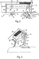
- Ambient air that is air from outside the engine compartment, is ducted to the air filter inlet 15 by a plenum chamber 19 which is provided in one of the hinge panels 5 of the engine compartment cover 3 which is generally L-shaped having two limbs 21 and 22.
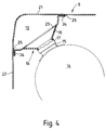
- the plenum chamber 19 is provided along the corner of this panel 5 and is thus generally triangular in cross-section as seen best in Figure 4 of the drawings. More specifically, the plenum chamber 19 is defined, on two sides, by portions of the two generally orthogonal limbs 21 and 22 of the hinge panel 5 and, on the third side or hypotenuse, by a plate 23 which has out-turned flanges 24 by which it is secured, using adhesive 25, to the undersides of the limbs 21 and 22 of said panel 5.
- the plenum plate 23 extends between two hinge brackets 26 having stepped portions to receive the ends of the plenum plate and which further also are secured to the underside of the hinge panel 5 using adhesive. It will be appreciated that the plenum plate 23 and the hinge brackets 26 may be attached to the hinge panel 5 other than by adhesive but the use of the latter ensures that there are no blemishes visible from the outside of the hinge panel which thus enhances the aesthetic appearance of the engine compartment cover.
- the plenum plate 23 is formed with an air inlet aperture 27 and an air outlet aperture 28.
- the air outlet aperture 28 is circular and has a diameter greater than that of the air inlet pipe 15 of the air filter 14 but less than the outer end of the flared portion 18 of the seal 16.
- the outer end of the flared portion 18 of the seal 16 engages around the air outlet aperture 28 of the plenum chamber 19 whereby the air inlet pipe 15 of the air filter 14 is sealed against the ingress of air from within the engine compartment, which air, in use of the vehicle, is at an elevated temperature.
- the flexibility of the seal 16 takes up any manufacturing tolerances and always ensures a satisfactory air seal around the air outlet 28 of the plenum chamber 19. It will be appreciated that this seal is automatically made and broken as the hinge panel 5 is moved to the closed and open positions, respectively.
- the air inlet 27 of the plenum chamber 19 is disposed forwardly of the radiator 11 and receives ambient air through a grid or mesh 29 provided in the limb 22 of the hinge panel 5.
- a grid or mesh 29 is provided in each of the hinge panels 5 and serves also to ventilate the engine compartment.
- it is preferable to seal that inlet 27 from the engine compartment by providing a seal over the radiator 11 which is contoured at one edge to follow the outline of the radiator 11 and contoured at the opposite edge to follow the outline of the inside surface of the hinge panels 5.
- This seal 31 is conveniently moulded from a synthetic plastics material.
- the volume of the plenum chamber 19 needs to be as large as possible in order not to starve the engine of air and to this end, the plenum plate 23 is contoured so as closely to follow the components, such as the radiator 11, adjacent thereto.
- the plenum chamber 19 has a surface area of which the major part is formed from portions of the limbs 21 and 22 of the hinge panel 5, which portions are subjected to ambient temperature. Only the plenum plate 23 is subjected to the temperature within the engine compartment and thus, air flowing through the plenum chamber 19 will be cooler than the air within the engine compartment although it may be slightly hotter than the ambient air. As already mentioned, it is important to provide air to the engine as cool as possible in order to maximise the efficiency of the engine. Tests have been carried out on the basis of running the engine, first with the seal 16 in place and then removed and the power output of the engine was found to drop by half a horse power when the seal was removed.
- the plenum chamber 19 as the duct for ambient air to the air filter 14, which air, in use of the tractor, is kept at a temperature lower than the temperature within the engine compartment, it will also be seen that this arrangement automatically removes the plenum chamber 19 from within the engine compartment when the hinge panel 5 is hinged to the open position, which is shown in Figures 2 and 3 of the drawings.
- the plenum chamber 19 in no way obscures any of the components within the engine compartment and hence, access to these components for maintenance purposes is not hindered by said plenum chamber 19.
- the plenum plate 23 also helps to rigidify the hinge panel 5 and thus reduce vibration and noise.
Landscapes
- Engineering & Computer Science (AREA)
- Chemical & Material Sciences (AREA)
- Combustion & Propulsion (AREA)
- Transportation (AREA)
- Mechanical Engineering (AREA)
- Cooling, Air Intake And Gas Exhaust, And Fuel Tank Arrangements In Propulsion Units (AREA)
- Body Structure For Vehicles (AREA)
Claims (8)
- Fahrzeug mit:- einem Motorraum, in dem ein Motor (13) und eine Luftreinigungsvorrichtung (14) befestigt sind,- einer Motorhaube (3) für den Motorraum, wobei die Motorhaube (3) eine Lufteinlaßeinrichtung (29) einschließt, und- eine Luftkanaleinrichtung in Form einer Luftkammer (19), die sich von der Nähe der Lufteinlaßeinrichtung (29) in der Motorhaube (3) zu einem Einlaß (15) der Luftreingungsvorrichtung (14) erstreckt, wobei die Luftkammer (19) einerseits einen Lufteinlaß (27) in betriebsmäßiger Verbindung mit der Lufteinlaßeinrichtung (29) in der Motorhaube (3) des Motorraums und andererseits einen Luftauslaß (28) aufweist, der mit dem Lufteinlaß (15) der Luftreinigungsvorrichtung (14) verbindbar ist,
dadurch gekennzeichnet, daß die Motorhaube (3) des Motorraumes zumindestens eine schwenkbar befestigte aufklappbare Verkleidung (5) mit zwei Schenkeln (21, 22) aufweist, die in einer allgemein L-förmigen Konfiguration angeordnet sind, und daß die Luftkammer (19) in der zumindestens einen aufklappbaren Verkleidung (5) der Motorhaube (5) des Motorraums entlang der Ecke zwischen den beiden Schenkeln (21, 22) dieser Verkleidung (5) angeordnet ist. - Fahrzeug nach Anspruch 1,
dadurch gekennzeichnet, daß die Luftkammer (19) im Querschnitt allgemein dreieckig ist und auf zwei Seiten durch die jeweiligen Schenkel (21, 22) der aufklappbaren Verkleidung (5) und auf der dritten Seite durch eine Luftkammerplatte (23) umgrenzt ist. - Fahrzeug nach Anspruch 2,
dadurch gekennzeichnet, daß die Luftkammerplatte einen derartigen Umriß aufweist, daß sie eng benachbart zu Bauteilen verläuft, die in dem Motorraum befestigt sind, so daß an jedem Punkt die Querschnittsfläche der Luftkammer (19) zu einem Maximum gemacht wird. - Fahrzeug nach Anspruch 2 oder 3,
dadurch gekennzeichnet, daß die Luftkammerplatte (23) an der Innenseite der aufklappbaren Verkleidung (5) unter Verwendung eines Klebemittels befestigt ist. - Fahrzeug nach einem der Ansprüche 2 bis 4,
dadurch gekennzeichnet, daß sich die Luftkammerplatte (23) zwischen zwei Gelenkarmen der aufklappbaren Verkleidung (5) erstreckt. - Fahrzeug nach einem der vorhergehenden Ansprüche,
dadurch gekennzeichnet, daß der Luftauslaß (28) der Luftkammer (19) die Form einer Öffnung aufweist, und daß der Lufteinlaß der Luftreinigungsvorrichtung (14) die Form eines Einlaßrohres (15) aufweist, das mit einer Dichtungseinrichtung (16) versehen ist, die um den Randteil der Luftauslaßöffnung (28) der Luftkammer (19) herum in Eingriff steht, wenn sich die aufklappbare Verkleidung (5) in der geschlossenen Stellung befindet. - Fahrzeug nach Anspruch 6,
dadurch gekennzeichnet, daß die Dichtungseinrichtung (16) eine flexible Dichtung umfaßt, die einen an dem Lufteinlaßrohr (15) der Luftreinigungsvorrichtung (14) befestigten Kragen (17) und einen sich nach außen hin erweiternden Abschnitt (18) aufweist, dessen Außenumfang mit dem Randteil des Auslasses (28) der Luftkammer (19) in Eingriff bringbar ist. - Fahrzeug nach einem der vorhergehenden Ansprüche,
dadurch gekennzeichnet, daß der Lufteinlaß (27) der Luftkammer (19) gegenüber dem Motorraum abgedichtet ist.
Priority Applications (2)
| Application Number | Priority Date | Filing Date | Title |
|---|---|---|---|
| EP19910201268 EP0515737B1 (de) | 1991-05-28 | 1991-05-28 | Luftansaugeanlage für den Motor eines Fahrzeuges |
| DE1991616681 DE69116681T2 (de) | 1991-05-28 | 1991-05-28 | Luftansaugeanlage für den Motor eines Fahrzeuges |
Applications Claiming Priority (1)
| Application Number | Priority Date | Filing Date | Title |
|---|---|---|---|
| EP19910201268 EP0515737B1 (de) | 1991-05-28 | 1991-05-28 | Luftansaugeanlage für den Motor eines Fahrzeuges |
Publications (2)
| Publication Number | Publication Date |
|---|---|
| EP0515737A1 EP0515737A1 (de) | 1992-12-02 |
| EP0515737B1 true EP0515737B1 (de) | 1996-01-24 |
Family
ID=8207672
Family Applications (1)
| Application Number | Title | Priority Date | Filing Date |
|---|---|---|---|
| EP19910201268 Expired - Lifetime EP0515737B1 (de) | 1991-05-28 | 1991-05-28 | Luftansaugeanlage für den Motor eines Fahrzeuges |
Country Status (2)
| Country | Link |
|---|---|
| EP (1) | EP0515737B1 (de) |
| DE (1) | DE69116681T2 (de) |
Families Citing this family (4)
| Publication number | Priority date | Publication date | Assignee | Title |
|---|---|---|---|---|
| USD565607S1 (en) | 2006-05-04 | 2008-04-01 | Cnh America Llc | Vehicular sprayer hood |
| US7673716B2 (en) | 2006-06-16 | 2010-03-09 | Cnh America, Llc | Drive unit enclosure assembly |
| USD560693S1 (en) | 2007-02-16 | 2008-01-29 | Cnh America Llc | Sprayer engine package enclosure |
| CN120968849B (zh) * | 2025-10-22 | 2026-01-30 | 江苏力德热交换系统有限公司 | 一种汽车发动机用的全铝散热冷却器 |
Family Cites Families (1)
| Publication number | Priority date | Publication date | Assignee | Title |
|---|---|---|---|---|
| GB2059890B (en) * | 1979-09-14 | 1983-04-07 | Brown Tractors Ltd | Tractor engine air supply means |
-
1991
- 1991-05-28 EP EP19910201268 patent/EP0515737B1/de not_active Expired - Lifetime
- 1991-05-28 DE DE1991616681 patent/DE69116681T2/de not_active Expired - Fee Related
Also Published As
| Publication number | Publication date |
|---|---|
| DE69116681T2 (de) | 1996-07-04 |
| DE69116681D1 (de) | 1996-03-07 |
| EP0515737A1 (de) | 1992-12-02 |
Similar Documents
| Publication | Publication Date | Title |
|---|---|---|
| US5199522A (en) | Air inlet for vehicle engine | |
| US5119718A (en) | Ventilating arrangement for the cab of a vehicle | |
| US4932490A (en) | Engine air induction system with air cleaner in hood | |
| CA1221918A (en) | Atmosphere control arrangement for an operator enclosure | |
| US4689060A (en) | Cab engine air intake system and method | |
| US5660243A (en) | Air flow, atmospheric particle, and environmental element diverter system | |
| CA2299828C (en) | Engine enclosure with cooling air baffle | |
| US5207187A (en) | Air cooling system for a vertical engine | |
| US3636684A (en) | Engine enclosure for a harvesting machine | |
| CA2015099A1 (en) | Motor vehicle engine air intake system including moisture elimination apparatus | |
| US6837324B2 (en) | Engine enclosure | |
| GB2054133A (en) | Noiseless ventilation of vehicles | |
| US20040262061A1 (en) | Work vehicle hood | |
| US7575081B2 (en) | Work vehicle | |
| US7418994B2 (en) | Fan shroud with integral hood seal | |
| JPH0440971Y2 (de) | ||
| GB2073116A (en) | Off-highway vehicle particularly an agricultural tractor | |
| EP0515737A1 (de) | Luftansaugeanlage für den Motor eines Fahrzeuges | |
| JP4106737B2 (ja) | 自動車の前部車体構造 | |
| US8230959B2 (en) | Folding air intake scoop | |
| JP2003104049A (ja) | 車両運転台用の空気ろ過システム | |
| KR880013721A (ko) | 농업용 트랙터의 엔진 냉각구조 | |
| JP3551695B2 (ja) | 過給機付エンジンの吸気配管構造 | |
| JP2000335223A (ja) | トラクタの空調装置構造 | |
| JPH0353927Y2 (de) |
Legal Events
| Date | Code | Title | Description |
|---|---|---|---|
| PUAI | Public reference made under article 153(3) epc to a published international application that has entered the european phase |
Free format text: ORIGINAL CODE: 0009012 |
|
| AK | Designated contracting states |
Kind code of ref document: A1 Designated state(s): DE ES FR GB IT |
|
| RAP3 | Party data changed (applicant data changed or rights of an application transferred) |
Owner name: NEW HOLLAND FORD LIMITED |
|
| 17P | Request for examination filed |
Effective date: 19930604 |
|
| 17Q | First examination report despatched |
Effective date: 19941209 |
|
| RAP1 | Party data changed (applicant data changed or rights of an application transferred) |
Owner name: NEW HOLLAND U.K. LIMITED |
|
| GRAA | (expected) grant |
Free format text: ORIGINAL CODE: 0009210 |
|
| AK | Designated contracting states |
Kind code of ref document: B1 Designated state(s): DE ES FR GB IT |
|
| PG25 | Lapsed in a contracting state [announced via postgrant information from national office to epo] |
Ref country code: ES Free format text: THE PATENT HAS BEEN ANNULLED BY A DECISION OF A NATIONAL AUTHORITY Effective date: 19960124 |
|
| REF | Corresponds to: |
Ref document number: 69116681 Country of ref document: DE Date of ref document: 19960307 |
|
| ET | Fr: translation filed | ||
| ITF | It: translation for a ep patent filed | ||
| PLBE | No opposition filed within time limit |
Free format text: ORIGINAL CODE: 0009261 |
|
| STAA | Information on the status of an ep patent application or granted ep patent |
Free format text: STATUS: NO OPPOSITION FILED WITHIN TIME LIMIT |
|
| 26N | No opposition filed | ||
| REG | Reference to a national code |
Ref country code: GB Ref legal event code: IF02 |
|
| REG | Reference to a national code |
Ref country code: FR Ref legal event code: CD |
|
| PGFP | Annual fee paid to national office [announced via postgrant information from national office to epo] |
Ref country code: GB Payment date: 20060330 Year of fee payment: 16 |
|
| PGFP | Annual fee paid to national office [announced via postgrant information from national office to epo] |
Ref country code: FR Payment date: 20060404 Year of fee payment: 16 |
|
| PGFP | Annual fee paid to national office [announced via postgrant information from national office to epo] |
Ref country code: DE Payment date: 20060520 Year of fee payment: 16 |
|
| PGFP | Annual fee paid to national office [announced via postgrant information from national office to epo] |
Ref country code: IT Payment date: 20060531 Year of fee payment: 16 |
|
| GBPC | Gb: european patent ceased through non-payment of renewal fee |
Effective date: 20070528 |
|
| REG | Reference to a national code |
Ref country code: FR Ref legal event code: ST Effective date: 20080131 |
|
| PG25 | Lapsed in a contracting state [announced via postgrant information from national office to epo] |
Ref country code: DE Free format text: LAPSE BECAUSE OF NON-PAYMENT OF DUE FEES Effective date: 20071201 |
|
| PG25 | Lapsed in a contracting state [announced via postgrant information from national office to epo] |
Ref country code: GB Free format text: LAPSE BECAUSE OF NON-PAYMENT OF DUE FEES Effective date: 20070528 |
|
| PG25 | Lapsed in a contracting state [announced via postgrant information from national office to epo] |
Ref country code: FR Free format text: LAPSE BECAUSE OF NON-PAYMENT OF DUE FEES Effective date: 20070531 |
|
| PG25 | Lapsed in a contracting state [announced via postgrant information from national office to epo] |
Ref country code: IT Free format text: LAPSE BECAUSE OF NON-PAYMENT OF DUE FEES Effective date: 20070528 |