EP0516004A2 - Dispositif hydromécanique de sécurité pour charrues réversibles et charrues pour labour en planches - Google Patents
Dispositif hydromécanique de sécurité pour charrues réversibles et charrues pour labour en planches Download PDFInfo
- Publication number
- EP0516004A2 EP0516004A2 EP92108723A EP92108723A EP0516004A2 EP 0516004 A2 EP0516004 A2 EP 0516004A2 EP 92108723 A EP92108723 A EP 92108723A EP 92108723 A EP92108723 A EP 92108723A EP 0516004 A2 EP0516004 A2 EP 0516004A2
- Authority
- EP
- European Patent Office
- Prior art keywords
- plow
- hydromechanical
- overload protection
- spindle
- bed
- Prior art date
- Legal status (The legal status is an assumption and is not a legal conclusion. Google has not performed a legal analysis and makes no representation as to the accuracy of the status listed.)
- Withdrawn
Links
Images

Classifications
-
- A—HUMAN NECESSITIES
- A01—AGRICULTURE; FORESTRY; ANIMAL HUSBANDRY; HUNTING; TRAPPING; FISHING
- A01B—SOIL WORKING IN AGRICULTURE OR FORESTRY; PARTS, DETAILS, OR ACCESSORIES OF AGRICULTURAL MACHINES OR IMPLEMENTS, IN GENERAL
- A01B61/00—Devices for, or parts of, agricultural machines or implements for preventing overstrain
- A01B61/04—Devices for, or parts of, agricultural machines or implements for preventing overstrain of the connection between tools and carrier beam or frame
- A01B61/044—Devices for, or parts of, agricultural machines or implements for preventing overstrain of the connection between tools and carrier beam or frame the connection enabling a yielding pivoting movement around a substantially horizontal and transverse axis
- A01B61/046—Devices for, or parts of, agricultural machines or implements for preventing overstrain of the connection between tools and carrier beam or frame the connection enabling a yielding pivoting movement around a substantially horizontal and transverse axis the device including an energy accumulator for restoring the tool to its working position
- A01B61/048—Devices for, or parts of, agricultural machines or implements for preventing overstrain of the connection between tools and carrier beam or frame the connection enabling a yielding pivoting movement around a substantially horizontal and transverse axis the device including an energy accumulator for restoring the tool to its working position the connection or the energy accumulator being active in two opposite directions, e.g. for reversible plows
Definitions
- the invention relates to a hydromechanical overload protection for bed and rotary plows for use in tillage.
- overload protection devices which implement the lifting and inserting of the plow bodies by means of a hydraulic cylinder arranged in the tubular shaft. It is also known to support the hydraulic cylinder on the plow frame by means of a toggle lever system.
- EP-PS 37 848 shows a similar solution with which a relatively compact, light overload protection is known.
- the swivel joint of the spindle is arranged below the plow frame.
- the full support force of the hydraulic cylinder is applied to the toggle lever system not only in the working but also in the transport position of the plow body.
- an adjustable stop connected to the plow frame is arranged beneath the grind to fix the transport position, since this would otherwise be deflected downwards.
- the toggle lever system At its junction with the plow frame, the toggle lever system has a device for setting the triggering force for the overload protection, which additionally increases the construction effort.
- the object of the invention is therefore to provide a compact and functionally reliable hydromechanical overload protection which can be used equally for bed and rotary plows.
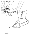
- the lever system consists of a pressure lever and a pressure plate arranged approximately in the middle.
- the pressure plate is connected in a joint to the plow frame and the pressure lever is articulated at the upper end of the plow.
- the pressure lever has a contact and abrasion surface with the piston on the other hand, it rests against a stop arranged on the spindle.
- a guide slot is arranged on both sides of the spindle, which serves to receive and guide guide elements fastened on both piston sides.
- the hinge pin used to connect the pressure plate and the pressure lever is guided in an elongated hole arranged on the pressure plate.
- the stop attached to the spindle is adjustable by means of an adjusting screw.
- a fender covering the moving parts of the overload safety device is arranged on the shaft.
- the plow body In the working position, the plow body is held in its lower end position by means of the lever system. Since the pressure lever is in contact with the stop even in the transport position, the cylinder force is supported there. Thus, the grindel only hangs on the pressure bracket with its own weight and the weight of the plow body, which significantly reduces its load.
- the spindle is adjusted in its zero position by means of the adjustable stop.
- the grindel moves upwards around its swivel joint.
- the pressure lever is moved backwards through the pressure plate.
- the piston which is horizontally guided by means of the guide elements in the elongated guide holes, is pushed backwards, the pressure lever rolling on the contact and rolling surface on the piston surface.
- the cylinder is compressed. After overcoming the obstacle, the cylinder pushes the pressure lever back into its starting position and thus the plow body into its working position.
- the piston 14 is held with its guide elements designed as bolts 17 in the guide elongated holes 18 on both sides of the spindle 2.
- the hydraulic cylinder 6 is fastened in the holder 19 on the spindle 2.
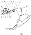
- the overload safety device is equipped with a second lever system 9 and a second stop 15, which are arranged below the plane of symmetry 5 and are designed symmetrically to the first lever system 9 or to the first stop 15.
- a second lever system 9 and a second stop 15 which are arranged below the plane of symmetry 5 and are designed symmetrically to the first lever system 9 or to the first stop 15.
- an elongated hole 20 for guiding the corresponding hinge pin 11 is arranged on each pressure bracket 8 (FIG. 3).
- a fender 21 covering the moving parts of the overload protection device is arranged on the shaft 2.
- the plow body 1 In the working position, the plow body 1 is in its lower end position and the shaft 2 is held on the plow frame 3 by the pressure lever 7 resting against the stop 15 via the pressure plate 8. The end position of the spindle 2 is adjusted by the vertical displacement of the stop 15 by means of the adjusting screw 16.
- the principle of operation of the overload protection for the reversible plow is basically the same. Only the hinge pin 11 of the lower lever system 9 is guided to the rear when the plow body 1 is pivoted upward in the elongated hole 20 of the lower pressure bracket 8, during which time it moves forward again when the plow body 1 is set down.
Landscapes
- Life Sciences & Earth Sciences (AREA)
- Engineering & Computer Science (AREA)
- Mechanical Engineering (AREA)
- Soil Sciences (AREA)
- Environmental Sciences (AREA)
- Lifting Devices For Agricultural Implements (AREA)
Applications Claiming Priority (2)
| Application Number | Priority Date | Filing Date | Title |
|---|---|---|---|
| DE4117947 | 1991-05-31 | ||
| DE19914117947 DE4117947A1 (de) | 1991-05-31 | 1991-05-31 | Hydromechanische ueberlastsicherung fuer beet- und drehpfluege |
Publications (2)
| Publication Number | Publication Date |
|---|---|
| EP0516004A2 true EP0516004A2 (fr) | 1992-12-02 |
| EP0516004A3 EP0516004A3 (en) | 1993-06-09 |
Family
ID=6432945
Family Applications (1)
| Application Number | Title | Priority Date | Filing Date |
|---|---|---|---|
| EP19920108723 Withdrawn EP0516004A3 (en) | 1991-05-31 | 1992-05-23 | Hydromechanical overload safety device for conventional and reversible ploughs |
Country Status (4)
| Country | Link |
|---|---|
| EP (1) | EP0516004A3 (fr) |
| DE (1) | DE4117947A1 (fr) |
| HU (1) | HUT65878A (fr) |
| PL (1) | PL294722A1 (fr) |
Cited By (5)
| Publication number | Priority date | Publication date | Assignee | Title |
|---|---|---|---|---|
| WO1994016546A1 (fr) * | 1993-01-19 | 1994-08-04 | Kverneland Klepp As | Mecanisme de protection contre les surcharges pour un timon de charrue tubulaire |
| EP1053667A1 (fr) | 1999-05-21 | 2000-11-22 | Sicil Tiller S.n.c. dei | Corps de charrue pour charrue réversible hydropneumatique |
| US7823651B2 (en) | 2008-03-18 | 2010-11-02 | Cnh Canada, Ltd. | Trip mechanism for a ground working tool |
| EP2425696A1 (fr) * | 2010-09-06 | 2012-03-07 | Kuhn-Huard S.A. | Charrue avec un dispositif pour soulever au moins un age |
| CN115104394A (zh) * | 2022-06-23 | 2022-09-27 | 广东皓耘科技有限公司 | 一种防过载保护装置及翻转犁 |
Families Citing this family (1)
| Publication number | Priority date | Publication date | Assignee | Title |
|---|---|---|---|---|
| DE102005020921B3 (de) * | 2005-05-04 | 2007-01-25 | Lemken Gmbh & Co. Kg | Drehpflug mit Überlastsicherung |
Family Cites Families (5)
| Publication number | Priority date | Publication date | Assignee | Title |
|---|---|---|---|---|
| FR2419000A1 (fr) * | 1978-03-06 | 1979-10-05 | Viaud Sa | Appareil aratoire pourvu d'un dispositif de securite pour ses outils |
| DE2834935A1 (de) * | 1978-08-09 | 1980-02-21 | Bayerische Pflugfabrik Gmbh | Ueberlastsicherung fuer beet- und volldrehpfluege |
| DE8009847U1 (de) * | 1980-04-10 | 1980-07-24 | Rabewerk Heinrich Clausing, 4515 Bad Essen | Steinsicherung fuer beetpfluege |
| DE3505273A1 (de) * | 1985-02-15 | 1986-08-21 | Eberhardt Pflugfabrik GmbH, 8871 Waldstetten | Stein- und ueberlastsicherung fuer pfluege |
| GB8529752D0 (en) * | 1985-12-03 | 1986-01-08 | Ransomes Sims & Jefferies Plc | Reversible ploughs |
-
1991
- 1991-05-31 DE DE19914117947 patent/DE4117947A1/de not_active Withdrawn
-
1992
- 1992-05-12 HU HU9201573A patent/HUT65878A/hu unknown
- 1992-05-23 EP EP19920108723 patent/EP0516004A3/de not_active Withdrawn
- 1992-05-28 PL PL29472292A patent/PL294722A1/xx unknown
Cited By (6)
| Publication number | Priority date | Publication date | Assignee | Title |
|---|---|---|---|---|
| WO1994016546A1 (fr) * | 1993-01-19 | 1994-08-04 | Kverneland Klepp As | Mecanisme de protection contre les surcharges pour un timon de charrue tubulaire |
| EP1053667A1 (fr) | 1999-05-21 | 2000-11-22 | Sicil Tiller S.n.c. dei | Corps de charrue pour charrue réversible hydropneumatique |
| US7823651B2 (en) | 2008-03-18 | 2010-11-02 | Cnh Canada, Ltd. | Trip mechanism for a ground working tool |
| EP2425696A1 (fr) * | 2010-09-06 | 2012-03-07 | Kuhn-Huard S.A. | Charrue avec un dispositif pour soulever au moins un age |
| FR2964292A1 (fr) * | 2010-09-06 | 2012-03-09 | Kuhn Huard Sa | Charrue avec un dispositif pour soulever au moins un age |
| CN115104394A (zh) * | 2022-06-23 | 2022-09-27 | 广东皓耘科技有限公司 | 一种防过载保护装置及翻转犁 |
Also Published As
| Publication number | Publication date |
|---|---|
| DE4117947A1 (de) | 1992-12-03 |
| EP0516004A3 (en) | 1993-06-09 |
| PL294722A1 (en) | 1992-12-14 |
| HUT65878A (en) | 1994-07-28 |
| HU9201573D0 (en) | 1992-08-28 |
Similar Documents
| Publication | Publication Date | Title |
|---|---|---|
| EP0628236B1 (fr) | Dispositif réglable en hauteur | |
| DE7523511U (de) | Aufsatteldrehpflug mit einer ueberlastsicherung der verbindung zwischen bodenbearbeitungswerkzeugen und ihren tragrahmen | |
| DE1557738C3 (fr) | ||
| DE1557738B2 (de) | Gesteinauslöser für einen an einem Schlepper anbaubaren Pflug | |
| EP0516004A2 (fr) | Dispositif hydromécanique de sécurité pour charrues réversibles et charrues pour labour en planches | |
| EP0516005B1 (fr) | Charrue comportant un dispositif de sécurité pour l'age | |
| DE2633428A1 (de) | Anbauvorrichtung zum anbau von geraeten, insbesondere schneeraeumgeraeten | |
| DE2745446C2 (de) | Einrichtung zur Niveausteuerung einer Gewinnungsmaschine, insbesondere eines Hobels | |
| DE3130280A1 (de) | Hoehenverstelleinrichtung fuer sitze, insbesondere kraftfahrzeugsitze | |
| EP0012997B1 (fr) | Charrue réversible | |
| DE69305429T2 (de) | Pendelstütz- und Nachlaufrad für Drehpflüge | |
| DE3500221A1 (de) | Hoehenverstellbares abstuetzgeraet, insbesondere sattelaufliegerstuetze | |
| EP1008550B1 (fr) | Agencement mécanique pour limiter le mouvement de plate-formes de travail | |
| EP0562176A1 (fr) | Charrue semiportée ou tractée | |
| EP0037848A1 (fr) | Dispositif de sécurité pour charrues simples | |
| DE2330764C2 (de) | Einrichtung zur Niveausteuerung einer Gewinnungsmaschine, insbesondere eines Hobels | |
| AT392993B (de) | Schneepflug | |
| DE1221833B (de) | Seitenabstuetzung fuer die unteren Hubwerkslenker eines Dreipunktgestaenges an Ackerschleppern od. dgl. | |
| DE69200309T2 (de) | Pflug mit einer Vorrichtung zur Regelung der Neigung und des Seitengriffs. | |
| DE2227406A1 (de) | Fahrbare drehleiter | |
| DE3401230A1 (de) | Sitzunterbau mit einer laufschienenanordnung | |
| AT397594B (de) | Steinsicherungsvorrichtung für drehpflüge | |
| DE9315877U1 (de) | Heuwerbungsmaschine | |
| EP0440114A2 (fr) | Dispositif d'attelage des outils de nettoyage de routes ou travail de sol aux véhicules | |
| DE69421165T2 (de) | Rohrpflugrahmenüberlastsicherung |
Legal Events
| Date | Code | Title | Description |
|---|---|---|---|
| PUAI | Public reference made under article 153(3) epc to a published international application that has entered the european phase |
Free format text: ORIGINAL CODE: 0009012 |
|
| AK | Designated contracting states |
Kind code of ref document: A2 Designated state(s): AT CH DE DK FR GB IT LI NL SE |
|
| PUAL | Search report despatched |
Free format text: ORIGINAL CODE: 0009013 |
|
| AK | Designated contracting states |
Kind code of ref document: A3 Designated state(s): AT CH DE DK FR GB IT LI NL SE |
|
| STAA | Information on the status of an ep patent application or granted ep patent |
Free format text: STATUS: THE APPLICATION IS DEEMED TO BE WITHDRAWN |
|
| 18D | Application deemed to be withdrawn |
Effective date: 19931210 |