EP1053667A1 - Corps de charrue pour charrue réversible hydropneumatique - Google Patents
Corps de charrue pour charrue réversible hydropneumatique Download PDFInfo
- Publication number
- EP1053667A1 EP1053667A1 EP00830361A EP00830361A EP1053667A1 EP 1053667 A1 EP1053667 A1 EP 1053667A1 EP 00830361 A EP00830361 A EP 00830361A EP 00830361 A EP00830361 A EP 00830361A EP 1053667 A1 EP1053667 A1 EP 1053667A1
- Authority
- EP
- European Patent Office
- Prior art keywords
- fork
- coupling means
- frame
- ploughing
- hydropneumatic
- Prior art date
- Legal status (The legal status is an assumption and is not a legal conclusion. Google has not performed a legal analysis and makes no representation as to the accuracy of the status listed.)
- Withdrawn
Links
- 230000002441 reversible effect Effects 0.000 title claims abstract description 7
- 230000008878 coupling Effects 0.000 claims abstract description 27
- 238000010168 coupling process Methods 0.000 claims abstract description 27
- 238000005859 coupling reaction Methods 0.000 claims abstract description 27
- IJGRMHOSHXDMSA-UHFFFAOYSA-N Atomic nitrogen Chemical compound N#N IJGRMHOSHXDMSA-UHFFFAOYSA-N 0.000 description 2
- 239000002699 waste material Substances 0.000 description 2
- 238000007792 addition Methods 0.000 description 1
- 230000008859 change Effects 0.000 description 1
- 239000012530 fluid Substances 0.000 description 1
- 230000007246 mechanism Effects 0.000 description 1
- 230000004048 modification Effects 0.000 description 1
- 238000012986 modification Methods 0.000 description 1
- 229910052757 nitrogen Inorganic materials 0.000 description 1
- 238000011084 recovery Methods 0.000 description 1
- 238000003466 welding Methods 0.000 description 1
Images

Classifications
-
- A—HUMAN NECESSITIES
- A01—AGRICULTURE; FORESTRY; ANIMAL HUSBANDRY; HUNTING; TRAPPING; FISHING
- A01B—SOIL WORKING IN AGRICULTURE OR FORESTRY; PARTS, DETAILS, OR ACCESSORIES OF AGRICULTURAL MACHINES OR IMPLEMENTS, IN GENERAL
- A01B61/00—Devices for, or parts of, agricultural machines or implements for preventing overstrain
- A01B61/04—Devices for, or parts of, agricultural machines or implements for preventing overstrain of the connection between tools and carrier beam or frame
- A01B61/044—Devices for, or parts of, agricultural machines or implements for preventing overstrain of the connection between tools and carrier beam or frame the connection enabling a yielding pivoting movement around a substantially horizontal and transverse axis
- A01B61/046—Devices for, or parts of, agricultural machines or implements for preventing overstrain of the connection between tools and carrier beam or frame the connection enabling a yielding pivoting movement around a substantially horizontal and transverse axis the device including an energy accumulator for restoring the tool to its working position
- A01B61/048—Devices for, or parts of, agricultural machines or implements for preventing overstrain of the connection between tools and carrier beam or frame the connection enabling a yielding pivoting movement around a substantially horizontal and transverse axis the device including an energy accumulator for restoring the tool to its working position the connection or the energy accumulator being active in two opposite directions, e.g. for reversible plows
Definitions
- This invention relates to a ploughing body adaptable to a non stop reversible hydropneumatic plough of the ASI 35/40/45/50 REV kind.
- a plough of this kind bear a series of beams ("beam” simply means a plough drawbar to which frontally a yoke is hitched).
- beam simply means a plough drawbar to which frontally a yoke is hitched.
- the plough is provided with a hydropneumatic circuit by which hydraulic cylinders mounted on the plough are fed.
- These hydraulic cylinders have several duties, such as to orient the frame with respect to the direction of movement of the tractor to which the plough is connected, to invert the shares in operation, to activate, in case the "non stop” or safety system is of the hydropneumatic kind, the rotation of a couple of shares upwards, when the plough comes up against an obstacle, that would be insuperable with the shares in their usual working position.
- the invention is directed in particular to this specific kind of safety system.
- the present hydropneumatic safety systems adopt several devices to allow the upward rotation of the beam supporting a share that comes up against an obstacle.
- a coupling which is operated by means of hydraulic cylinders.
- This coupling through particular mechanisms allows a pair of shares to be detached in case of their failure. This involves a great effort to put back in operation a pair of shares on the plough.
- a pair of coupling pins are provided. Only one of these coupling pins, for each direction of movement of the tractor, can be broken when the moment on the share exceeds a preset value and then a maximum set pressure of a hydraulic cylinder is surpassed. Once the broken coupling pin is replaced after crossing the obstacle, the plough is able to work again.
- this last safety system doesn't involve the recovery of the pair of shares from the soul, it causes difficulties to a worker and useless waste of time.
- An object of the present invention is to avoid a stop of the ploughing when an obstacle is reached and crossed which involves that the maximum set pressure inside the hydraulic cylinder, that connects a beam to the frame of the plough, is surpassed.
- a ploughing body adaptable to a non stop reversible hydropneumatic plough of the ASI 35/40/45/50 REV kind including a beam, supporting shares with right hand mouldboard and left hand mouldboard respectively, joined with similar other beams of the same number of ploughing bodies to a frame that is connected through an articulation H-beam to a three-point attachment of a tractor and provided with a hydropneumatic circuit, characterised in that said beam like an anchor comprises a central shank diverging rearwards, downwards and upwards, in a couple of share holder arms and frontally provided with a fork, a couple of fulcrums, the one fulcrum being placed over the other, being mounted on said fork with relative coupling means fixed to said frame; at least a hydraulic cylinder, operatively connected to said hydropneumatic circuit and mounted between said beam and said coupling means, respectively, of said couple applying a preset strut force between said fork and said
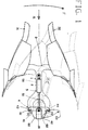
- a ploughing body according to the invention is shown in which a beam is denoted in general as 1, a plough frame as 10, a pair of hydraulic cylinders as 5 and 500, respectively (Figure 2), and coupling means as 6 and 600 respectively, that connect the beam 1 to the frame 10.
- the beam 1 is shaped as an anchor having a central shank 2.
- the central shank 2 is divergent rearwards, downwards and upwards, into a couple of arms in general denoted as 3.
- Each arm of the couple 3 supports a share 31 having a right hand mouldboard and a share 32 having a left hand mouldboard. These shares work alternatively in each ploughing run, as explained below.
- the shank 2 is frontally provided with a fork 4. On the ends 41, 42 of the fork 4 there are a couple of fulcrums P1, P2, the one fulcrum being placed over the other, when the fork 4 is connected to the coupling means 6, 600 fixed to the frame 10.
- the fork ends 41, 42 are sandwiched between the coupling means 6, 600.
- the coupling means 6, 600 suitably fixed to the frame 10 with a ⁇ shaped profile, have sides 60, 62 joined with the frame 10, e.g. by welding, and a core ending in two hook shaped ends 61, 63.
- These ends 61, 63 which are made in both the coupling means 6, 600 in a mirror-image relationship, form seats for two pins 43, 44 perpendicularly projecting from the ends of the fork 4 of the beam 1.
- the ends 61, 63 of the coupling means 6, 600, together with the pins 43, 44, constitute the fulcrums P1, P2 to rotate the beam 1 to the frame 10, as explained below.
- the connection between the fork 4 and the coupling means 6, 600 can be made also in a different way, for example through pins integral with the coupling means and hook shaped ends made on the fork.
- the beam 1 pivoted in the fulcrum P1 tends to rotate upwards as indicated by an arrow F, until a position represented with a dash line, that allows the obstacle (normally of a height of about 0.55 m with respect to the point of the share) to be crossed.
- the obstacle normally of a height of about 0.55 m with respect to the point of the share
- the work pressure inside the cylinder is restored and the pin 44 returns to its seat in the end 63 of the coupling means 6, 600, when the beam 1 rotates in the direction opposed to that indicated by the arrow F.
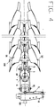
- FIG 4 it is shown how the beam 1, together with the similar not numbered beams, is mounted through the frame 10 on the plough.
- the frame 10 is articulated by means of an articulation H-beam 7 to a three-point attachment 8 of a tractor.
- the H-beam 7 is swinging through a spindle 80 on the attachment 8.
- An inversion cylinder 9 allows the H-beam 7 to be rotated about 180 degrees with a result that the share 32 with left hand mouldboard downwards, i.e. in a work position.
- the piston rod of the inversion cylinder 9 is engaged with a pivot 91 parallely offset in the horizontal plane with respect to the axis of the spindle 80.
- the frame 10 can be oriented in the desired angle to the three-point attachment 8 by means of suitable hydraulic cylinders (not shown).
- the plough has a bearing wheel 100 to keep the distance with the ground.
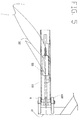
- FIG 5 a change in the ploughing body according the invention is shown.
- the central shank of the beam has a conformation of a box shaped structure 110 having only one hydraulic cylinder 55 contained inside.
- the side view remains substantially the same to that in figure 1, as well as the operation, no longer explained.
Landscapes
- Life Sciences & Earth Sciences (AREA)
- Engineering & Computer Science (AREA)
- Mechanical Engineering (AREA)
- Soil Sciences (AREA)
- Environmental Sciences (AREA)
- Manufacturing Of Micro-Capsules (AREA)
- Medicinal Preparation (AREA)
- Fluid-Pressure Circuits (AREA)
Applications Claiming Priority (2)
| Application Number | Priority Date | Filing Date | Title |
|---|---|---|---|
| ITRM990320 | 1999-05-21 | ||
| IT1999RM000320A IT1306144B1 (it) | 1999-05-21 | 1999-05-21 | Corpo arante di aratro idropneumatico reversibile. |
Publications (1)
| Publication Number | Publication Date |
|---|---|
| EP1053667A1 true EP1053667A1 (fr) | 2000-11-22 |
Family
ID=11406776
Family Applications (1)
| Application Number | Title | Priority Date | Filing Date |
|---|---|---|---|
| EP00830361A Withdrawn EP1053667A1 (fr) | 1999-05-21 | 2000-05-19 | Corps de charrue pour charrue réversible hydropneumatique |
Country Status (2)
| Country | Link |
|---|---|
| EP (1) | EP1053667A1 (fr) |
| IT (1) | IT1306144B1 (fr) |
Citations (8)
| Publication number | Priority date | Publication date | Assignee | Title |
|---|---|---|---|---|
| FR2320041A1 (fr) * | 1975-08-05 | 1977-03-04 | Baert Jerome | Mecanisme de deviation elastique pour machine pour travailler le sol, notamment pour charrue brabant |
| FR2386241A2 (fr) * | 1975-08-05 | 1978-11-03 | Baert Jerome | Mecanisme de deviation elastique pour machine pour travailler le sol, notamment pour charrue brabant |
| DE2930742B1 (de) * | 1979-07-28 | 1980-05-08 | Niemeyer Gmbh & Co Kg Soehne | UEberlast-Sicherheitseinrichtung fuer Pfluege |
| FR2470521A1 (fr) * | 1979-11-29 | 1981-06-12 | Thieme Et Cie Ets | Dispositif de charrue |
| DE3124314A1 (de) * | 1981-06-20 | 1983-01-05 | H. Niemeyer Söhne GmbH & Co KG, 4446 Hörstel | Ueberlast-sicherheitsvorrichtung fuer pfluege |
| EP0516004A2 (fr) | 1991-05-31 | 1992-12-02 | Bodenbearbeitungsgeräte Leipzig AG | Dispositif hydromécanique de sécurité pour charrues réversibles et charrues pour labour en planches |
| GB2259839A (en) | 1991-09-24 | 1993-03-31 | Kverneland Klepp As | Plough body position control device |
| DE19652615C1 (de) | 1996-12-18 | 1998-03-12 | Eberhardt Maschinenfabrik Gmbh | Hydraulische Überlastsicherung für Pflüge |
-
1999
- 1999-05-21 IT IT1999RM000320A patent/IT1306144B1/it active
-
2000
- 2000-05-19 EP EP00830361A patent/EP1053667A1/fr not_active Withdrawn
Patent Citations (8)
| Publication number | Priority date | Publication date | Assignee | Title |
|---|---|---|---|---|
| FR2320041A1 (fr) * | 1975-08-05 | 1977-03-04 | Baert Jerome | Mecanisme de deviation elastique pour machine pour travailler le sol, notamment pour charrue brabant |
| FR2386241A2 (fr) * | 1975-08-05 | 1978-11-03 | Baert Jerome | Mecanisme de deviation elastique pour machine pour travailler le sol, notamment pour charrue brabant |
| DE2930742B1 (de) * | 1979-07-28 | 1980-05-08 | Niemeyer Gmbh & Co Kg Soehne | UEberlast-Sicherheitseinrichtung fuer Pfluege |
| FR2470521A1 (fr) * | 1979-11-29 | 1981-06-12 | Thieme Et Cie Ets | Dispositif de charrue |
| DE3124314A1 (de) * | 1981-06-20 | 1983-01-05 | H. Niemeyer Söhne GmbH & Co KG, 4446 Hörstel | Ueberlast-sicherheitsvorrichtung fuer pfluege |
| EP0516004A2 (fr) | 1991-05-31 | 1992-12-02 | Bodenbearbeitungsgeräte Leipzig AG | Dispositif hydromécanique de sécurité pour charrues réversibles et charrues pour labour en planches |
| GB2259839A (en) | 1991-09-24 | 1993-03-31 | Kverneland Klepp As | Plough body position control device |
| DE19652615C1 (de) | 1996-12-18 | 1998-03-12 | Eberhardt Maschinenfabrik Gmbh | Hydraulische Überlastsicherung für Pflüge |
Also Published As
| Publication number | Publication date |
|---|---|
| ITRM990320A0 (it) | 1999-05-21 |
| IT1306144B1 (it) | 2001-05-30 |
| ITRM990320A1 (it) | 2000-11-21 |
Similar Documents
| Publication | Publication Date | Title |
|---|---|---|
| US8347976B2 (en) | Hitch device for a working vehicle | |
| CA1161212A (fr) | Charniere | |
| SU1286101A3 (ru) | Механизм креплени дл зацеплени землеобрабатывающего оборудовани к т гачу | |
| EP3035786B1 (fr) | Système de fixation destiné à un accessoire | |
| US5661917A (en) | Civil engineering works machine in which the working tool is mounted at the end of an articulated arm | |
| CA2802409A1 (fr) | Stabilisateur de tringlerie de tracteur agricole | |
| US4194756A (en) | Lifting device and associated structure | |
| NO153864B (no) | Anordning ved plogramme for frontmontert snoeplog. | |
| US5366336A (en) | Leveling rod assembly coupled between towed implement hitch and ground wheel axle | |
| EP1070455A2 (fr) | Structure de bras | |
| NO165821B (no) | Anordning til innstilling av avstanden mellom jordsmonn-bearbeidelsesverktoey. | |
| US5135057A (en) | Agricultural implement lifting mechanism | |
| US4103796A (en) | Bucket attachment for tractors | |
| NL8403920A (nl) | Omkeermechanisme voor een ploeg. | |
| EP1800529B2 (fr) | Faucheuse | |
| CA2199162C (fr) | Dispositif d'accouplement | |
| US5197552A (en) | Collapsible bar assembly for agricultural equipment | |
| US3550690A (en) | Swinging beam plow | |
| EP2189053B1 (fr) | Machine agricole dotée d'une protection contre les impacts | |
| CZ2013327A3 (cs) | Zařízení ke sklápění pracovního nástroje zemědělského stroje | |
| EP2662493B1 (fr) | Cadre de support d'un dispositif de maintenance routière | |
| EP1800528A1 (fr) | Faucheuse | |
| US4240509A (en) | Tool mounting assembly for soil tilling implement | |
| EP0680250B1 (fr) | Mecanisme de protection contre les surcharges pour un timon de charrue tubulaire | |
| US2722877A (en) | Releasable plow standard |
Legal Events
| Date | Code | Title | Description |
|---|---|---|---|
| PUAI | Public reference made under article 153(3) epc to a published international application that has entered the european phase |
Free format text: ORIGINAL CODE: 0009012 |
|
| AK | Designated contracting states |
Kind code of ref document: A1 Designated state(s): AT BE CH CY DE DK ES FI FR GB GR IE IT LI LU MC NL PT SE |
|
| AX | Request for extension of the european patent |
Free format text: AL;LT;LV;MK;RO;SI |
|
| 17P | Request for examination filed |
Effective date: 20010426 |
|
| AKX | Designation fees paid |
Free format text: AT BE CH CY DE DK ES FI FR GB GR IE IT LI LU MC NL PT SE |
|
| 17Q | First examination report despatched |
Effective date: 20010718 |
|
| TPAD | Observations filed by third parties |
Free format text: ORIGINAL CODE: EPIDOS TIPA |
|
| STAA | Information on the status of an ep patent application or granted ep patent |
Free format text: STATUS: THE APPLICATION IS DEEMED TO BE WITHDRAWN |
|
| 18D | Application deemed to be withdrawn |
Effective date: 20030821 |