EP0516091A2 - Steuerungsverfahren eines Thermo-Druckkopfes eines Thermo-Farbdruckers - Google Patents
Steuerungsverfahren eines Thermo-Druckkopfes eines Thermo-Farbdruckers Download PDFInfo
- Publication number
- EP0516091A2 EP0516091A2 EP92108963A EP92108963A EP0516091A2 EP 0516091 A2 EP0516091 A2 EP 0516091A2 EP 92108963 A EP92108963 A EP 92108963A EP 92108963 A EP92108963 A EP 92108963A EP 0516091 A2 EP0516091 A2 EP 0516091A2
- Authority
- EP
- European Patent Office
- Prior art keywords
- modulation density
- gate
- given
- density
- modulation
- Prior art date
- Legal status (The legal status is an assumption and is not a legal conclusion. Google has not performed a legal analysis and makes no representation as to the accuracy of the status listed.)
- Withdrawn
Links
Images



Classifications
-
- B—PERFORMING OPERATIONS; TRANSPORTING
- B41—PRINTING; LINING MACHINES; TYPEWRITERS; STAMPS
- B41J—TYPEWRITERS; SELECTIVE PRINTING MECHANISMS, i.e. MECHANISMS PRINTING OTHERWISE THAN FROM A FORME; CORRECTION OF TYPOGRAPHICAL ERRORS
- B41J2/00—Typewriters or selective printing mechanisms characterised by the printing or marking process for which they are designed
- B41J2/315—Typewriters or selective printing mechanisms characterised by the printing or marking process for which they are designed characterised by selective application of heat to a heat sensitive printing or impression-transfer material
- B41J2/32—Typewriters or selective printing mechanisms characterised by the printing or marking process for which they are designed characterised by selective application of heat to a heat sensitive printing or impression-transfer material using thermal heads
- B41J2/35—Typewriters or selective printing mechanisms characterised by the printing or marking process for which they are designed characterised by selective application of heat to a heat sensitive printing or impression-transfer material using thermal heads providing current or voltage to the thermal head
- B41J2/355—Control circuits for heating-element selection
- B41J2/36—Print density control
Definitions
- the present invention relates to a system for driving a thermal head of a dye thermal printer.
- a conventional dye thermal printer comprises a platen roller 20, a thermal head 10 confronted with the platen roller 20 wherein a transfer film 30, on which a sublimable dye is coated, and an image receiving paper 40 having an image receiving layer thereon pass between the thermal head 10 and the platen roller 20.
- the sublimable dye is sublimed or evaporated so that the sublimable dye is diffused and solved into the resin of the image receiving layer, to thereby color the image receiving paper 40.
- the electric current (heating energy) to be applied to the thermal head 10 is varied, the amount of the sublimable dye to be transferred is varied so that the dot density modulation is produced by utilizing this phenomenon.
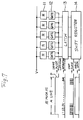
- Fig. 7 shows an electric arrangement of the thermal head 10 of the line type dye thermal printer which comprises line arranged heating resistors (Rs) 11 the number of which corresponds to the number of all the dots of an input data, gates 12 the number of which corresponds to that of the heating resistors (R), a latch circuit 13 and a shift register 14 serving as a data input portion.
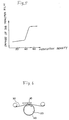
- a drive pulse (energizing instruction) P which is applied to the gate 12, has a pulse width (energizing time) corresponding to the number of modulation density modes of the input data and the pulse width is determined by a drive voltage V. That is, when the drive voltage V is determined, a graph as illustrated in Fig.
- a vertical axis represents density and a lateral axis represents the pulse width (energizing time). If the density is divided into 64, supposing that the maximum density is set to be, e.g. 2 in the optical density, the pulse width for realizing each of the modulation density mode 1 to mode 64 can be determined. When the modulation density are represented in 64 modes, the same input data should be latched 64 times in the latch circuit 13.
- the drive pulse P having the thus determined maximum pulse width pulse width for obtaining the maximum density
- the drive voltage V is applied to the heating resistors 11 for the period of the maximum pulse width so that the heating resistors 14 are heated at the maximum temperature.
- the transfer film 30 comprises a thermoplastic polyester resin which is generally employed as the transfer film, it has the softening temperature of 250 to 300°C. If the drive voltage V is increased to thereby supply the requisite quantity of heat within a short time so as to drive the printer at high speed, the maximum temperature exceeds the softening temperature whereby the heating area of the transfer film 30 is softened. Inasmuch as the transfer film 30 is stretched in its feeding direction, the softened heating area expands whereby distortion is generated at the boundary between the heating area and a non-heating area so that the transfer film is crumpled.
- the present invention has been made to solve the problem of the conventional dye thermal printer and to provide a system for driving a dye thermal printer capable of printing at high speed compared with the conventional dye thermal printer by preventing the transfer film from being crumpled.
- the system for driving the thermal head of the dye thermal printer according to the present invention for controlling energizing time of heating resistors by applying a drive pulse, to a gate connected to the corresponding heating resistor, the drive pulses each having a pulse width corresponding to a modulation density of an input data, every time the data is input thereto, characterized in that the drive pulse having the pulse width corresponding to the modulation density is applied to the gate until the modulation density reaches a given modulation density and repetition pulses are applied to the gate when the modulation density exceeds the given modulation density.
- a continuous drive pulse is applied to the gate within a given time and repetition pulses are applied to the gate after the given time elapsed.
- system of the third aspect of the invention comprising a temperature sensor in which a continuous drive pulse is applied to the gate until an output of the temperature sensor reaches a given value and repetition pulses are applied to the gate after the output of the temperature exceeds the given value.
- the continuous energization is switched to an ON/OFF (intermittent) energization when the energizing time of the heating resistors exceeds the given time at the given high order modulation density mode so that the heating resistors are repetitively heated and cooled, whereby the transfer film is prevented from rising in its temperature after the switching.
- a drive pulse to be applied to the gate 12 comprises a pulse P1 having a pulse width corresponding to the modulation density of the input data and a repetition pulse P2 wherein the pulse P1 is applied to the gate 12 when the modulation density is below the given density K and the repetition pulses P2 are given to the gate 12 when the modulation density is higher than the density K.
- the continuous pulses P1 or the repetition pulses P2 are applied to the gate 12 via an OR gate 15.
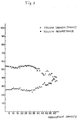
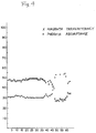
- Figs. 3 and 4 are graphs showing the relation between transmittance and the modulation density (represented by x) of the transfer film and the relation between the absorption factor and the modulation density (represented by ⁇ ) of the transfer film respectively tested for yellow and magenta.
- Fig 5 is a view prepared by the combination of Figs. 3 and 4 and showing the relation between the damage such as a crumple and the dot density modulation of the transfer film 30.
- the transmittance lowers at about the mode 40 and the transfer film 30 is crumpled as shown in Figs. 3 to 5. That is, when the temperature of the heating resistor reaches at the temperature where the modulation density at the mode 40 can be realized, the heated area of the transfer film 30 reaches to the softening temperature. The transmittance rises at about the density 50, which shows that the degree of sublimation is increased and the color fading in the film is enlarged.
- the modulation density mode is, e.g., 64
- the pulse P1 having the pulse width determined on the basis of the test as illustrated in Fig. 7 is given to the gate 12 until the mode 39 where the transfer film 30 is not softened while the repetition pulse P2 is applied to the gate 12 when the mode exceeds 40.
- the heating resistor 11 When the repetition pulses P2 are applied to the gate 12, the heating resistor 11 is ON for a given short time and is OFF for another given time, namely is repetitively ON/OFF whereby the thermal resistor is cooled when it is OFF.
- the temperature of the heating area of the transfer film 30 is suppressed under the softening temperature by appropriately setting the ON and OFF times as illustrated in Fig. 2, whereby the printing up to the mode 64 (maximum density) can be realized.
- the temperature of the film in the conventional dye thermal printer is illustrated in doted lines in Fig. 2.
- the continuous energization is switched to the ON/OFF energization when the energization time of the heating resistor exceeds the given time, it is possible to prevent the heating area of the transfer film 30 from being softened even if the drive voltage V is high so that the high printing can be performed compared with the conventional system accordingly.
- the switching between the continuous pulse P1 and the repetition pulses P2 is made based on the modulation density of the input data, it can be made based on an output value of a temperature sensor when provided in the dye thermal printer or based on an output value of a timer means when provided in the dye thermal printer.
- the continuous energization is switched to the ON/OFF energization when the energization time of the heating resistor exceeds the given time, it is possible to suppress the temperature rising of the transfer film. Even if the drive voltage is increased to thereby increase the amount of the heat generated in the heating resistor per unit time, the heating area of the transfer film can be prevented from being softened so that the restriction or the problem caused by the temperature characteristics of the transfer film is eliminated, whereby the high printing can be realized accordingly.
Landscapes
- Electronic Switches (AREA)
Applications Claiming Priority (2)
| Application Number | Priority Date | Filing Date | Title |
|---|---|---|---|
| JP121446/91 | 1991-05-27 | ||
| JP3121446A JPH04347665A (ja) | 1991-05-27 | 1991-05-27 | 昇華式プリンタのサーマルヘッド駆動方式 |
Publications (2)
| Publication Number | Publication Date |
|---|---|
| EP0516091A2 true EP0516091A2 (de) | 1992-12-02 |
| EP0516091A3 EP0516091A3 (en) | 1993-03-10 |
Family
ID=14811342
Family Applications (1)
| Application Number | Title | Priority Date | Filing Date |
|---|---|---|---|
| EP19920108963 Withdrawn EP0516091A3 (en) | 1991-05-27 | 1992-05-27 | System for driving thermal head of dye thermal printer |
Country Status (2)
| Country | Link |
|---|---|
| EP (1) | EP0516091A3 (de) |
| JP (1) | JPH04347665A (de) |
Family Cites Families (3)
| Publication number | Priority date | Publication date | Assignee | Title |
|---|---|---|---|---|
| US4675695A (en) * | 1985-12-13 | 1987-06-23 | Intermec Corporation | Method and apparatus for temperature control in thermal printers |
| JP2503589B2 (ja) * | 1988-05-24 | 1996-06-05 | 富士ゼロックス株式会社 | 画像記録装置 |
| US5025267A (en) * | 1988-09-23 | 1991-06-18 | Datacard Corporation | Thermal print head termperature control |
-
1991
- 1991-05-27 JP JP3121446A patent/JPH04347665A/ja active Pending
-
1992
- 1992-05-27 EP EP19920108963 patent/EP0516091A3/en not_active Withdrawn
Also Published As
| Publication number | Publication date |
|---|---|
| JPH04347665A (ja) | 1992-12-02 |
| EP0516091A3 (en) | 1993-03-10 |
Similar Documents
| Publication | Publication Date | Title |
|---|---|---|
| EP0244441B1 (de) | Vorrichtung und verfahren zur regelung eines wärmedruckers | |
| US3596055A (en) | Method and apparatus for producing displays utilizing an electronic display system | |
| US4560993A (en) | Thermal printing method and thermal printer | |
| EP0516091A2 (de) | Steuerungsverfahren eines Thermo-Druckkopfes eines Thermo-Farbdruckers | |
| US4800399A (en) | Pulsed constant current source for continuous tone resistive ribbon printers | |
| JPH0659739B2 (ja) | 熱転写型印刷装置 | |
| US7319473B2 (en) | Thermal recording system and method | |
| JP3021268B2 (ja) | サーマルプリンタ | |
| JPS61286170A (ja) | サ−マルヘツド駆動回路 | |
| JPH05201054A (ja) | サーマルプリンターのためのプリンターヘッド変調方法および装置 | |
| JP3251989B2 (ja) | カラー感熱プリンタ | |
| JP2709057B2 (ja) | サーマル印刷制御回路 | |
| JP2518640Y2 (ja) | マルチ印字装置 | |
| JPH01241463A (ja) | 熱ヘッド駆動回路 | |
| JP3408551B2 (ja) | サーマルヘッド制御装置 | |
| JPH05147252A (ja) | 印字濃度自動調整回路 | |
| JP2514566Y2 (ja) | サーマルプリンタ | |
| JP2824362B2 (ja) | サーマルプリンタの熱履歴補正方法 | |
| JPH08238789A (ja) | カラー感熱記録装置 | |
| JPS60135272A (ja) | 感熱記録装置 | |
| JPH0664212A (ja) | サーマルヘッド駆動装置 | |
| JPH01186340A (ja) | 昇華型熱転写プリンタの駆動方法 | |
| JPS62104775A (ja) | サ−マルプリンタのサ−マルヘツド焼損防止回路 | |
| JPH08230218A (ja) | カラー感熱記録装置 | |
| JP2000280510A (ja) | サーマルプリンタの濃度むら補正方法及びサーマルプリンタ |
Legal Events
| Date | Code | Title | Description |
|---|---|---|---|
| PUAI | Public reference made under article 153(3) epc to a published international application that has entered the european phase |
Free format text: ORIGINAL CODE: 0009012 |
|
| AK | Designated contracting states |
Kind code of ref document: A2 Designated state(s): DE FR GB |
|
| PUAL | Search report despatched |
Free format text: ORIGINAL CODE: 0009013 |
|
| AK | Designated contracting states |
Kind code of ref document: A3 Designated state(s): DE FR GB |
|
| 17P | Request for examination filed |
Effective date: 19930825 |
|
| 17Q | First examination report despatched |
Effective date: 19940712 |
|
| STAA | Information on the status of an ep patent application or granted ep patent |
Free format text: STATUS: THE APPLICATION IS DEEMED TO BE WITHDRAWN |
|
| 18D | Application deemed to be withdrawn |
Effective date: 19941123 |