EP0516422A2 - Vakuummeter - Google Patents
Vakuummeter Download PDFInfo
- Publication number
- EP0516422A2 EP0516422A2 EP92304850A EP92304850A EP0516422A2 EP 0516422 A2 EP0516422 A2 EP 0516422A2 EP 92304850 A EP92304850 A EP 92304850A EP 92304850 A EP92304850 A EP 92304850A EP 0516422 A2 EP0516422 A2 EP 0516422A2
- Authority
- EP
- European Patent Office
- Prior art keywords
- anode
- cathode sleeve
- guard ring
- vacuum
- cathode
- Prior art date
- Legal status (The legal status is an assumption and is not a legal conclusion. Google has not performed a legal analysis and makes no representation as to the accuracy of the status listed.)
- Withdrawn
Links
- 238000002955 isolation Methods 0.000 claims abstract description 3
- 239000011810 insulating material Substances 0.000 claims description 3
- 239000007787 solid Substances 0.000 claims description 3
- 239000002184 metal Substances 0.000 claims description 2
- 239000012777 electrically insulating material Substances 0.000 claims 1
- 150000002500 ions Chemical class 0.000 description 7
- 229910001220 stainless steel Inorganic materials 0.000 description 3
- 239000010935 stainless steel Substances 0.000 description 3
- 230000005684 electric field Effects 0.000 description 2
- 229920002449 FKM Polymers 0.000 description 1
- 230000006835 compression Effects 0.000 description 1
- 238000007906 compression Methods 0.000 description 1
- 238000010586 diagram Methods 0.000 description 1
- 230000000694 effects Effects 0.000 description 1
- 238000010292 electrical insulation Methods 0.000 description 1
- 239000011521 glass Substances 0.000 description 1
- 239000000463 material Substances 0.000 description 1
Images
Classifications
-
- G—PHYSICS
- G01—MEASURING; TESTING
- G01L—MEASURING FORCE, STRESS, TORQUE, WORK, MECHANICAL POWER, MECHANICAL EFFICIENCY, OR FLUID PRESSURE
- G01L21/00—Vacuum gauges
- G01L21/30—Vacuum gauges by making use of ionisation effects
- G01L21/34—Vacuum gauges by making use of ionisation effects using electric discharge tubes with cold cathodes
Definitions
- This invention relate to vacuum gauges and, more particularly, to improvements to cold cathode ionisation vacuum gauges, especially those of the inverted magnetron type.
- Cold cathode ionisation gauges for measuring vacuum are well known. They generally comprise an anode and one (or more) cathodes with a large potential difference between the anode and the cathode(s) and a substantial magnetic field applied by a permanent magnet in the area between the electrodes. In these gauges, the anode and cathode are held in a predetermined configuration relative to each other by means of a vacuum feedthrough which isolates the electrodes within the gauge from the atmosphere outside.
- the cathode commonly has associated with it means to define a region within it in which the ion collection, and hence ion discharge current to the external circuit takes place and is measured. This is generally achieved by arranging for the magnetic and electric fields to be concentrated in that region.
- guard ring In such inverted magnetron gauges, it is possible for a small current to flow directly from the anode to the cathode via the internal surfaces of the gauge and it is known that the presence of a so-called “guard ring” can collect this current and thereby prevent it being detected by the gauge itself. To perform this function, the guard ring is electrically isolated from the cathode and normally held at a small positive potential relative to the cathode.
- the present invention is concerned with the provision of an improved guard-ring arrangement in gauges of this type.
- a vacuum gauge of the ionisation type having a gauge head which comprises:
- the cathode sleeve is cylindrical in shape and can usefully be made from stainless steel.
- the anode will generally be a solid rod of metal, for example stainless steel also.
- the guard ring can preferably also be fixed within the cathode sleeve by any convenient means.
- the guard ring must be isolated electrically from the cathode, preferably by inserting therebetween an insulating material.
- the anode is preferably positioned in the gauge head such that it lies substantially on the main axis of the guard ring. It must also be isolated electrically from the guard ring and this is preferably effected by placing an insulating material about the anode and within the ring aperture.
- the positioning means for the cathode sleeve, guard ring and anode can thus all be arranged in a substantially radial configuration within the cathode sleeve.
- the vacuum feedthrough comprises (positioned within one end of the cathode sleeve) a concentric arrangement comprising the guard ring and the anode with the anode held within the guard ring by means of an electrically insulating seal material.
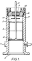
- Figure 1 shows a sectional view through a gauge head of the invention.
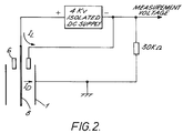
- Figure 2 shows a circuit diagram for the gauge head of Figure 1.
- Figure 1 shows a gauge head which comprises a substantially cylindrical cathode sleeve 1 having an inlet 2 at one end for communication with the vacuum to be measured.
- a drum-shaped component 3 having an external diameter substantially the same of the internal diameter of the cathode sleeve 1; the component 3 is held substantially centrally along the length of the sleeve 1.
- the component 3 has two circular end portions 4,5, both with circular central apertures.
- the collector 3 is electrically connected to the cathode sleeve 1 and therefore forms an ion collecting region.
- a guard ring 6 Also positioned within the cathode sleeve 1 is a guard ring 6; it is positioned on a radiussed ledge 7 in the cathode sleeve and electrically insulated therefrom by a compressed '0' ring made of VITON (Trade Mark) A, leaving a 1mm air gap between these components.
- anode 8 Positioned centrally within the cathode sleeve 1 and passing through the upper (as shown) circular aperture of collector end portion 5 and through the aperture of the guard ring 6 is an anode 8 in the form of a solid rod made from stainless steel.
- the anode 8 is held in position by means of a fused glass compression seal 9 placed within the aperture of the guard ring 6.
- the anode is also held in position by use of a plastic collar 10 which effects further electrical insulation between the guard ring 6 and the cathode sleeve 1.
- a circular disc component 11 is positioned about the anode 8 between the guard ring 6 and the collector 3. It is in electrical contact with the anode 8 and acts to repel any ions which might attempt to escape from the collecting region defined by component 3.
- the positioning means and the guard ring are arranged in a substantially concentric configuration within the cathode sleeve 1.
- the positioning means for the gauge head components described above also performs the function of ensuring that this end of the gauge head is firmly sealed against vacuum at the point of entry of the anode into the head and in the general vicinity of the guard ring.
- the anode 8 is held at a potential difference of, for example, 4 Kv relative to the cathode sleeve 1 (and to the component 3).
- the gauge operates by measuring the current flowing between the anode and the cathode I D when a "cold cathode discharge" is formed within region defined by the collector 3 by the ionisation of gas molecules by electrons emitted by the cathode.
Landscapes
- Physics & Mathematics (AREA)
- General Physics & Mathematics (AREA)
- Measuring Fluid Pressure (AREA)
Applications Claiming Priority (2)
| Application Number | Priority Date | Filing Date | Title |
|---|---|---|---|
| GB919111747A GB9111747D0 (en) | 1991-05-31 | 1991-05-31 | Improvements relating to vacuum pumps |
| GB9111747 | 1991-05-31 |
Publications (2)
| Publication Number | Publication Date |
|---|---|
| EP0516422A2 true EP0516422A2 (de) | 1992-12-02 |
| EP0516422A3 EP0516422A3 (en) | 1993-01-20 |
Family
ID=10695887
Family Applications (1)
| Application Number | Title | Priority Date | Filing Date |
|---|---|---|---|
| EP19920304850 Withdrawn EP0516422A3 (en) | 1991-05-31 | 1992-05-28 | Improvements relating to vacuum gauges |
Country Status (4)
| Country | Link |
|---|---|
| US (1) | US5317270A (de) |
| EP (1) | EP0516422A3 (de) |
| JP (1) | JPH05264389A (de) |
| GB (1) | GB9111747D0 (de) |
Cited By (5)
| Publication number | Priority date | Publication date | Assignee | Title |
|---|---|---|---|---|
| WO1998048445A1 (de) * | 1997-04-24 | 1998-10-29 | Leybold Vakuum Gmbh | Penning-vakuummeter |
| EP1698878A1 (de) * | 2005-03-04 | 2006-09-06 | Inficon GmbH | Elektrodenanordnung und Druckmessvorrichtung |
| US7189111B2 (en) | 2005-05-19 | 2007-03-13 | Bae Industries, Inc. | Stand-off bracket for securing a wire harness connector assembly to DC electric motor and associated method |
| WO2009063233A2 (en) | 2007-11-12 | 2009-05-22 | Edwards Limited | Ionisation vacuum gauges and gauge heads |
| EP3564983A1 (de) * | 2015-09-23 | 2019-11-06 | Inficon AG | Ionisations-vakuummesszelle |
Families Citing this family (8)
| Publication number | Priority date | Publication date | Assignee | Title |
|---|---|---|---|---|
| JP5000386B2 (ja) * | 2007-06-08 | 2012-08-15 | 株式会社アルバック | 冷陰極電離真空計 |
| RU2497089C2 (ru) * | 2012-02-08 | 2013-10-27 | Открытое акционерное общество "Научно-производственное объединение измерительной техники" | Ионизационный вакуумметр |
| CH707685A1 (de) * | 2013-03-06 | 2014-09-15 | Inficon Gmbh | Ionisations-Vakuummesszelle mit Abschirmvorrichtung. |
| JP6131113B2 (ja) * | 2013-06-13 | 2017-05-17 | キヤノンアネルバ株式会社 | 冷陰極電離真空計及び内壁保護部材 |
| US9671302B2 (en) * | 2013-09-30 | 2017-06-06 | Mks Instruments, Inc. | Cold cathode ionization vacuum gauge |
| TWI795918B (zh) | 2015-01-15 | 2023-03-11 | 美商Mks儀器公司 | 製造測量裝置之方法 |
| US10969290B2 (en) | 2016-12-13 | 2021-04-06 | Mks Instruments, Inc. | Anode electrode shield for inverted magnetron cold cathode ionization gauge |
| RU2682067C2 (ru) * | 2017-03-29 | 2019-03-14 | Федеральное государственное бюджетное образовательное учреждение высшего образования "Юго-Западный государственный университет "(ЮЗГУ) | Высокочувствительный ионизационный вакуумметрический преобразователь |
Family Cites Families (9)
| Publication number | Priority date | Publication date | Assignee | Title |
|---|---|---|---|---|
| US2137198A (en) * | 1925-03-05 | 1938-11-15 | Raytheon Mfg Co | Electric device |
| US3244990A (en) * | 1963-02-26 | 1966-04-05 | Wisconsin Alumni Res Found | Electron vacuum tube employing orbiting electrons |
| US3387175A (en) * | 1965-03-05 | 1968-06-04 | Varian Associates | Vacuum gauge having separate electron collecting and electron accelerating electrodes |
| CH425007A (de) * | 1965-07-15 | 1966-11-30 | Bbc Brown Boveri & Cie | Quecksilberdampf-Stromrichter mit in Durchführungsisolator untergebrachten Anodenzuleitungen |
| CH431131A (de) * | 1966-02-02 | 1967-02-28 | Balzers Patent Beteilig Ag | Kaltkathodenionisationsmanometer |
| CH448559A (de) * | 1967-01-05 | 1967-12-15 | Balzers Patent Beteilig Ag | Kaltkathodenionisationsmanometerröhre |
| US3505554A (en) * | 1968-01-05 | 1970-04-07 | Sergei Arkadievich Vekshinsky | Ionization pressure gauge |
| DE3642670A1 (de) * | 1986-12-13 | 1988-06-23 | Leybold Ag | Penning-ionisationsvakuummeter |
| US4967157A (en) * | 1988-08-29 | 1990-10-30 | Mks Instruments, Inc. | Method and circuit for extending the range of a cold cathode discharge vacuum gauge |
-
1991
- 1991-05-31 GB GB919111747A patent/GB9111747D0/en active Pending
-
1992
- 1992-05-25 JP JP4131253A patent/JPH05264389A/ja active Pending
- 1992-05-28 US US07/890,058 patent/US5317270A/en not_active Expired - Fee Related
- 1992-05-28 EP EP19920304850 patent/EP0516422A3/en not_active Withdrawn
Cited By (11)
| Publication number | Priority date | Publication date | Assignee | Title |
|---|---|---|---|---|
| WO1998048445A1 (de) * | 1997-04-24 | 1998-10-29 | Leybold Vakuum Gmbh | Penning-vakuummeter |
| US6285192B1 (en) | 1997-04-24 | 2001-09-04 | Leybold Vakuum Gmbh | Penning vacuum meter |
| EP1698878A1 (de) * | 2005-03-04 | 2006-09-06 | Inficon GmbH | Elektrodenanordnung und Druckmessvorrichtung |
| WO2006094687A1 (en) * | 2005-03-04 | 2006-09-14 | Inficon Gmbh | Vacuum measuring gauge |
| US7352187B2 (en) | 2005-03-04 | 2008-04-01 | Inficon Gmbh | Vacuum measuring gauge |
| CN101133308B (zh) * | 2005-03-04 | 2011-08-03 | 英飞康有限责任公司 | 真空测量仪 |
| TWI395935B (zh) * | 2005-03-04 | 2013-05-11 | Inficon Gmbh | 真空量測計 |
| US7189111B2 (en) | 2005-05-19 | 2007-03-13 | Bae Industries, Inc. | Stand-off bracket for securing a wire harness connector assembly to DC electric motor and associated method |
| WO2009063233A2 (en) | 2007-11-12 | 2009-05-22 | Edwards Limited | Ionisation vacuum gauges and gauge heads |
| EP3564983A1 (de) * | 2015-09-23 | 2019-11-06 | Inficon AG | Ionisations-vakuummesszelle |
| US11164731B2 (en) | 2015-09-23 | 2021-11-02 | Inficon ag | Ionization vacuum measuring cell |
Also Published As
| Publication number | Publication date |
|---|---|
| EP0516422A3 (en) | 1993-01-20 |
| GB9111747D0 (en) | 1991-07-24 |
| US5317270A (en) | 1994-05-31 |
| JPH05264389A (ja) | 1993-10-12 |
Similar Documents
| Publication | Publication Date | Title |
|---|---|---|
| US5317270A (en) | Cold cathode ionization vacuum gauge with guard ring | |
| US2454564A (en) | Ionization-type vacuum gauge | |
| US4403124A (en) | Vacuum circuit interrupter with insulated vacuum monitor resistor | |
| EP1039285B1 (de) | Kaltkathoden-Vakuummeter | |
| US4672323A (en) | Device for measuring the internal pressure of an operationally built built-in vacuum switch | |
| US2884550A (en) | Ionization gauges and method of operation thereof | |
| US3263162A (en) | Apparatus and method for measuring the pressure inside a vacuum circuit interrupter | |
| US2864998A (en) | Pressure measuring arrangement for a vacuum circuit interrupter | |
| JPS63151835A (ja) | ペニング電離真空計 | |
| EP0056722A2 (de) | Vakuumschalter mit eingebauter Überwachungsvorrichtung | |
| US3070283A (en) | Vacuum pump | |
| US3387175A (en) | Vacuum gauge having separate electron collecting and electron accelerating electrodes | |
| GB2256310A (en) | A vacuum gauge | |
| EP0717433B1 (de) | Vorrichtung zur Verringerung der Kontamination einer Ionenquelle zur Verwendung in einem Massenspektrometer zur Lecksuche | |
| US3324729A (en) | Method and apparatus for detecting leaks | |
| US2592242A (en) | Electron gun and mounting therefor | |
| EP3249677B1 (de) | Miniaturionenpumpe | |
| US3449660A (en) | Orbitron electronic vacuum gauge having second anode for collecting scattered electrons | |
| US3495127A (en) | Ultra-high vacuum magnetron ionization gauge with ion-collector shield | |
| US3496399A (en) | Ion gauge with collector plates anf anodes perpendicular to each other | |
| US3320455A (en) | Ionization vacuum gauge having x-ray shielding means | |
| US4247782A (en) | X-ray tube unit | |
| WO2019082893A1 (ja) | ガス分析器 | |
| US3080104A (en) | Ionic pump | |
| KR20010100913A (ko) | 산란 타겟 보지용 기구 및 전자 스핀 분석기 |
Legal Events
| Date | Code | Title | Description |
|---|---|---|---|
| PUAI | Public reference made under article 153(3) epc to a published international application that has entered the european phase |
Free format text: ORIGINAL CODE: 0009012 |
|
| AK | Designated contracting states |
Kind code of ref document: A2 Designated state(s): CH DE FR GB LI |
|
| PUAL | Search report despatched |
Free format text: ORIGINAL CODE: 0009013 |
|
| AK | Designated contracting states |
Kind code of ref document: A3 Designated state(s): CH DE FR GB LI |
|
| 17P | Request for examination filed |
Effective date: 19930719 |
|
| 17Q | First examination report despatched |
Effective date: 19941219 |
|
| STAA | Information on the status of an ep patent application or granted ep patent |
Free format text: STATUS: THE APPLICATION IS DEEMED TO BE WITHDRAWN |
|
| 18D | Application deemed to be withdrawn |
Effective date: 19960130 |