EP0516539A1 - Vorrichtung zum Verschieben eines beweglichen Teiles von einer erste Stelle zu einer zweiten Stelle und zum Halten des Teiles in jeder dieser Stellen - Google Patents
Vorrichtung zum Verschieben eines beweglichen Teiles von einer erste Stelle zu einer zweiten Stelle und zum Halten des Teiles in jeder dieser Stellen Download PDFInfo
- Publication number
- EP0516539A1 EP0516539A1 EP92401455A EP92401455A EP0516539A1 EP 0516539 A1 EP0516539 A1 EP 0516539A1 EP 92401455 A EP92401455 A EP 92401455A EP 92401455 A EP92401455 A EP 92401455A EP 0516539 A1 EP0516539 A1 EP 0516539A1
- Authority
- EP
- European Patent Office
- Prior art keywords
- point
- pivot
- situation
- moving part
- moving
- Prior art date
- Legal status (The legal status is an assumption and is not a legal conclusion. Google has not performed a legal analysis and makes no representation as to the accuracy of the status listed.)
- Withdrawn
Links
- 239000002131 composite material Substances 0.000 claims abstract description 6
- 230000006641 stabilisation Effects 0.000 claims description 4
- 238000011105 stabilization Methods 0.000 claims description 4
- 239000004593 Epoxy Substances 0.000 claims description 2
- 239000000835 fiber Substances 0.000 claims description 2
- 230000003100 immobilizing effect Effects 0.000 claims description 2
- 230000000750 progressive effect Effects 0.000 claims description 2
- 230000002427 irreversible effect Effects 0.000 claims 3
- 229920000728 polyester Polymers 0.000 claims 1
- 238000009434 installation Methods 0.000 abstract description 3
- 230000001960 triggered effect Effects 0.000 abstract 1
- 230000000087 stabilizing effect Effects 0.000 description 3
- 101001017827 Mus musculus Leucine-rich repeat flightless-interacting protein 1 Proteins 0.000 description 2
- 238000010586 diagram Methods 0.000 description 2
- 238000004146 energy storage Methods 0.000 description 2
- 229910000831 Steel Inorganic materials 0.000 description 1
- 238000009825 accumulation Methods 0.000 description 1
- 238000013016 damping Methods 0.000 description 1
- 238000006073 displacement reaction Methods 0.000 description 1
- 239000011521 glass Substances 0.000 description 1
- 239000002184 metal Substances 0.000 description 1
- 238000000034 method Methods 0.000 description 1
- 230000003287 optical effect Effects 0.000 description 1
- 230000002028 premature Effects 0.000 description 1
- 230000002040 relaxant effect Effects 0.000 description 1
- 230000002441 reversible effect Effects 0.000 description 1
- 230000035939 shock Effects 0.000 description 1
- 239000003381 stabilizer Substances 0.000 description 1
- 239000010959 steel Substances 0.000 description 1
Images

Classifications
-
- B—PERFORMING OPERATIONS; TRANSPORTING
- B65—CONVEYING; PACKING; STORING; HANDLING THIN OR FILAMENTARY MATERIAL
- B65G—TRANSPORT OR STORAGE DEVICES, e.g. CONVEYORS FOR LOADING OR TIPPING, SHOP CONVEYOR SYSTEMS OR PNEUMATIC TUBE CONVEYORS
- B65G47/00—Article or material-handling devices associated with conveyors; Methods employing such devices
- B65G47/52—Devices for transferring articles or materials between conveyors i.e. discharging or feeding devices
- B65G47/64—Switching conveyors
- B65G47/644—Switching conveyors by a pivoting displacement of the switching conveyor
- B65G47/648—Switching conveyors by a pivoting displacement of the switching conveyor about a vertical axis
-
- B—PERFORMING OPERATIONS; TRANSPORTING
- B07—SEPARATING SOLIDS FROM SOLIDS; SORTING
- B07C—POSTAL SORTING; SORTING INDIVIDUAL ARTICLES, OR BULK MATERIAL FIT TO BE SORTED PIECE-MEAL, e.g. BY PICKING
- B07C3/00—Sorting according to destination
- B07C3/02—Apparatus characterised by the means used for distribution
- B07C3/06—Linear sorting machines in which articles are removed from a stream at selected points
- B07C3/065—Linear sorting machines in which articles are removed from a stream at selected points construction of switches therefor
-
- B—PERFORMING OPERATIONS; TRANSPORTING
- B65—CONVEYING; PACKING; STORING; HANDLING THIN OR FILAMENTARY MATERIAL
- B65H—HANDLING THIN OR FILAMENTARY MATERIAL, e.g. SHEETS, WEBS, CABLES
- B65H29/00—Delivering or advancing articles from machines; Advancing articles to or into piles
- B65H29/58—Article switches or diverters
-
- B—PERFORMING OPERATIONS; TRANSPORTING
- B65—CONVEYING; PACKING; STORING; HANDLING THIN OR FILAMENTARY MATERIAL
- B65H—HANDLING THIN OR FILAMENTARY MATERIAL, e.g. SHEETS, WEBS, CABLES
- B65H2301/00—Handling processes for sheets or webs
- B65H2301/30—Orientation, displacement, position of the handled material
- B65H2301/32—Orientation of handled material
- B65H2301/321—Standing on edge
-
- B—PERFORMING OPERATIONS; TRANSPORTING
- B65—CONVEYING; PACKING; STORING; HANDLING THIN OR FILAMENTARY MATERIAL
- B65H—HANDLING THIN OR FILAMENTARY MATERIAL, e.g. SHEETS, WEBS, CABLES
- B65H2404/00—Parts for transporting or guiding the handled material
- B65H2404/60—Other elements in face contact with handled material
- B65H2404/63—Oscillating, pivoting around an axis parallel to face of material, e.g. diverting means
- B65H2404/632—Wedge member
-
- B—PERFORMING OPERATIONS; TRANSPORTING
- B65—CONVEYING; PACKING; STORING; HANDLING THIN OR FILAMENTARY MATERIAL
- B65H—HANDLING THIN OR FILAMENTARY MATERIAL, e.g. SHEETS, WEBS, CABLES
- B65H2555/00—Actuating means
- B65H2555/20—Actuating means angular
- B65H2555/24—Servomotors
-
- B—PERFORMING OPERATIONS; TRANSPORTING
- B65—CONVEYING; PACKING; STORING; HANDLING THIN OR FILAMENTARY MATERIAL
- B65H—HANDLING THIN OR FILAMENTARY MATERIAL, e.g. SHEETS, WEBS, CABLES
- B65H2701/00—Handled material; Storage means
- B65H2701/10—Handled articles or webs
- B65H2701/19—Specific article or web
- B65H2701/1916—Envelopes and articles of mail
Definitions
- the present invention relates to a device for moving a moving part between a first and a second position, and maintaining it in each of these positions, the movement being as rapid as possible.
- a postal sorting installation includes means for circulating letters from a single point of origin towards a variable number of boxes, each corresponding to a defined destination. A number of points allow the letters to be routed in the desired direction.
- These switches normally include a movable flap, which must be able to be held in one or the other of two fixed positions, and pass from one to the other of these positions, see for example FR-A-2,196,641 . It is understood that the speed at which the movable flap passes from one position to another conditions the performance of the entire system. There is therefore a need for a device allowing rapid passage from one position to the other of the switch flap, the latter being held securely in each of the two positions, so as to surely switch the letters in the right direction.
- switches there are a large number of types of switches in this field, and even in switches for domestic use, devices are encountered in which, for example, a spring is compressed during an approach stroke, the energy accumulated during the approach run then being used to quickly separate the electrical contacts from each other, see for example GB-A-1,578,274.
- the invention provides a device for moving a moving part between a first and a second position and maintaining it in each of these positions, this device acting by relaxation of an elastic means which is in a first situation when the moving part is in the first position, and in a second situation when the moving part is in the second position, and which passes through a first point of maximum stress when it is moved from the first situation to the second situation, and by a second point of maximum stress when it is moved from the second situation to the first, the trigger which moves the moving part from one position to the other occurring almost immediately after the elastic means has exceeded the point of maximum stress , the device further comprising actuating means for moving said elastic means between the first and second situations, this device having the particularity that said actuating means are capable of immobilizing the elastic means in a durable manner very shortly before the point of maximum stress, and causing it to pass this point to trigger relaxation at the desired moment.
- the first and second situations can be situations of stable equilibrium, i.e. situations to which the system tends to return if it has been set aside by a small amount.
- the first and second points of maximum stress are situations of unstable equilibrium, from which the system tends to move away if it has been slightly moved away from it.
- arming the action which brings the system from the first, or the second, situation to the vicinity of the first, or respectively of the second, point of maximum stress, with a relatively large energy input and during a relatively long time.
- One calls “relaxation” the action which makes exceed with the system the first or the second point of maximum stress to go until respectively the second or the first situation.
- Relaxation requires a low external energy supply, most of the necessary energy having been accumulated in the elastic means during arming.
- the relaxation time can be short, and the time of the beginning of the relaxation must be determined with great precision.
- the elastic means comprises a spring with variable section and constant inertia, made of composite material, as described in patent EP-A-0093707.
- a spring indeed has interesting internal damping properties.
- This spring is described below as “leaf spring”. It can also consist of a metal blade also designated by “leaf spring”.
- the leaf spring is deformed into an S shape in the vicinity of each point of maximum stress.
- the leaf spring comprises a main part, which is fixed by one of its ends to the moving part and the other end of which is capable of pivoting about a fixed axis, and a stabilization part, one end of which is integral with the main part only in the vicinity of said fixed axis, and the other end of which bears on a fixed point, this stabilization part having, between its two ends, an extension of approximately half that of the main part.
- the elastic means comprises an elastic piece of composite material.
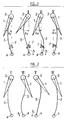
- FIGS. 1 and 2 show a movable part 1, mounted, without the possibility of rotation, on a pivot 2.
- a spring leaf 3 is fixed, also without the possibility of rotation, on the pivot 2.
- the pivot 2, itself, can rotate freely around its axis.
- the opposite end of the spring leaf 3 is mounted, without the possibility of rotation, on a second pivot 4, which drive means can rotate in a direction, indicated by the arrow 5, in the case of FIG. 1 , and in the opposite direction, arrow 6, in the case of FIG. 2.
- the leaf spring 3 is of a length slightly greater than that which separates the axes of the pivots 2 and 4.
- the median plane of the part 1 is shown as tangent to the leaf 3 where it joined pivot 2.
- the angles made by the tangent to the blade 3 with the straight line 1 which joins the axes of the pivots are designated by A I , A II etc. for the angles whose apex is on the axis of pivot 2, and by B I , B II , etc., for the angles whose apex is on the axis of the pivot 4.
- FIG. 2 shows the succession of steps IV, V, VI, I which corresponds to a rotation of the pivot 4 according to arrow 6, that is to say in the opposite direction to that which is represented in FIG. 1.
- the initial position in this case, is position IV
- final position is position I.
- the intermediate positions V and VI are different from positions III and II respectively.
- Figures 1 and 2 are deduced from each other by symmetry in a mirror.
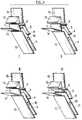
- FIG. 3 shows the assembly of a switching device according to the invention, in successive states corresponding to positions I, II, III, IV of FIG. 1.
- the route for routing the letters L is shown diagrammatically by two parallel plates 10, 11, and the starting paths of the letters are represented by the interval between a block 13 of roughly triangular section, and of plates 14, 15, each parallel to one of the faces of the block 13.
- the two faces assets of the block 13 converge on the axis of the pivot 2, integral with the switching part 1 and one end of the spring 3.
- the other end of the spring 3 is carried by the pivot 4.
- the arrow 16 symbolizes the direction of letters. It is easy to understand, on reading these figures, that in positions I, II and III, the letters are pointed to pass between the block 13 and the plate 15, while in position IV, the part switch 1 has tilted, so that the letters are sent between the plate 14 and the block 13.
- FIG. 4 is similar to FIG. 3, the only difference relating to the structure of the spring 3.
- This comprises a main part 20, which, as previously described, extends between the pivot 2 and the pivot 4, and a stabilizing part 21, parallel to the main part 20, but of substantially half length, and which extends between the pivot 4 and an auxiliary pivot 22 situated in the plane defined by the axes of the pivots 2 and 4.
- the stabilizing part 21 is integral with the pivot 4, like the part 20, so that the rotation of the pivot 4 simultaneously causes the end of the parts 20 and 21 to pivot.
- the length of the part 21 is greater than the distance between the pivots 4 and 22, in the same way that the length of the part 20 is greater than the distance between the pivots 4 and 2.
- the excess length of the part 21 is, in proportion, greater than the excess length of the part 20 , so that, as we can see, in the p Position III, part 20 has already taken an S shape, while part 21 still has a unique curvature. This results in a stabilizing effect, a greater force is necessary at the time of triggering, to pass from position III to position IV.
- the leaf spring 3 is a piece of composite material, of the glass / epoxy type, with unidirectional long fibers not crossed, which has a high breaking strength and a very good resistance to fatigue. Such blades have a specific energy storage capacity 4 to 5 times greater than that of steel.
- the leaf spring in one example, has progressive inertia: its height increases from 50 to 10 mm, while its thickness varies from 0.8 to 4 mm, for a length of 180 mm.
- the leaf spring is anchored by one of its ends in a slot in pivot 2, and by the other end in a slot in pivot 4.
- two leaf springs (3A, 3B) are used anchored in the pivots 2 and 4 with a slight angular offset, which improves the stability in the stopping phase.
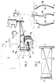
- a two-way stepping motor 32 has a threaded shaft 33, which penetrates into a female threaded part 34, forming a nut, connected without possible rotation to a plate 35 held in a yoke 36 integral with the pivot 4. It will be appreciated that the rotation of the motor causes an axial displacement of the part 34, which causes the rotation of the pivot 4 on its axis, and causes the spring 3 to pass from a first situation, of stable equilibrium, to a second situation, also of stable equilibrium, according to the two-way arrow 37, passing through the arming, stopping and detent phases.
- An optical sensor 38 detects the front edge of an incoming letter L, and controls, by means not shown, the rotation of the motor for the start of the expansion phase, if a change of position of the flap 1 is necessary.
- the device of the invention can also operate according to the more conventional mode, where the trigger immediately follows the arming, the arrival of a letter, or other determining object, the beginning of the succession of these two phases.
Landscapes
- Engineering & Computer Science (AREA)
- Mechanical Engineering (AREA)
- Springs (AREA)
- Toys (AREA)
Applications Claiming Priority (2)
| Application Number | Priority Date | Filing Date | Title |
|---|---|---|---|
| FR9106502 | 1991-05-30 | ||
| FR9106502A FR2677003B1 (fr) | 1991-05-30 | 1991-05-30 | Dispositif pour deplacer une piece mobile entre une premiere et une seconde positions et la maintenir dans chacune de ces positions. |
Publications (1)
| Publication Number | Publication Date |
|---|---|
| EP0516539A1 true EP0516539A1 (de) | 1992-12-02 |
Family
ID=9413269
Family Applications (1)
| Application Number | Title | Priority Date | Filing Date |
|---|---|---|---|
| EP92401455A Withdrawn EP0516539A1 (de) | 1991-05-30 | 1992-05-27 | Vorrichtung zum Verschieben eines beweglichen Teiles von einer erste Stelle zu einer zweiten Stelle und zum Halten des Teiles in jeder dieser Stellen |
Country Status (2)
| Country | Link |
|---|---|
| EP (1) | EP0516539A1 (de) |
| FR (1) | FR2677003B1 (de) |
Cited By (3)
| Publication number | Priority date | Publication date | Assignee | Title |
|---|---|---|---|---|
| ES2164501A1 (es) * | 1998-06-24 | 2002-02-16 | Ct De Estudios Y Desarrollos I | Maquina clasificadora automatica de sobres y pequeña paqueteria. |
| EP2017208A3 (de) * | 2007-07-18 | 2009-08-05 | Seiko Epson Corporation | Medientrennmechanismus für eine Blattmedienverarbeitungsvorrichtung und Medienverarbeitungsvorrichtung |
| CN111867951A (zh) * | 2017-12-22 | 2020-10-30 | 温科尼克斯多夫国际有限公司 | 用于处理有价票券用的装置的转辙组件 |
Citations (3)
| Publication number | Priority date | Publication date | Assignee | Title |
|---|---|---|---|---|
| FR2196641A5 (de) * | 1972-08-19 | 1974-03-15 | Kleindienst & Co | |
| GB1578274A (en) * | 1978-04-04 | 1980-11-05 | Standard Telephones Cables Ltd | Electrical contact mechanism |
| US4721298A (en) * | 1986-08-29 | 1988-01-26 | Light Signatures, Inc. | Bi-stable paper separator |
-
1991
- 1991-05-30 FR FR9106502A patent/FR2677003B1/fr not_active Expired - Lifetime
-
1992
- 1992-05-27 EP EP92401455A patent/EP0516539A1/de not_active Withdrawn
Patent Citations (3)
| Publication number | Priority date | Publication date | Assignee | Title |
|---|---|---|---|---|
| FR2196641A5 (de) * | 1972-08-19 | 1974-03-15 | Kleindienst & Co | |
| GB1578274A (en) * | 1978-04-04 | 1980-11-05 | Standard Telephones Cables Ltd | Electrical contact mechanism |
| US4721298A (en) * | 1986-08-29 | 1988-01-26 | Light Signatures, Inc. | Bi-stable paper separator |
Cited By (5)
| Publication number | Priority date | Publication date | Assignee | Title |
|---|---|---|---|---|
| ES2164501A1 (es) * | 1998-06-24 | 2002-02-16 | Ct De Estudios Y Desarrollos I | Maquina clasificadora automatica de sobres y pequeña paqueteria. |
| EP2017208A3 (de) * | 2007-07-18 | 2009-08-05 | Seiko Epson Corporation | Medientrennmechanismus für eine Blattmedienverarbeitungsvorrichtung und Medienverarbeitungsvorrichtung |
| US7988151B2 (en) | 2007-07-18 | 2011-08-02 | Seiko Epson Corporation | Media diversion mechanism for a sheet media processing device, and a media processing device |
| CN111867951A (zh) * | 2017-12-22 | 2020-10-30 | 温科尼克斯多夫国际有限公司 | 用于处理有价票券用的装置的转辙组件 |
| CN111867951B (zh) * | 2017-12-22 | 2023-06-20 | 温科尼克斯多夫国际有限公司 | 用于处理有价票券用的装置的转辙组件 |
Also Published As
| Publication number | Publication date |
|---|---|
| FR2677003A1 (fr) | 1992-12-04 |
| FR2677003B1 (fr) | 1993-10-01 |
Similar Documents
| Publication | Publication Date | Title |
|---|---|---|
| EP0358738B1 (de) | Mehrachsiger mechanischer manipulator mit überlastschutz | |
| EP2862606B1 (de) | Rollendes und hüpfendes Spielzeug mit mehreren Positionen | |
| EP0475808B1 (de) | Bistabile, reibungsfreie, weltraumtaugliche Anordnung, insbesondere zur Abdeckung der Eintrittsöffnung eines optischen Instruments im Weltraum | |
| FR2698658A1 (fr) | Dispositif d'actionnement automatique pour porte coulissante, notamment pour véhicule automobile. | |
| EP0516539A1 (de) | Vorrichtung zum Verschieben eines beweglichen Teiles von einer erste Stelle zu einer zweiten Stelle und zum Halten des Teiles in jeder dieser Stellen | |
| EP4031828B1 (de) | Zielabschussvorrichtung | |
| FR2810655A1 (fr) | Mecanisme a traction variable pour un dispositif de securite de survitesse a organe de commande rotatif | |
| WO2019129794A1 (fr) | Becquet de véhicule automobile comprenant une lame aérodynamique comprenant plusieurs ailettes | |
| FR2611549A3 (fr) | Cisaille motorisee auto-alimentee | |
| EP2721293B1 (de) | Windturbine mit vertikaler achse mit bremsvorrichtung | |
| EP0050079A1 (de) | Mit einer Verzahnung versehene Gelenkvorrichtung zur Sicherheitsentriegelung | |
| FR2681832A1 (fr) | Dispositif de gouvernes d'avion a geometrie variable. | |
| EP1396421A1 (de) | Verfahren und System zum Verschieben eines Flugzeugseitenruders | |
| EP2261593A1 (de) | System zur Kontrolle der Bewegungsbahn einer reaktionsangetriebenen Triebfeder | |
| EP0754610A1 (de) | Mechanische Bremsanlage, insbesondere für Kraftfahrzeug | |
| EP1993115A1 (de) | Steuervorrichtung zur Kontaktherstellung oder -unterbrechung zwischen zwei Teilen und mit dieser Vorrichtung ausgestattetes elektrisches Gerät | |
| WO2018162213A1 (fr) | Dispositif de guidage a pseudo parallelogrammes flexibles a haute resistance a la fatigue | |
| EP0626556B1 (de) | Flugzeugsteuerungssystem mit Ablenkung des Treibgasstrahles | |
| EP0039282A1 (de) | Verfahren und Vorrichtung zum Steuern eines zyklische Bewegungen ausführenden mechanischen Systems | |
| EP0551233B1 (de) | Neigungssystem für einen aufgehängten Gegenstand mit Spannrolle für Fangleine | |
| FR2721388A1 (fr) | Procédé et système pour freiner le mouvement d'une pièce armée par un ressort et animée d'un mouvement pivotant alternatif. | |
| EP2365369A1 (de) | Betätigungssystem für bewegliche Elemente mit relativen, dynamisch kompensierten Bewegungen und Gegenbewegungen | |
| EP1790211A1 (de) | Vorschneidemaschine mit integrierten Ausweichmitteln für Pfähle oder ähnliches | |
| FR3130002A1 (fr) | Système de freinage à désengagement sécurisé | |
| WO2024028560A1 (fr) | Contacteur electrique comportant un ressort d'entrainement rapide de contacts |
Legal Events
| Date | Code | Title | Description |
|---|---|---|---|
| PUAI | Public reference made under article 153(3) epc to a published international application that has entered the european phase |
Free format text: ORIGINAL CODE: 0009012 |
|
| AK | Designated contracting states |
Kind code of ref document: A1 Designated state(s): AT BE CH DE DK ES FR GB GR IT LI NL PT SE |
|
| 17P | Request for examination filed |
Effective date: 19930305 |
|
| 17Q | First examination report despatched |
Effective date: 19941220 |
|
| STAA | Information on the status of an ep patent application or granted ep patent |
Free format text: STATUS: THE APPLICATION IS DEEMED TO BE WITHDRAWN |
|
| 18D | Application deemed to be withdrawn |
Effective date: 19950503 |