EP0358738B1 - Mehrachsiger mechanischer manipulator mit überlastschutz - Google Patents
Mehrachsiger mechanischer manipulator mit überlastschutz Download PDFInfo
- Publication number
- EP0358738B1 EP0358738B1 EP89902264A EP89902264A EP0358738B1 EP 0358738 B1 EP0358738 B1 EP 0358738B1 EP 89902264 A EP89902264 A EP 89902264A EP 89902264 A EP89902264 A EP 89902264A EP 0358738 B1 EP0358738 B1 EP 0358738B1
- Authority
- EP
- European Patent Office
- Prior art keywords
- arm
- indexing mechanism
- spring
- manipulator
- adjustable
- Prior art date
- Legal status (The legal status is an assumption and is not a legal conclusion. Google has not performed a legal analysis and makes no representation as to the accuracy of the status listed.)
- Expired - Lifetime
Links
Images


Classifications
-
- B—PERFORMING OPERATIONS; TRANSPORTING
- B25—HAND TOOLS; PORTABLE POWER-DRIVEN TOOLS; MANIPULATORS
- B25J—MANIPULATORS; CHAMBERS PROVIDED WITH MANIPULATION DEVICES
- B25J19/00—Accessories fitted to manipulators, e.g. for monitoring, for viewing; Safety devices combined with or specially adapted for use in connection with manipulators
- B25J19/06—Safety devices
- B25J19/063—Safety devices working only upon contact with an outside object
-
- B—PERFORMING OPERATIONS; TRANSPORTING
- B25—HAND TOOLS; PORTABLE POWER-DRIVEN TOOLS; MANIPULATORS
- B25J—MANIPULATORS; CHAMBERS PROVIDED WITH MANIPULATION DEVICES
- B25J9/00—Program-controlled manipulators
- B25J9/10—Program-controlled manipulators characterised by positioning means for manipulator elements
- B25J9/109—Program-controlled manipulators characterised by positioning means for manipulator elements comprising mechanical programming means, e.g. cams
-
- Y—GENERAL TAGGING OF NEW TECHNOLOGICAL DEVELOPMENTS; GENERAL TAGGING OF CROSS-SECTIONAL TECHNOLOGIES SPANNING OVER SEVERAL SECTIONS OF THE IPC; TECHNICAL SUBJECTS COVERED BY FORMER USPC CROSS-REFERENCE ART COLLECTIONS [XRACs] AND DIGESTS
- Y10—TECHNICAL SUBJECTS COVERED BY FORMER USPC
- Y10T—TECHNICAL SUBJECTS COVERED BY FORMER US CLASSIFICATION
- Y10T74/00—Machine element or mechanism
- Y10T74/18—Mechanical movements
- Y10T74/18056—Rotary to or from reciprocating or oscillating
- Y10T74/18296—Cam and slide
- Y10T74/18304—Axial cam
- Y10T74/18312—Grooved
-
- Y—GENERAL TAGGING OF NEW TECHNOLOGICAL DEVELOPMENTS; GENERAL TAGGING OF CROSS-SECTIONAL TECHNOLOGIES SPANNING OVER SEVERAL SECTIONS OF THE IPC; TECHNICAL SUBJECTS COVERED BY FORMER USPC CROSS-REFERENCE ART COLLECTIONS [XRACs] AND DIGESTS
- Y10—TECHNICAL SUBJECTS COVERED BY FORMER USPC
- Y10T—TECHNICAL SUBJECTS COVERED BY FORMER US CLASSIFICATION
- Y10T74/00—Machine element or mechanism
- Y10T74/19—Gearing
- Y10T74/19023—Plural power paths to and/or from gearing
- Y10T74/19051—Single driven plural drives
- Y10T74/1906—Nonparallel
-
- Y—GENERAL TAGGING OF NEW TECHNOLOGICAL DEVELOPMENTS; GENERAL TAGGING OF CROSS-SECTIONAL TECHNOLOGIES SPANNING OVER SEVERAL SECTIONS OF THE IPC; TECHNICAL SUBJECTS COVERED BY FORMER USPC CROSS-REFERENCE ART COLLECTIONS [XRACs] AND DIGESTS
- Y10—TECHNICAL SUBJECTS COVERED BY FORMER USPC
- Y10T—TECHNICAL SUBJECTS COVERED BY FORMER US CLASSIFICATION
- Y10T74/00—Machine element or mechanism
- Y10T74/19—Gearing
- Y10T74/19633—Yieldability in gear trains
-
- Y—GENERAL TAGGING OF NEW TECHNOLOGICAL DEVELOPMENTS; GENERAL TAGGING OF CROSS-SECTIONAL TECHNOLOGIES SPANNING OVER SEVERAL SECTIONS OF THE IPC; TECHNICAL SUBJECTS COVERED BY FORMER USPC CROSS-REFERENCE ART COLLECTIONS [XRACs] AND DIGESTS
- Y10—TECHNICAL SUBJECTS COVERED BY FORMER USPC
- Y10T—TECHNICAL SUBJECTS COVERED BY FORMER US CLASSIFICATION
- Y10T74/00—Machine element or mechanism
- Y10T74/20—Control lever and linkage systems
- Y10T74/20006—Resilient connections
-
- Y—GENERAL TAGGING OF NEW TECHNOLOGICAL DEVELOPMENTS; GENERAL TAGGING OF CROSS-SECTIONAL TECHNOLOGIES SPANNING OVER SEVERAL SECTIONS OF THE IPC; TECHNICAL SUBJECTS COVERED BY FORMER USPC CROSS-REFERENCE ART COLLECTIONS [XRACs] AND DIGESTS
- Y10—TECHNICAL SUBJECTS COVERED BY FORMER USPC
- Y10T—TECHNICAL SUBJECTS COVERED BY FORMER US CLASSIFICATION
- Y10T74/00—Machine element or mechanism
- Y10T74/20—Control lever and linkage systems
- Y10T74/20207—Multiple controlling elements for single controlled element
- Y10T74/20341—Power elements as controlling elements
- Y10T74/2036—Pair of power elements
Definitions
- the invention relates to a multi-axis mechanical manipulator with adjustable stroke and total protection against overloads.
- the cam / roller pressure angle is equal to zero, however, in the presence of even a small torque exerted on the cam shaft, the forces on the rollers tend towards infinity.
- a device for protecting mechanical manipulators against overloads is already known, such as that described in the French invention patent FR-A-2,451,250, having as its object a device for handling material, comprising two cams with cylindrical body, the second of which is associated with a roller mounted so as to be able to oscillate around an axis transverse to that of the cam, so that, combined with a disengagement means in the event of overload, such as a spring clutch, it can allow movement of the cam concerned, without it being accompanied by movement of the gripping means, when the latter encounters an obstacle.
- the disengagement means used spring-loaded clutch operating as a torque limiter
- the initial position of the manipulator arm must be sought with the interruption in production that this implies.
- the invention as it is characterized in the claims aims to remedy the drawbacks mentioned above and to solve the problem of creating a mechanical manipulator with multiple axes offering possibilities of stroke adjustment, and total protection against overloads, without losing the reliability benefits of the mechanical system.
- the advantages obtained thanks to this invention consist essentially in that the stop precision obtained is very reliable, the friction friction torque limiter of the indexing mechanism being adjusted to two or three times the torque necessary to accelerate and brake. , it only slides during an intermediate stop, where its setting torque is exceeded; each movement has its own friction limiter with easy and accessible fine adjustment, the wheel and worm gear reducer has reduced backlash, and each stopping point has an adjustable control cam.
- the drawings represent a mechanical manipulator with multiple axes, adjustable stroke and total protection against overloads, essentially consisting of an indexing mechanism 10 driven by the combination of a brake motor 2 , a wheel reducer and worm 30 , and an adjustable torque limiter 40 ; the indexing mechanism 10 being connected, by means of a spring box 50 , to a rotating frame 56 .
- a vertical cylindrical cam 6 ensures the vertical displacement of a manipulator arm 7 by means of a roller 8 , a slide 9 , a hollow base 7a , a threaded pin 22 , a spring 23 , a washer 24 and a nut 25 ; the cylindrical cam 6 is driven in rotation by means of a brake motor 26 , a reduction gear 27 and an adjustable torque limiter 28 .
- a stop 55 limits the angular movement of the manipulator arm 7 .
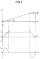
- the teta stroke of the manipulator is obtained by the combination of the brake motor 2 , the worm and wheel reducer 30 , the adjustable torque limiter 40 , the indexing mechanism 10 and the housing with springs 50 integral with the rotating frame 56 , using a law of movement A , B , C , D , function of the angle of rotation over a revolution, reproduced on the indexing mechanism 10 or on the cylindrical cam 6 , allowing to obtain a large range BC at constant speed Vc .
- Stops made in the BC range, at constant speed Vc are characterized by constant stopping precision, because they are always carried out under the same conditions. In tracks AB and CD the stops vary from one point to another; the stopping conditions at these points therefore also vary, which means that the stopping precision is variable.
- each stopping point has a control cam.
- the cylindrical cam makes several turns to achieve the maximum stroke.
- the spring box 50 (fig. 2) is placed between the mechanism 10 and the rotating frame 56 , so that , in case of blockage of the manipulation 7 , the indexing mechanism can carry out a displacement Y making it possible to cross point B or point C to reach the range at constant speed BC .
- the spring box 50 providing the connection between the indexing mechanism 10 and the rotating frame 56 , has three parts 51 , 52 and 53 stacked l 'one on the other and nested one inside the other, with a certain angle Y of maximum freedom of rotation rotation determined, in one direction as in the other, by precompressed springs 54 .
- the travel Y ' is limited by the mechanical stop 55 and the upper torque limiter 28 ensures the protection of the roller 8 and the cylindrical cam 6 , because we are, in this case, in the part BC of maximum pressure angle .
- the protection system consists only of the lower torque limiter 40 and the spring box 50 for the indexing tables, and the hollow base 7a with spring 23 and the limiters of torque 28 and 40 for multi-axis manipulators.
- the manipulator according to the invention is intended mainly for the loading, transfer and unloading of parts of all kinds.
Landscapes
- Engineering & Computer Science (AREA)
- Robotics (AREA)
- Mechanical Engineering (AREA)
- Manipulator (AREA)
- Jib Cranes (AREA)
- Surgical Instruments (AREA)
- Transmission Devices (AREA)
- Mechanical Control Devices (AREA)
- One-Way And Automatic Clutches, And Combinations Of Different Clutches (AREA)
Claims (6)
- Mehrachsiger mechanischer Manipulator mit einstellbarem Hub, bestehend aus einem Drehgestell, das mittels eines Verschiebeläufermotors, eines Rad- und Schneckengetriebes, eines Drehmomentbegrenzers und eines Indexiermechanismus mit vorab festgelegter Bewegungsgleichung dreht, und zu dem sich ein Manipulatorarm mittels einer mit einer Überlastungsschutzvorrichtung kombinierten Rolle, eines Nockenzylinders, dessen Drehbewegung von einem mit dem Drehgestell verbundenen Rad- und Schnecken-Getriebemotor gesteuert wird, bewegt, wobei ein Drehmomentbegrenzer dazwischen angeordnet ist, dadurch gekennzeichnet, daß die Drehmomentbegrenzer (28, 40) einstellbar sind, daß die Bewegungsgleichung des Indexiermechanismus (10) festgelegt ist, um eine gleichbleibende Geschwindigkeit über einen großen Bereich (BC), eventuell mit Haltepunkten, zu erhalten, daß das Drehgestell (56) über ein Federgehäuse (50) mit seinem Indexiermechanismus (10) verbunden ist, und daß die Überlastungsschutzvorrichtung, die mit der Antriebsrolle des Manipulatorarms (7) kombiniert ist, von einer Federplatte gebildet wird, die ein momentanes winkelmäßiges Ausweichen des Arms (7) ermöglicht, wenn dieser gegen ein Hemmnis stößt.
- Manipulator nach Anspruch 1,
dadurch gekennzeichnet, daß die Drehmomentbegrenzer (28, 40), die die Bewegung zum Nockenzylinder (6) bzw. zum Indexiermechanismus (10) übertragen, Federreibungsbegrenzer sind, deren Kraft direkt oder aus der Entfernung mit Verstellschrauben einstellbar sind. - Manipulator nach Anspruch 1,
dadurch gekennzeichnet, daß das Federgehäuse (50), das die Verbindung zwischen dem Drehgestell (56) und dem Indexiermechanismus (10) gewährleistet, in drei Teilen (51, 52 und 53) ausgeführt ist, die übereinanderliegen und mit einer bestimmten Drehfreiheits-Verschiebbarkeit Y zueinander ineinander verzahnt sind, die durch Federn (54) bestimmt wird, deren Pfeilhöhe Funktion des auf das Gehäuse übertragenen Drehmoments ist. - Manipulator nach Anspruch 1,
dadurch gekennzeichnet, daß die spannungsverstellbare Federplatte, die das winkelmäßige Ausweichen des Arms (7) ermöglicht, wenn dieser gegen ein Hemmnis stößt, von einem hohlen Fuß (7a) gebildet wird, der in einer Vertiefung (9a) an dem gleitenden Armhalter (9) mittels einer in dem gleitenden Armhalter (9) eingesetzten Gewindeachse festgesetzt wird, auf der eine Feder (23) sitzt, die an dem hohlen Fuß (7a) und an der Vorderseite einer Vorrichtung zum spannen der Feder (23) in Anlage kommt. - Manipulator nach Anspruch 4,
dadurch gekennzeichnet, daß die Vorrichtung zum Spannen der Feder (23) der Platte von einer Scheibe (24) und einer Mutter (25) gebildet wird. - Manipulator nach Anspruch 4,
dadurch gekennzeichnet, daß das winkelmäßige Ausweichen des Arms (7) von einem mechanischen Anschlag (55) begrenzt wird.
Priority Applications (1)
| Application Number | Priority Date | Filing Date | Title |
|---|---|---|---|
| AT8989902264T ATE104197T1 (de) | 1988-02-23 | 1989-01-30 | Mehrachsiger mechanischer manipulator mit ueberlastschutz. |
Applications Claiming Priority (3)
| Application Number | Priority Date | Filing Date | Title |
|---|---|---|---|
| FR8802280 | 1988-02-23 | ||
| FR8802280A FR2627419B1 (fr) | 1988-02-23 | 1988-02-23 | Manipulateur mecanique a axes multiples, a course reglable et a protection contre les surcharges |
| PCT/FR1989/000031 WO1989008012A1 (fr) | 1988-02-23 | 1989-01-30 | Manipulateur mecanique a axes multiples |
Publications (2)
| Publication Number | Publication Date |
|---|---|
| EP0358738A1 EP0358738A1 (de) | 1990-03-21 |
| EP0358738B1 true EP0358738B1 (de) | 1994-04-13 |
Family
ID=9363606
Family Applications (1)
| Application Number | Title | Priority Date | Filing Date |
|---|---|---|---|
| EP89902264A Expired - Lifetime EP0358738B1 (de) | 1988-02-23 | 1989-01-30 | Mehrachsiger mechanischer manipulator mit überlastschutz |
Country Status (10)
| Country | Link |
|---|---|
| US (1) | US5078021A (de) |
| EP (1) | EP0358738B1 (de) |
| JP (1) | JPH02503296A (de) |
| AT (1) | ATE104197T1 (de) |
| AU (1) | AU3046189A (de) |
| CA (1) | CA1329817C (de) |
| DE (1) | DE68914554T2 (de) |
| ES (1) | ES2015377A6 (de) |
| FR (1) | FR2627419B1 (de) |
| WO (1) | WO1989008012A1 (de) |
Families Citing this family (36)
| Publication number | Priority date | Publication date | Assignee | Title |
|---|---|---|---|---|
| CA2041051A1 (en) * | 1990-07-20 | 1992-01-21 | James D. Shaw | Dispensing mechanism |
| US5586616A (en) * | 1994-11-08 | 1996-12-24 | Ksenych; Nick | Rotatable scaffold |
| US5651396A (en) * | 1995-03-09 | 1997-07-29 | National Science Council | Variable pitch lead transmission mechanism for weft gripper strap drive |
| US5681210A (en) * | 1996-06-03 | 1997-10-28 | General Motors Corporation | Honing tool for elliptical cylinder bore |
| US6102355A (en) * | 1998-03-27 | 2000-08-15 | Rood; Richard K. | Motion imparting support for CRT monitors and similar devices |
| DE10112706B4 (de) * | 2001-03-16 | 2004-01-29 | Leica Microsystems Wetzlar Gmbh | Verstelleinheit |
| US6766996B1 (en) | 2001-07-16 | 2004-07-27 | Reid-Ashman Manufacturing, Inc. | Manipulator |
| DE10202826B4 (de) * | 2002-01-24 | 2005-05-04 | Wittenstein Motion Control Gmbh | Vorrichtung zum Betätigen von Türen von Fahrzeugen |
| GB0503150D0 (en) * | 2005-02-15 | 2005-03-23 | Mathews Mark O | Display device and stand therefor |
| US8356704B2 (en) | 2006-01-31 | 2013-01-22 | Andrew Flessas | Robotically controlled entertainment elements |
| US7545108B2 (en) * | 2006-01-31 | 2009-06-09 | Andy Flessas | Robotically controlled display |
| US9794533B2 (en) | 2006-01-31 | 2017-10-17 | Andrew Flessas | Robotically controlled entertainment elements |
| US11284048B2 (en) | 2006-01-31 | 2022-03-22 | Andrew Flessas | Robotically controlled display |
| DE102007028758B4 (de) * | 2007-06-22 | 2009-04-02 | Deutsches Zentrum für Luft- und Raumfahrt e.V. (DLR) | Roboter-Manipulator-Gelenkantrieb |
| CN101961824B (zh) * | 2010-08-10 | 2013-11-13 | 上海沪工焊接集团股份有限公司 | 一种应用于罐筒体环、纵缝焊机的传动系统 |
| EP2418366B1 (de) * | 2010-08-12 | 2013-03-13 | Cooper-Standard Automotive (Deutschland) GmbH | Aktuator für ein Wastegate oder eine variable Turbinengeometrie sowie Verwendung eines Aktuators für ein Wastegate oder eine variable Turbinengeometrie |
| EP2418373A1 (de) | 2010-08-12 | 2012-02-15 | Cooper-Standard Automotive (Deutschland) GmbH | Aktuator und Abgasrückführventil, Wastegate oder variable Turbinengeometrie eines Turboladers mit einem Aktuator |
| CN102380868B (zh) * | 2011-11-09 | 2014-04-16 | 广东工业大学 | 具有两维平动和一维转动的三自由度机械手 |
| US20130118298A1 (en) * | 2011-11-14 | 2013-05-16 | M-Tek, Inc. | Drive Assembly |
| CN102626929A (zh) * | 2012-04-06 | 2012-08-08 | 常熟市惠一机电有限公司 | 机械手的水平角度旋转机构 |
| CN102785068B (zh) * | 2012-07-27 | 2014-08-20 | 厦门精合电气自动化有限公司 | 一种机械手与转盘联动装置 |
| CN103465264B (zh) * | 2013-08-24 | 2015-06-17 | 浙江易锋机械有限公司 | 机械手传动机构 |
| WO2016025700A1 (en) * | 2014-08-15 | 2016-02-18 | Intuitive Surgical Operations, Inc. | Force transmission mechanism for surgical instrument, and related systems and methods |
| US9823693B2 (en) | 2014-08-26 | 2017-11-21 | Andrew Flessas | Robotically controlled convertible display |
| CN104440943B (zh) * | 2014-10-16 | 2016-09-28 | 中南大学 | 一种单驱动双动作输出的工业机械臂 |
| CN105618644B (zh) * | 2016-01-20 | 2017-05-24 | 东莞市开创精密机械有限公司 | 卷簧用刀匣三轴移动机构 |
| CN108161915A (zh) * | 2018-03-21 | 2018-06-15 | 东莞市特力精密夹具有限公司 | 一种电机驱动多轴组合机械臂系统 |
| CN108247675A (zh) * | 2018-03-21 | 2018-07-06 | 东莞市特力精密夹具有限公司 | 一种气缸式多轴组合机械臂系统 |
| CN108580719B (zh) * | 2018-04-11 | 2019-11-12 | 福州大学 | 一种用凸轮准确控制板料移动量的送进机构 |
| WO2021040714A1 (en) | 2019-08-29 | 2021-03-04 | Flessas Andrew | Method and system for moving cameras using robotic mounts |
| KR102732551B1 (ko) * | 2019-09-05 | 2024-11-21 | 삼성전자주식회사 | 길이 가변 구조의 암 유닛을 포함하는 로봇 |
| CN110802580A (zh) * | 2019-12-20 | 2020-02-18 | 东莞市三喜智能机器人有限公司 | 一种可拼接多轴机械臂 |
| US11425308B2 (en) | 2020-12-02 | 2022-08-23 | Andrew Flessas | Robotically movable display synchronously movable with robotically movable camera for displaying captured images in identical orientation |
| US11422632B1 (en) | 2021-08-27 | 2022-08-23 | Andrew Flessas | System and method for precise multi-dimensional movement of haptic stimulator |
| US20240075615A1 (en) * | 2022-08-12 | 2024-03-07 | Dexterity, Inc. | Robot with seven or more degrees of freedom |
| US20250369562A1 (en) * | 2024-05-31 | 2025-12-04 | Lockheed Martin Corporation | Adjustment assembly for display unit |
Family Cites Families (12)
| Publication number | Priority date | Publication date | Assignee | Title |
|---|---|---|---|---|
| US2579642A (en) * | 1948-10-12 | 1951-12-25 | Bachman Carl Otto | Mechanical movement |
| US3080765A (en) * | 1960-03-04 | 1963-03-12 | Warner Swasey Co | Device for actuating a movable member |
| US3359819A (en) * | 1966-04-25 | 1967-12-26 | Leo J Veillette | Bidirectional step torque filter with zero backlash characteristic |
| US3406583A (en) * | 1967-01-30 | 1968-10-22 | Gen Motors Corp | Drive mechanism having overload release means |
| US4293268A (en) * | 1979-09-21 | 1981-10-06 | George Mink | Material handling device |
| CA1142192A (en) * | 1979-03-12 | 1983-03-01 | George Mink | Material handling device |
| US4344729A (en) * | 1980-02-08 | 1982-08-17 | Bell And Howell Company | Break-away device |
| US4514616A (en) * | 1984-09-11 | 1985-04-30 | Rumble Equipment Limited | Safety mounting device |
| US4639184A (en) * | 1985-03-06 | 1987-01-27 | Process Equipment Company | Safety coupling device for robotic tooling |
| FR2587776B1 (fr) * | 1985-09-26 | 1989-10-20 | Mecanismes Comp Ind De | Dispositif amortisseur de couple dans un motoreducteur electrique destine a l'entrainement d'accessoires dans les vehicules automobiles |
| US4784421A (en) * | 1986-04-18 | 1988-11-15 | Mecanotron Corporation | Interchangeable tool mounting mechanism for robots |
| US4741642A (en) * | 1986-11-19 | 1988-05-03 | Phase 2 Automation | Safety joint for robotic arm |
-
1988
- 1988-02-23 FR FR8802280A patent/FR2627419B1/fr not_active Expired - Fee Related
-
1989
- 1989-01-30 WO PCT/FR1989/000031 patent/WO1989008012A1/fr not_active Ceased
- 1989-01-30 AT AT8989902264T patent/ATE104197T1/de active
- 1989-01-30 AU AU30461/89A patent/AU3046189A/en not_active Abandoned
- 1989-01-30 EP EP89902264A patent/EP0358738B1/de not_active Expired - Lifetime
- 1989-01-30 JP JP1502098A patent/JPH02503296A/ja active Pending
- 1989-01-30 US US07/427,113 patent/US5078021A/en not_active Expired - Fee Related
- 1989-01-30 DE DE68914554T patent/DE68914554T2/de not_active Expired - Fee Related
- 1989-02-22 CA CA000591817A patent/CA1329817C/fr not_active Expired - Fee Related
- 1989-02-23 ES ES8900656A patent/ES2015377A6/es not_active Expired - Fee Related
Also Published As
| Publication number | Publication date |
|---|---|
| ATE104197T1 (de) | 1994-04-15 |
| JPH02503296A (ja) | 1990-10-11 |
| ES2015377A6 (es) | 1990-08-16 |
| CA1329817C (fr) | 1994-05-24 |
| FR2627419B1 (fr) | 1990-07-27 |
| DE68914554T2 (de) | 1994-10-20 |
| US5078021A (en) | 1992-01-07 |
| DE68914554D1 (de) | 1994-05-19 |
| FR2627419A1 (fr) | 1989-08-25 |
| EP0358738A1 (de) | 1990-03-21 |
| WO1989008012A1 (fr) | 1989-09-08 |
| AU3046189A (en) | 1989-09-22 |
Similar Documents
| Publication | Publication Date | Title |
|---|---|---|
| EP0358738A1 (de) | Mehrachsiger mechanischer manipulator mit überlastschutz. | |
| EP2073228B1 (de) | Kompakte, robuste Steuerung für elektrische Mittel- und Hochspannungsgeräte | |
| BE898154A (fr) | Manipuleur pour positionner des pièces à usiner ou d'autres charges. | |
| FR2534412A1 (fr) | Interrupteur electrique avec arret de course du levier de commande en cas de soudure des contacts | |
| FR2600603A1 (fr) | Tendeur sur un enrouleur de ceinture de securite | |
| FR2642813A1 (fr) | Moyen d'entrainement a moteur electrique pour un organe de manoeuvre | |
| EP2829470B1 (de) | Vorrichtung zum Drehantrieb eines Luftfahrzeugrads | |
| EP1331658A1 (de) | Elektrischer Schaltvorrichtung mit Motorbetätigung und sein Steuerungsverfahren | |
| EP1237169B1 (de) | Hochspannungsschalter mit Federsteuerung und Zusatzfeder für Energie-Rückgewinnung | |
| FR2479548A1 (fr) | Interrupteur de fin de course d'arbre | |
| EP0438364B1 (de) | Drehantriebsvorrichtung für den Schrankenbaum einer beweglichen Schranke | |
| FR2611549A3 (fr) | Cisaille motorisee auto-alimentee | |
| FR2622945A1 (fr) | Mecanisme d'entrainement debrayable pour couronne tournante | |
| EP3562741B1 (de) | Antriebsvorrichtung | |
| EP3885233A1 (de) | Schienendetektor mit mechanischer zeitschaltuhr | |
| EP3676062B1 (de) | Mechanische vorrichtung mit passiver nachgiebigkeit zur übertragung einer drehbewegung | |
| EP0692605A1 (de) | Entkuppelbare Seilwinde | |
| EP1549818B1 (de) | Vorrichtung zum steuern eines motorisierten rolladens | |
| EP0516539A1 (de) | Vorrichtung zum Verschieben eines beweglichen Teiles von einer erste Stelle zu einer zweiten Stelle und zum Halten des Teiles in jeder dieser Stellen | |
| FR2469377A2 (fr) | Perfectionnements a un dispositif anti-chute automatique pour des installations de levage manuelles ou motorisees | |
| EP2073227B1 (de) | Kompakte, robuste Steuerung für elektrische Mittel- und Hochspannungsgeräte | |
| EP0019677B1 (de) | Aufrichtvorrichtung für Vertikal-Gyroskop | |
| FR2478532A1 (fr) | Dispositif de surveillance du synchronisme d'elements d'entrainement sur des machines-outils, et notamment sur des presses | |
| BE875496R (fr) | Dispositif anti-chute automatique pour installation de levage motorisee | |
| FR2695971A1 (fr) | Groupe de freinage avec déblocage de secours pour moteurs électriques. |
Legal Events
| Date | Code | Title | Description |
|---|---|---|---|
| PUAI | Public reference made under article 153(3) epc to a published international application that has entered the european phase |
Free format text: ORIGINAL CODE: 0009012 |
|
| 17P | Request for examination filed |
Effective date: 19891025 |
|
| AK | Designated contracting states |
Kind code of ref document: A1 Designated state(s): AT BE CH DE FR GB IT LI LU NL SE |
|
| 17Q | First examination report despatched |
Effective date: 19920717 |
|
| GRAA | (expected) grant |
Free format text: ORIGINAL CODE: 0009210 |
|
| AK | Designated contracting states |
Kind code of ref document: B1 Designated state(s): AT BE CH DE FR GB IT LI LU NL SE |
|
| PG25 | Lapsed in a contracting state [announced via postgrant information from national office to epo] |
Ref country code: SE Free format text: THE PATENT HAS BEEN ANNULLED BY A DECISION OF A NATIONAL AUTHORITY Effective date: 19940413 |
|
| REF | Corresponds to: |
Ref document number: 104197 Country of ref document: AT Date of ref document: 19940415 Kind code of ref document: T |
|
| REF | Corresponds to: |
Ref document number: 68914554 Country of ref document: DE Date of ref document: 19940519 |
|
| ITF | It: translation for a ep patent filed | ||
| GBT | Gb: translation of ep patent filed (gb section 77(6)(a)/1977) |
Effective date: 19940708 |
|
| PGFP | Annual fee paid to national office [announced via postgrant information from national office to epo] |
Ref country code: FR Payment date: 19950117 Year of fee payment: 7 |
|
| PG25 | Lapsed in a contracting state [announced via postgrant information from national office to epo] |
Ref country code: GB Effective date: 19950130 Ref country code: AT Effective date: 19950130 |
|
| PG25 | Lapsed in a contracting state [announced via postgrant information from national office to epo] |
Ref country code: LU Free format text: LAPSE BECAUSE OF NON-PAYMENT OF DUE FEES Effective date: 19950131 Ref country code: LI Effective date: 19950131 Ref country code: CH Effective date: 19950131 Ref country code: BE Effective date: 19950131 |
|
| PLBE | No opposition filed within time limit |
Free format text: ORIGINAL CODE: 0009261 |
|
| STAA | Information on the status of an ep patent application or granted ep patent |
Free format text: STATUS: NO OPPOSITION FILED WITHIN TIME LIMIT |
|
| PGFP | Annual fee paid to national office [announced via postgrant information from national office to epo] |
Ref country code: DE Payment date: 19950321 Year of fee payment: 7 |
|
| 26N | No opposition filed | ||
| BERE | Be: lapsed |
Owner name: S.A. SOPAP Effective date: 19950131 |
|
| PG25 | Lapsed in a contracting state [announced via postgrant information from national office to epo] |
Ref country code: NL Effective date: 19950801 |
|
| GBPC | Gb: european patent ceased through non-payment of renewal fee |
Effective date: 19950130 |
|
| REG | Reference to a national code |
Ref country code: CH Ref legal event code: PL |
|
| NLV4 | Nl: lapsed or anulled due to non-payment of the annual fee |
Effective date: 19950801 |
|
| PG25 | Lapsed in a contracting state [announced via postgrant information from national office to epo] |
Ref country code: FR Effective date: 19960930 |
|
| PG25 | Lapsed in a contracting state [announced via postgrant information from national office to epo] |
Ref country code: DE Effective date: 19961001 |
|
| REG | Reference to a national code |
Ref country code: FR Ref legal event code: ST |
|
| PG25 | Lapsed in a contracting state [announced via postgrant information from national office to epo] |
Ref country code: IT Free format text: LAPSE BECAUSE OF NON-PAYMENT OF DUE FEES Effective date: 20050130 |