EP0516562A1 - Faseroptische Strommessvorrichtung - Google Patents
Faseroptische Strommessvorrichtung Download PDFInfo
- Publication number
- EP0516562A1 EP0516562A1 EP92420166A EP92420166A EP0516562A1 EP 0516562 A1 EP0516562 A1 EP 0516562A1 EP 92420166 A EP92420166 A EP 92420166A EP 92420166 A EP92420166 A EP 92420166A EP 0516562 A1 EP0516562 A1 EP 0516562A1
- Authority
- EP
- European Patent Office
- Prior art keywords
- polarizer
- pieces
- separator
- fiber
- intensity
- Prior art date
- Legal status (The legal status is an assumption and is not a legal conclusion. Google has not performed a legal analysis and makes no representation as to the accuracy of the status listed.)
- Granted
Links
Images



Classifications
-
- G—PHYSICS
- G01—MEASURING; TESTING
- G01R—MEASURING ELECTRIC VARIABLES; MEASURING MAGNETIC VARIABLES
- G01R33/00—Arrangements or instruments for measuring magnetic variables
- G01R33/02—Measuring direction or magnitude of magnetic fields or magnetic flux
- G01R33/032—Measuring direction or magnitude of magnetic fields or magnetic flux using magneto-optic devices, e.g. Faraday or Cotton-Mouton effect
- G01R33/0322—Measuring direction or magnitude of magnetic fields or magnetic flux using magneto-optic devices, e.g. Faraday or Cotton-Mouton effect using the Faraday or Voigt effect
-
- G—PHYSICS
- G01—MEASURING; TESTING
- G01R—MEASURING ELECTRIC VARIABLES; MEASURING MAGNETIC VARIABLES
- G01R19/00—Arrangements for measuring currents or voltages or for indicating presence or sign thereof
- G01R19/25—Arrangements for measuring currents or voltages or for indicating presence or sign thereof using digital measurement techniques
-
- G—PHYSICS
- G01—MEASURING; TESTING
- G01R—MEASURING ELECTRIC VARIABLES; MEASURING MAGNETIC VARIABLES
- G01R15/00—Details of measuring arrangements of the types provided for in groups G01R17/00 - G01R29/00, G01R33/00 - G01R33/26 or G01R35/00
- G01R15/14—Adaptations providing voltage or current isolation, e.g. for high-voltage or high-current networks
- G01R15/24—Adaptations providing voltage or current isolation, e.g. for high-voltage or high-current networks using light-modulating devices
- G01R15/245—Adaptations providing voltage or current isolation, e.g. for high-voltage or high-current networks using light-modulating devices using magneto-optical modulators, e.g. based on the Faraday or Cotton-Mouton effect
- G01R15/246—Adaptations providing voltage or current isolation, e.g. for high-voltage or high-current networks using light-modulating devices using magneto-optical modulators, e.g. based on the Faraday or Cotton-Mouton effect based on the Faraday, i.e. linear magneto-optic, effect
Definitions
- the present invention relates to a device for measuring current by optical fiber, the measuring principle of which is based on the FARADAY effect in a single-mode optical fiber.
- the light emission in the single mode optical fiber is achieved by the use of a laser diode which is the required monochromatic light source.
- the first configuration uses a so-called "90 °" detection.
- the measurement of the angle F is then carried out by separating the light wave leaving the optical fiber into two light waves linearly polarized at 90 ° from one another.
- a 90 ° separator-polarizer cube is used, which is a commercial element.
- Each of these two light waves is received on a respective photodiode, the current supplied of which is measured respectively, I1 and I2.
- a separator / polarizer cube has the disadvantage of having a polarization rate of 1 to 2% in intensity on each channel, which introduces a fairly penalizing signal distortion. Furthermore, such a separator cube is of rather high cost, which heavily penalizes the cost price of the sensor.
- the second configuration mentioned in this article uses a so-called "45 °" detection which has the advantage of allowing the use of a single winding of optical fiber to cover a wide range of current intensities to be measured.
- the light beam coming from the optical fiber after rotation F is separated into two components linearly polarized in two directions making between them an angle of 45 °, and not 90 ° as in the previous case.
- 45 ° separator-polarizer cube the practical application of this process involves the use of a semi-reflecting plate and two WOLLASTON prisms each connected to a photodiode, which is even heavier and more expensive than the previous realization.
- I1 Io (1 + cos 2F) / 4
- I2 Io (1+ sin 2F) / 4
- Io is the intensity corresponding to the light source emitted by the aforementioned laser diode.
- Determining sin 2F and cos 2F requires first determining the intensity Io corresponding to the source.
- this value Io is determined by the use of a semi-reflecting plate, located upstream of the optical fiber and of a photodiode, which makes this type of installation even more cumbersome.
- the invention aims to remedy these drawbacks. To this end, it relates to a device for measuring the intensity of the current passing through a conductor, a device comprising a single-mode optical fiber making a predetermined number of turns around the conductor and traversed by a linearly polarized light wave, supplied by a laser diode.
- the measuring device comprises, at the output of the optical fiber, a polarizer-separator made up of at least two pieces of polarizing sheet, crossed by the light beam from of the fiber, the relative polarizations of the pieces of polarizing sheet making between them predetermined angles, a photodiode respec tive associated with each of the pieces of sheet detecting the respective currents corresponding to their illumination, each of these photodiodes being connected to an electronic unit able to carry out the calculation of the angle rotation accordingly and to deduce therefrom value of the intensity to be measured.
- the polarizer-separator comprises two separate coplanar pieces, substantially orthogonal to the axis of the light beam, the sheet pieces being two half-discs of the same diameter, placed substantially edge to edge, so as to reconstitute a complete and coaxial disc. to the light beam leaving the fiber, the angle formed between the polarizations of the two pieces being 90 ° or 45 °.
- the two aforementioned photodiodes are advantageously constituted by a bi-quadrant photodetector, advantageously in the form of a disc substantially of the same diameter as that reconstituted by the two pieces of polarizing sheets, the bi-quadrant photodetector being positioned downstream coaxially and at a short distance from the two contiguous pieces of polarizing sheets in half-disc.
- the intensity Io of the light source can be calculated from the measured currents. It can also be determined at the output of the optical fiber, for example by means of a photodiode directly receiving the light leaving this fiber and placed behind a preferentially central orifice provided in the polarizing separator produced by the two pieces of polarizing sheet. According to another variant, the intensity Io is determined by means of a photodiode receiving the light coming from the optical fiber and then reflected either by a mirror preferably placed on the same support as that carrying the two pieces of sheet, or by both leaf pieces themselves.
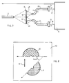
- Figures 1 and 2 show a device for measuring optically the intensity I of the current flowing through a conductor 1, this intensity being for example of the order of a few tens of thousands of amperes to fix ideas.
- the device uses the FARADAY effect, or "FARADAY rotation” of angle F, which is created in an optical fiber 2, single mode, weakly birefringent, and traversed by a monochromatic and linearly polarized light wave, which is applied to it by a diode emitting laser 3, with preferential interposition of a lens 4 for focusing the light emitted by the diode 3.
- the emitting laser diode 3 is itself supplied with electrical energy by a connection 4 connected to an electronic unit 5, which is the power supply and analysis unit of the device.
- the measurement of the angle F is carried out by a so-called "90 °" detection, for which it is necessary to separate the light beam 8 at output 7 from the fiber 2, in two beams whose axes of polarization are perpendicular to each other.
- the two pieces 10 and 11 each have a half-disc shape of the same diameter, and are joined against each other by their cutting diameter so as to reconstitute together an entire disc 9 (see in Figure 2) which is preferably orthogonal to the axis 30 of the light beam outgoing 8, and which has the same axis 30.
- each of these coplanar polarizing half-discs 10,11 are detected by two respective photodiodes 14,15 which are attached to the separator-polarizer, behind the latter. Very simply, they are constituted by the two respective halves 14, 15 of a circular bi-quadrant photodetector 16 on the market, which is chosen with a diameter equal to that of the separator-polarizer 9.
- the intensities I1 and I2 of the currents detected at the output of the photodiodes 14 and 15 are measured and processed by the aforementioned electronic unit 5, to which the photodiodes are connected by connections 17 and 18.
- the cancellation of the optical activity due to temperature variations is advantageously carried out by performing a double reverse twist of the optical fiber 2.
- Each half length of fiber is twisted at twist rates equal, but in opposite directions.
- Thermal compensation is also advantageously carried out also by the processing carried out by the electronic unit 5.
- the detection module 9 , 16 itself is made free to rotate, which avoids having to rotate the fiber 2 to achieve the zero current adjustment. Furthermore, it is advantageously provided for the possibility of precisely adjusting the orthogonality of the directions of polarization 12 and 13 in allowing a certain rotation of the half-discs 10 and 11 relative to each other.
- FIGS. 3 and 4 show in detail the detection module proper.
- the detection module comprises an overall support part, or chassis, 19 in the form of a vertical wall pierced with a circular orifice 20 which receives a circular guide, or cover, 21 held in position by screws 22, of which only the axis is shown diagrammatically in FIG. 3.
- a base 24 which carries the optical fiber 2 and which is held in position by screws 25.
- the base 24, and therefore the fiber (2), are therefore mounted fixed in chassis 19.
- the upper polarizing half-disc 10 is glued by its periphery to a brass piece 26.
- the lower polarizing half-disc 11 is glued by its periphery to another brass piece 27.
- the parts 26, 27 are not only arranged and positioned so that the half-discs 10 and 11 together form a complete disc 9 coaxial with the fiber 2 and orthogonal to its outlet axis 30, but also are nested one inside the other to allow them to rotate relative able to allow fine adjustment to the optical bench of the orthogonality of the privileged polarization axes 12 and 13.
- the blocking in the desired position is then carried out by screws 28 which ensure the fixing and tightening of the supports 26,27 against a cover 29.
- the two support and adjustment pieces 26 and 27 are also held in a cover 31 which is itself secured to the cover 29 by screws 32.
- the bi-quadrant photodiode 16 and its connection pin 33 are moreover fixed on an external support 34 which is rendered secured to the cover 31 by screws 35.
- the cover 31 is itself held by a locking washer 36 which is secured to the part 21 by screws 37.
- the parts 26, 27, 28, 29, 31, 34 form a rigid assembly which, after loosening the locking screws 37, can rotate in the guide 21 secured to the assembly support 19.
- the above-mentioned zero current adjustment is therefore produced, without touching the fiber 2, by rotation of the rigid assembly, which is then locked in position by tightening the screws 37.
- the invention is also applicable, and in a particularly advantageous manner, to a so-called "45 °" detection, and a preferred embodiment of the corresponding detection module is schematically represented in FIGS. 5 and 6.
- Io intensity corresponding to the light emitted by the source 3.
- the determination of Io is carried out simply by the fact that the separator-polarizer disc 9 and the bi-quadrant photodetector 16 are each pierced with a small axial orifice, respectively 38 and 39, these two orifices coaxial being substantially the same diameters.
- An auxiliary photodiode 41 is attached to the photodetector 16, behind the latter, and the intensity Io which it thus detects is introduced, by a conductor 42, for exploitation in the electronic unit 5.
- An alternative, also advantageous, would consist in not providing orifices 38 and 39 in the discs 9 and 16, but to stick on the disc 9, for example at the upper part as shown in phantom, and on the face located screw opposite the fiber outlet 7, a small reflecting mirror 43, associated with a measuring photo-diode 44 receiving the beam reflected by the mirror and connected to the block 5 by a connection 45. It can also be envisaged to measure Io from the light directly reflected by the polarizer.
- the two previous embodiments are compact embodiments, for which it is desired that the photodetectors are practically attached to the polarizer-separators. This is of course not the only possibility and, if it is on the contrary desired that the measurement photodetectors be distant from the fiber 2, and consequently from the conductor 1, it is possible, as shown diagrammatically in FIG. 7, to deport the photodetectors.
- this is, for example, a detection module "90 °", which has the same separator-polarizer disc 9 as in Figure 1, but for which the photodetectors 14 and 15, standard, are remotely remote by means of two additional optical fibers 46 and 47 associated with two focusing lenses 48 and 49.
- an auxiliary fiber would then have to be provided placed at the outlet of the central orifice 38 of the disc 9.
- FIG. 8 A convenient means for producing, in one case as in the other, the separator-polarizer disc 9, is shown diagrammatically in FIG. 8. It consists in obtaining commercially a polarizing sheet 50, of preferred polarization direction 51, then to cut, preferably by laser beam, from this sheet 50, two half-discs 10 and 11 oriented on this sheet at the desired angle X, here equal to 45 °.
- the invention is not limited to a separator-polarizer (9) consisting of two pieces. It applies in a similar manner to a separator-polarizer in three or four pieces, as illustrated for example in FIGS. 9 and 10.
- the separator-polarizer is made up of three pieces.
- the direction 53 of polarization of one of the pieces makes an angle of 90 ° with the direction of polarization 54 of a second piece, also in the form of a quarter disc in the figure. , and an angle of 45 ° with the direction of polarization 55 of the third piece.
- the latter is, in the embodiment shown, consisting of a half-disc, the three pieces being joined so as to constitute a disc.
- a suitable photodetector is arranged downstream of the separator-polarizer to collect the corresponding signals.
- the separator-polarizer 56 according to Figure 10 consists of four pieces, each forming a quarter disc.
- Io 2 (I3 + I4 + I6 + I7) and deduce the value of F.
Landscapes
- Engineering & Computer Science (AREA)
- Power Engineering (AREA)
- Physics & Mathematics (AREA)
- General Physics & Mathematics (AREA)
- Condensed Matter Physics & Semiconductors (AREA)
- Measuring Instrument Details And Bridges, And Automatic Balancing Devices (AREA)
- Measurement Of Current Or Voltage (AREA)
- Optical Transform (AREA)
- Investigating Or Analysing Materials By Optical Means (AREA)
Applications Claiming Priority (2)
| Application Number | Priority Date | Filing Date | Title |
|---|---|---|---|
| FR9106485A FR2677130B1 (fr) | 1991-05-27 | 1991-05-27 | Dispositif de mesure de courant par fibre optique. |
| FR9106485 | 1991-05-27 |
Publications (2)
| Publication Number | Publication Date |
|---|---|
| EP0516562A1 true EP0516562A1 (de) | 1992-12-02 |
| EP0516562B1 EP0516562B1 (de) | 1996-08-28 |
Family
ID=9413255
Family Applications (1)
| Application Number | Title | Priority Date | Filing Date |
|---|---|---|---|
| EP92420166A Expired - Lifetime EP0516562B1 (de) | 1991-05-27 | 1992-05-21 | Faseroptische Strommessvorrichtung |
Country Status (8)
| Country | Link |
|---|---|
| US (1) | US5256872A (de) |
| EP (1) | EP0516562B1 (de) |
| JP (1) | JP3160068B2 (de) |
| KR (1) | KR920021992A (de) |
| BR (1) | BR9201983A (de) |
| CA (1) | CA2068901C (de) |
| DE (1) | DE69213102T2 (de) |
| FR (1) | FR2677130B1 (de) |
Families Citing this family (6)
| Publication number | Priority date | Publication date | Assignee | Title |
|---|---|---|---|---|
| US5365175A (en) * | 1993-01-21 | 1994-11-15 | The United States Of America As Represented By The Administrator Of The National Aeronautics And Space Administration | Method of locating ground faults |
| EP0959112B1 (de) | 1998-05-20 | 2003-08-06 | Seiko Epson Corporation | Reaktionslösung für Tintenstrahldruckaufzeichnung und Tintenstrahlaufzeichnungsverfahren, die diese benutzt |
| US6488751B1 (en) | 1998-10-08 | 2002-12-03 | Seiko Epson Corporation | Ink set for ink jet recording and ink jet recording method |
| KR100428891B1 (ko) * | 2001-12-21 | 2004-04-29 | 재단법인 포항산업과학연구원 | 레이저를 이용한 비접촉식 전류 측정장치 |
| US8894197B2 (en) | 2007-03-01 | 2014-11-25 | Seiko Epson Corporation | Ink set, ink-jet recording method, and recorded material |
| JP5552856B2 (ja) | 2010-03-24 | 2014-07-16 | セイコーエプソン株式会社 | インクジェット記録方法および記録物 |
Citations (3)
| Publication number | Priority date | Publication date | Assignee | Title |
|---|---|---|---|---|
| FR2097299A5 (de) * | 1970-07-01 | 1972-03-03 | Alsthom Savoisienne | |
| FR2622969A1 (fr) * | 1987-11-05 | 1989-05-12 | Gen Electric | Debitmetre avec affichage par commutateur optique a effet de faraday |
| EP0430060A1 (de) * | 1989-12-01 | 1991-06-05 | Asea Brown Boveri Ag | Faseroptischer Stromwandler |
Family Cites Families (2)
| Publication number | Priority date | Publication date | Assignee | Title |
|---|---|---|---|---|
| DE2835794C3 (de) * | 1978-08-16 | 1987-12-03 | Max-Planck-Gesellschaft zur Förderung der Wissenschaften eV, 3400 Göttingen | Faseroptische Anordnung zur Messung der Stärke eines elektrischen Stromes |
| CH661985A5 (de) * | 1984-01-24 | 1987-08-31 | Mettler Instrumente Ag | Verfahren zur kraftmessung mit hilfe der spannungsinduzierten doppelbrechung in einem monomode-lichtleiter und messanordnung zur durchfuehrung des verfahrens. |
-
1991
- 1991-05-27 FR FR9106485A patent/FR2677130B1/fr not_active Expired - Fee Related
-
1992
- 1992-05-14 US US07/883,204 patent/US5256872A/en not_active Expired - Fee Related
- 1992-05-19 CA CA002068901A patent/CA2068901C/en not_active Expired - Fee Related
- 1992-05-21 JP JP12902592A patent/JP3160068B2/ja not_active Expired - Fee Related
- 1992-05-21 DE DE69213102T patent/DE69213102T2/de not_active Expired - Fee Related
- 1992-05-21 EP EP92420166A patent/EP0516562B1/de not_active Expired - Lifetime
- 1992-05-26 BR BR929201983A patent/BR9201983A/pt not_active Application Discontinuation
- 1992-05-27 KR KR1019920009059A patent/KR920021992A/ko not_active Ceased
Patent Citations (3)
| Publication number | Priority date | Publication date | Assignee | Title |
|---|---|---|---|---|
| FR2097299A5 (de) * | 1970-07-01 | 1972-03-03 | Alsthom Savoisienne | |
| FR2622969A1 (fr) * | 1987-11-05 | 1989-05-12 | Gen Electric | Debitmetre avec affichage par commutateur optique a effet de faraday |
| EP0430060A1 (de) * | 1989-12-01 | 1991-06-05 | Asea Brown Boveri Ag | Faseroptischer Stromwandler |
Non-Patent Citations (2)
| Title |
|---|
| ELECTRONICS LETTERS, vol. 19, no. 15, 21 juillet 1983, pages 578-579, Enage, GB; J. LIZET et al.: "Reduction of temperature and vibration sensitivity of a polarimetric current sensor" * |
| REVUE GENERALE DE L'ELECTRICITE, no. 4, avril 1990, pages 62-67, Paris, FR; P. ROYER et al.: "Capteur de courant à fibre optique" * |
Also Published As
| Publication number | Publication date |
|---|---|
| DE69213102D1 (de) | 1996-10-02 |
| BR9201983A (pt) | 1993-01-12 |
| KR920021992A (ko) | 1992-12-19 |
| CA2068901A1 (en) | 1992-11-28 |
| JPH0627152A (ja) | 1994-02-04 |
| EP0516562B1 (de) | 1996-08-28 |
| JP3160068B2 (ja) | 2001-04-23 |
| US5256872A (en) | 1993-10-26 |
| CA2068901C (en) | 2000-12-05 |
| FR2677130A1 (fr) | 1992-12-04 |
| FR2677130B1 (fr) | 1994-07-08 |
| DE69213102T2 (de) | 1997-02-20 |
Similar Documents
| Publication | Publication Date | Title |
|---|---|---|
| EP3120134B1 (de) | Vorrichtung und verfahren zur polarimetrischen fernbestimmung | |
| FR2491615A1 (fr) | Procede de mesure optoelectronique et dispositifs pour la determination de la qualite de surfaces a reflexion diffuse | |
| EP0291394A1 (de) | Bewegungssensor mit zurückgesetzten optischen Fasern | |
| SG50599A1 (en) | Optical gap measuring apparatus and method | |
| FR2690012A1 (fr) | Procédé de réglage d'une source lumineuse continûment syntonisable. | |
| EP2063300A1 (de) | Kanal von sehr hoher qualität für optische mehrwege-drehkupplung | |
| FR2515811A1 (fr) | Dispositif interferometrique de mesure de champ magnetique et capteur de courant electrique comportant un tel dispositif | |
| EP0453693B1 (de) | Pockelseffekt-Messsonde für elektrische Felder | |
| EP0516562B1 (de) | Faseroptische Strommessvorrichtung | |
| EP0018873B1 (de) | Kompakte optische Koppelungsvorrichtung und solch eine Vorrichtung enthaltender interferometrischer Gyrometer mit einer optischen Faser | |
| EP0396191B1 (de) | Druckwandler mit optischer Faser | |
| EP0237415A1 (de) | Vorrichtung zur spektralphotometrischen Ellipsometrie mit Verwendung optischer Fasern | |
| US8947072B2 (en) | Conductor to which current detection head is fixed, and current detection head used in manufacture of same | |
| EP0136955B1 (de) | Anordnung zum Messen des Gradienten eines magnetischen Feldes durch magneto-optischen Effekt | |
| FR2542878A1 (fr) | Dispositif de balayage | |
| EP0152706A1 (de) | Polarisationsfernmessgerät | |
| CH369903A (fr) | Procédé pour la détermination d'une propriété optique d'une couche superficielle d'un milieu transparent et appareil pour la mise en oeuvre de ce procédé | |
| EP0065429A1 (de) | Verfahren und Vorrichtung zur optischen Wegmessung und Verwendung zur schrittweisen Photoreproduktion | |
| EP1674878B1 (de) | Elektrooptische Sonde zur Messung elektrischer oder elektromagnetischer Felder mit einer Steuerung der Wellenlänge des Betriebspunkts | |
| EP0754955A1 (de) | Verfahren zur differentiellen Messung des Einfallswinkels eines Lichtstrahles und Vorrichtung zur Durchführung des Verfahrens | |
| FR2657161A1 (fr) | Dispositif de detection a distance d'une grandeur physique, fonctionnant en reflexion. | |
| EP0613017B1 (de) | Vorrichtung zur optischen Messung der elektrischen Stromstärke | |
| FR2565683A1 (fr) | Capteur optique, par exemple de pression, a longueur d'onde unique | |
| FR2906039A1 (fr) | Procede et dispositif pour caracteriser un signal electrique se propageant dans un echantillon. | |
| FR2636744A1 (fr) | Resonateur vibrant a excitation et detection optique a usage capteur |
Legal Events
| Date | Code | Title | Description |
|---|---|---|---|
| PUAI | Public reference made under article 153(3) epc to a published international application that has entered the european phase |
Free format text: ORIGINAL CODE: 0009012 |
|
| AK | Designated contracting states |
Kind code of ref document: A1 Designated state(s): CH DE GB IT LI SE |
|
| 17P | Request for examination filed |
Effective date: 19930513 |
|
| RAP1 | Party data changed (applicant data changed or rights of an application transferred) |
Owner name: SCHNEIDER ELECTRIC SA |
|
| 17Q | First examination report despatched |
Effective date: 19950522 |
|
| GRAH | Despatch of communication of intention to grant a patent |
Free format text: ORIGINAL CODE: EPIDOS IGRA |
|
| GRAH | Despatch of communication of intention to grant a patent |
Free format text: ORIGINAL CODE: EPIDOS IGRA |
|
| GRAA | (expected) grant |
Free format text: ORIGINAL CODE: 0009210 |
|
| AK | Designated contracting states |
Kind code of ref document: B1 Designated state(s): CH DE GB IT LI SE |
|
| PG25 | Lapsed in a contracting state [announced via postgrant information from national office to epo] |
Ref country code: IT Free format text: LAPSE BECAUSE OF FAILURE TO SUBMIT A TRANSLATION OF THE DESCRIPTION OR TO PAY THE FEE WITHIN THE PRE;WARNING: LAPSES OF ITALIAN PATENTS WITH EFFECTIVE DATE BEFORE 2007 MAY HAVE OCCURRED AT ANY TIME BEFORE 2007. THE CORRECT EFFECTIVE DATE MAY BE DIFFERENT FROM THE ONE RECORDED.SCRIBED TIME-LIMIT Effective date: 19960828 |
|
| REF | Corresponds to: |
Ref document number: 69213102 Country of ref document: DE Date of ref document: 19961002 |
|
| GBT | Gb: translation of ep patent filed (gb section 77(6)(a)/1977) |
Effective date: 19961001 |
|
| PGFP | Annual fee paid to national office [announced via postgrant information from national office to epo] |
Ref country code: CH Payment date: 19970610 Year of fee payment: 6 |
|
| PLBE | No opposition filed within time limit |
Free format text: ORIGINAL CODE: 0009261 |
|
| 26N | No opposition filed | ||
| PG25 | Lapsed in a contracting state [announced via postgrant information from national office to epo] |
Ref country code: LI Free format text: LAPSE BECAUSE OF NON-PAYMENT OF DUE FEES Effective date: 19980531 Ref country code: CH Free format text: LAPSE BECAUSE OF NON-PAYMENT OF DUE FEES Effective date: 19980531 |
|
| REG | Reference to a national code |
Ref country code: CH Ref legal event code: PL |
|
| PGFP | Annual fee paid to national office [announced via postgrant information from national office to epo] |
Ref country code: SE Payment date: 20010417 Year of fee payment: 10 |
|
| PGFP | Annual fee paid to national office [announced via postgrant information from national office to epo] |
Ref country code: DE Payment date: 20010507 Year of fee payment: 10 |
|
| PGFP | Annual fee paid to national office [announced via postgrant information from national office to epo] |
Ref country code: GB Payment date: 20010516 Year of fee payment: 10 |
|
| REG | Reference to a national code |
Ref country code: GB Ref legal event code: IF02 |
|
| PG25 | Lapsed in a contracting state [announced via postgrant information from national office to epo] |
Ref country code: GB Free format text: LAPSE BECAUSE OF NON-PAYMENT OF DUE FEES Effective date: 20020521 |
|
| PG25 | Lapsed in a contracting state [announced via postgrant information from national office to epo] |
Ref country code: SE Free format text: LAPSE BECAUSE OF NON-PAYMENT OF DUE FEES Effective date: 20020522 |
|
| PG25 | Lapsed in a contracting state [announced via postgrant information from national office to epo] |
Ref country code: DE Free format text: LAPSE BECAUSE OF NON-PAYMENT OF DUE FEES Effective date: 20021203 |
|
| EUG | Se: european patent has lapsed | ||
| GBPC | Gb: european patent ceased through non-payment of renewal fee |
Effective date: 20020521 |