EP0516706B1 - A guide for a cutting band - Google Patents
A guide for a cutting band Download PDFInfo
- Publication number
- EP0516706B1 EP0516706B1 EP91905010A EP91905010A EP0516706B1 EP 0516706 B1 EP0516706 B1 EP 0516706B1 EP 91905010 A EP91905010 A EP 91905010A EP 91905010 A EP91905010 A EP 91905010A EP 0516706 B1 EP0516706 B1 EP 0516706B1
- Authority
- EP
- European Patent Office
- Prior art keywords
- guide
- band
- cutting
- rings
- side faces
- Prior art date
- Legal status (The legal status is an assumption and is not a legal conclusion. Google has not performed a legal analysis and makes no representation as to the accuracy of the status listed.)
- Expired - Lifetime
Links
- 238000005520 cutting process Methods 0.000 title claims abstract description 51
- 238000004140 cleaning Methods 0.000 claims description 5
- 239000000428 dust Substances 0.000 claims description 5
- 230000001788 irregular Effects 0.000 abstract description 2
- 230000015572 biosynthetic process Effects 0.000 description 6
- 229910000831 Steel Inorganic materials 0.000 description 4
- XAGFODPZIPBFFR-UHFFFAOYSA-N aluminium Chemical compound [Al] XAGFODPZIPBFFR-UHFFFAOYSA-N 0.000 description 4
- 229910052782 aluminium Inorganic materials 0.000 description 4
- 239000004411 aluminium Substances 0.000 description 4
- 239000000463 material Substances 0.000 description 4
- 239000010959 steel Substances 0.000 description 4
- 229910000760 Hardened steel Inorganic materials 0.000 description 2
- 229910001208 Crucible steel Inorganic materials 0.000 description 1
- 239000000919 ceramic Substances 0.000 description 1
- 238000005524 ceramic coating Methods 0.000 description 1
- 239000011248 coating agent Substances 0.000 description 1
- 238000000576 coating method Methods 0.000 description 1
- 238000010276 construction Methods 0.000 description 1
- 238000005265 energy consumption Methods 0.000 description 1
- 239000011121 hardwood Substances 0.000 description 1
- 238000004519 manufacturing process Methods 0.000 description 1
- 235000012054 meals Nutrition 0.000 description 1
- 235000013372 meat Nutrition 0.000 description 1
Images



Classifications
-
- B—PERFORMING OPERATIONS; TRANSPORTING
- B26—HAND CUTTING TOOLS; CUTTING; SEVERING
- B26D—CUTTING; DETAILS COMMON TO MACHINES FOR PERFORATING, PUNCHING, CUTTING-OUT, STAMPING-OUT OR SEVERING
- B26D1/00—Cutting through work characterised by the nature or movement of the cutting member or particular materials not otherwise provided for; Apparatus or machines therefor; Cutting members therefor
- B26D1/01—Cutting through work characterised by the nature or movement of the cutting member or particular materials not otherwise provided for; Apparatus or machines therefor; Cutting members therefor involving a cutting member which does not travel with the work
- B26D1/46—Cutting through work characterised by the nature or movement of the cutting member or particular materials not otherwise provided for; Apparatus or machines therefor; Cutting members therefor involving a cutting member which does not travel with the work having an endless band-knife or the like
- B26D1/54—Guides for band-knives or the like
-
- B—PERFORMING OPERATIONS; TRANSPORTING
- B23—MACHINE TOOLS; METAL-WORKING NOT OTHERWISE PROVIDED FOR
- B23D—PLANING; SLOTTING; SHEARING; BROACHING; SAWING; FILING; SCRAPING; LIKE OPERATIONS FOR WORKING METAL BY REMOVING MATERIAL, NOT OTHERWISE PROVIDED FOR
- B23D55/00—Sawing machines or sawing devices working with strap saw blades, characterised only by constructional features of particular parts
- B23D55/08—Sawing machines or sawing devices working with strap saw blades, characterised only by constructional features of particular parts of devices for guiding or feeding strap saw blades
- B23D55/082—Devices for guiding strap saw blades
Definitions
- the invention relates to a guide for an endless cutting band in the form of a saw or knife blade running over at least two wheels in a cutting machine, as described in the preamble of claim 1.
- the rotation of the guide means ensures that sporadic wear of the guide faces will never occur and that performance remains steady permitting accuracy and a cutting of a hitherto unknown good quality.
- the guide can be fitted close to the workpiece whereby the most accurate cutting is obtained. Guiding is furthermore performed without any significant noise development, and since the loading of the band is reduced, the band can be given smaller dimensions which makes it cheaper to produce and operate.
- the guide can be adjusted to any required band thickness and, when worn one or a number of the rings can be replaced or removed.
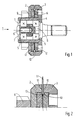
- Figs. 1 and 2 show an example of a rotary guide 1 which is mounted on a shaft 6 which can be attached to a machine part.
- FIG. 4 An example of such a fitting is shown in fig. 4 where the shaft 6 is attached to a machine part 16 by means of a nut 15.
- a hub 4 On the outside of the bearings 5 a hub 4 is provided which is held by means of a locking ring 7 in an interior groove in the hub.
- the hub 4 At its end the hub 4 is provided with a flange forming one of the lateral guide rings 3 which on the outside forms a side face 10.
- the opposite side face is formed in a guide ring 2 being attached to the hub 4 by means of a nut 9.
- a recess for a pair of wearing rings 12 each having a bevel 13 extending on a plane at right angles to the axis of rotation and in the centre of the two lateral guide faces 10.
- one or a number of distance rings 14 are provided between the steel rings 12.
- the guide shown in figs. 1 and 2 is especially suited for double-edged knife bands 11 in that this allows the band to be laterally guided by means of the side faces 10, and at the rear edge by the V-groove formed by the bevels 13 in that, as shown more clearly in fig. 2, guiding and control is effected on both sides of the knife edge without causing damage to the edge proper, because this extends in the groove between the rings 12 which by means of distance rings 14 are at a certain distance to each other.
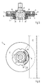
- Fig. 3 shows an example of the use of the guide shown in figs. 1 and 2 for construction of a double guide for a double-edged cutting band 11.
- the guides 1 are slightly staggered in the direction of motion of the knife in order to guide both knife edges in the two V-grooves 13 just as the sides of the knife 11 can be guided in the full width of the knife by the two sets of lateral guides 10.
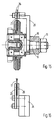
- Figs. 5, 6 and 7 show an embodiment of a guide 1 whose side piece is formed by side faces 10 being arranged directly on the side rings 2, 3.
- These rings 2, 3 can be made of a lighter material such as aluminium, and the side faces 10 can be configured as a hard wear-resisting coating thereon.
- the end guide face or bottom face 19 is a steel ring or a similar hard material 18 which is held in a recess and with a distance ring 20 at the side for the formation of the required distance between the side faces 10, corresponding to the thickness of a saw band 17, which is thereby allowed to run just between the lateral guides 10.
- the rings 2, 3 can be made of hardened steel.
- Fig. 8 shows an example of a guide made of a light material, such as aluminium which is subsequently provided with wearing rings 23 for the formation of the lateral guides 10, and with a ring portion 18 for the formation of the rear guide face 19 for the rear edge of the saw band 17.
- Fig. 9 shows an example of a guide with aluminium guide rings 2, 3 which are provided with a ceramic coating 21 at one side and which furthermore have a ring portion at the interior for the formation of the bottom guide face 19, and which at the other side are provided with a ring 22 for the formation of the opposite wear face.
- distance rings 20 are provided for adjustment of the distance between the lateral guide faces 10.
- Fig. 10 shows an example of a guide 1 without recess in the one lateral guide 3.
- the recess is found only in the other lateral guide 2 so that the steel ring 18 can be inserted for determination of the width between the lateral guide faces 10 and the bottom guide face 19 for the saw blade 17.
- Such a guide is advantageously made of cast steel which is subsequently hardened.
- figs. 11 and 12 show an example of a guide 1 with lateral guide rings 2, 3 whose recess is uniform and so wide that steel rings 18 with different largest diameters can be inserted for the formation of the bottom face 19 which can be adapted to saw bands 17 of varying widths.
- distance rings 20 can be inserted as previously mentioned.
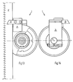
- a holder 24 is secured on the shaft 6, and to this holder there is attached partly a dust collecting plate 25 extending down into the guide groove behind the saw band 17 as shown in figs. 13 - 16, and partly a dust collecting plate 26 extending on both sides of the band 17 thereby cleaning the band of dust and other refuse, such as saw meal during operation.
- the guide can be used for cutting knives or cutting saws in slaughterhouse machinery or the like, thereby eliminating any risk of disturbing the performance of the guide or the band.
- the equipment is easily disassembled permitting replacement or partial removal of distance rings so that the distance between the lateral guide faces is constantly adapted to the thickness of the band.
Landscapes
- Engineering & Computer Science (AREA)
- Mechanical Engineering (AREA)
- Life Sciences & Earth Sciences (AREA)
- Forests & Forestry (AREA)
- Sawing (AREA)
- Polishing Bodies And Polishing Tools (AREA)
- Surface Acoustic Wave Elements And Circuit Networks Thereof (AREA)
- Nonmetal Cutting Devices (AREA)
- Treatment Of Fiber Materials (AREA)
- Control And Other Processes For Unpacking Of Materials (AREA)
- Basic Packing Technique (AREA)
Applications Claiming Priority (3)
| Application Number | Priority Date | Filing Date | Title |
|---|---|---|---|
| DK044890A DK164312C (da) | 1990-02-20 | 1990-02-20 | Styr for et skaerebaand til baandskaeremaskine |
| DK448/90 | 1990-02-20 | ||
| PCT/DK1991/000046 WO1991012937A1 (en) | 1990-02-20 | 1991-02-15 | A guide for a cutting band |
Publications (2)
| Publication Number | Publication Date |
|---|---|
| EP0516706A1 EP0516706A1 (en) | 1992-12-09 |
| EP0516706B1 true EP0516706B1 (en) | 1995-11-08 |
Family
ID=8093666
Family Applications (1)
| Application Number | Title | Priority Date | Filing Date |
|---|---|---|---|
| EP91905010A Expired - Lifetime EP0516706B1 (en) | 1990-02-20 | 1991-02-15 | A guide for a cutting band |
Country Status (6)
| Country | Link |
|---|---|
| EP (1) | EP0516706B1 (da) |
| AT (1) | ATE129947T1 (da) |
| AU (1) | AU7337491A (da) |
| DE (1) | DE69114483T2 (da) |
| DK (1) | DK164312C (da) |
| WO (1) | WO1991012937A1 (da) |
Families Citing this family (4)
| Publication number | Priority date | Publication date | Assignee | Title |
|---|---|---|---|---|
| DE19513078B4 (de) * | 1995-04-07 | 2006-07-06 | Scintilla Ag | Stichsäge |
| AT511468B1 (de) * | 2011-04-20 | 2012-12-15 | Fill Gmbh | Dämpfungsrolle |
| AT511063B1 (de) * | 2011-04-20 | 2012-09-15 | Fill Gmbh | Bandsägevorrichtung |
| USD729030S1 (en) | 2013-05-23 | 2015-05-12 | Hewlett-Packard Development Company, L.P. | Rotary cutter guide |
Family Cites Families (1)
| Publication number | Priority date | Publication date | Assignee | Title |
|---|---|---|---|---|
| US2059595A (en) * | 1935-03-26 | 1936-11-03 | Mckeage Machinery Co | Meat cutting machine |
-
1990
- 1990-02-20 DK DK044890A patent/DK164312C/da not_active IP Right Cessation
-
1991
- 1991-02-15 AT AT91905010T patent/ATE129947T1/de not_active IP Right Cessation
- 1991-02-15 AU AU73374/91A patent/AU7337491A/en not_active Abandoned
- 1991-02-15 EP EP91905010A patent/EP0516706B1/en not_active Expired - Lifetime
- 1991-02-15 WO PCT/DK1991/000046 patent/WO1991012937A1/en not_active Ceased
- 1991-02-15 DE DE69114483T patent/DE69114483T2/de not_active Expired - Fee Related
Also Published As
| Publication number | Publication date |
|---|---|
| EP0516706A1 (en) | 1992-12-09 |
| ATE129947T1 (de) | 1995-11-15 |
| AU7337491A (en) | 1991-09-18 |
| DK164312C (da) | 1992-11-02 |
| DK44890A (da) | 1991-08-21 |
| DK44890D0 (da) | 1990-02-20 |
| DE69114483T2 (de) | 1996-05-15 |
| DE69114483D1 (de) | 1995-12-14 |
| DK164312B (da) | 1992-06-09 |
| WO1991012937A1 (en) | 1991-09-05 |
Similar Documents
| Publication | Publication Date | Title |
|---|---|---|
| USRE35086E (en) | Slitting apparatus for corrugated paperboard and the like | |
| US3183948A (en) | Saw chain | |
| EP0505508B1 (en) | Slitting apparatus for corrugated paperboard and the like | |
| US5497684A (en) | Method for reducing the kerf width made by a circular saw blade | |
| US6230600B1 (en) | Saw arbor and guided circular saw | |
| EP1242218B1 (en) | Blade ring saw assembly | |
| US4266584A (en) | Edger saw combining chipper with circular saw blade | |
| US2751941A (en) | Tubular power saw | |
| EP0516706A1 (en) | GUIDE FOR SAW BANDS. | |
| JP2000246537A (ja) | フライングシヤー | |
| US8281826B2 (en) | Sharp edged knife stop | |
| US2814345A (en) | Rotary scrap cutters | |
| FI76272C (fi) | Foerfarande och anordning foer slipning aeven av smao arbetsstycken. | |
| US6860182B2 (en) | Band saw self cooling roller guide | |
| US8783150B2 (en) | Device for trimming a print product | |
| AU2017295754B2 (en) | A guide block assembly, a band saw utilizing two opposite guide block assemblies around a cutting section of the saw blade, a method of mounting the guide block assembly and thrust slats for the guide block assembly | |
| EP0108356A1 (en) | Papercutting apparatus | |
| EP0500411B1 (en) | Cutting device, particularly for slitting plastic material webs | |
| US3550654A (en) | Saw guide mounting | |
| US3921291A (en) | Chain saw bow | |
| US2679128A (en) | Rotary disk platen | |
| SU1542803A1 (ru) | Уctpoйctbo для komпehcaции изhoca bkлaдышa kpуглoпильhoгo ctahka | |
| RU2041794C1 (ru) | Устройство для поперечной разделки лесоматериалов | |
| RU26024U1 (ru) | Устройство для бесцентрового шлифования длинномерных заготовок | |
| CA2115584C (en) | Method for reducing the kerf width made by a circular saw blade |
Legal Events
| Date | Code | Title | Description |
|---|---|---|---|
| PUAI | Public reference made under article 153(3) epc to a published international application that has entered the european phase |
Free format text: ORIGINAL CODE: 0009012 |
|
| 17P | Request for examination filed |
Effective date: 19920828 |
|
| AK | Designated contracting states |
Kind code of ref document: A1 Designated state(s): AT BE CH DE ES FR GB GR IT LI NL SE |
|
| 17Q | First examination report despatched |
Effective date: 19940331 |
|
| GRAA | (expected) grant |
Free format text: ORIGINAL CODE: 0009210 |
|
| AK | Designated contracting states |
Kind code of ref document: B1 Designated state(s): AT BE CH DE ES FR GB GR IT LI NL SE |
|
| PG25 | Lapsed in a contracting state [announced via postgrant information from national office to epo] |
Ref country code: NL Free format text: LAPSE BECAUSE OF FAILURE TO SUBMIT A TRANSLATION OF THE DESCRIPTION OR TO PAY THE FEE WITHIN THE PRESCRIBED TIME-LIMIT Effective date: 19951108 Ref country code: LI Effective date: 19951108 Ref country code: GR Free format text: LAPSE BECAUSE OF FAILURE TO SUBMIT A TRANSLATION OF THE DESCRIPTION OR TO PAY THE FEE WITHIN THE PRESCRIBED TIME-LIMIT Effective date: 19951108 Ref country code: FR Effective date: 19951108 Ref country code: ES Free format text: THE PATENT HAS BEEN ANNULLED BY A DECISION OF A NATIONAL AUTHORITY Effective date: 19951108 Ref country code: CH Effective date: 19951108 Ref country code: BE Effective date: 19951108 Ref country code: AT Effective date: 19951108 |
|
| REF | Corresponds to: |
Ref document number: 129947 Country of ref document: AT Date of ref document: 19951115 Kind code of ref document: T |
|
| REF | Corresponds to: |
Ref document number: 69114483 Country of ref document: DE Date of ref document: 19951214 |
|
| ITF | It: translation for a ep patent filed | ||
| PG25 | Lapsed in a contracting state [announced via postgrant information from national office to epo] |
Ref country code: SE Effective date: 19960208 |
|
| PG25 | Lapsed in a contracting state [announced via postgrant information from national office to epo] |
Ref country code: GB Effective date: 19960215 |
|
| NLV1 | Nl: lapsed or annulled due to failure to fulfill the requirements of art. 29p and 29m of the patents act | ||
| EN | Fr: translation not filed | ||
| REG | Reference to a national code |
Ref country code: CH Ref legal event code: PL |
|
| PLBE | No opposition filed within time limit |
Free format text: ORIGINAL CODE: 0009261 |
|
| STAA | Information on the status of an ep patent application or granted ep patent |
Free format text: STATUS: NO OPPOSITION FILED WITHIN TIME LIMIT |
|
| GBPC | Gb: european patent ceased through non-payment of renewal fee |
Effective date: 19960215 |
|
| 26N | No opposition filed | ||
| PGFP | Annual fee paid to national office [announced via postgrant information from national office to epo] |
Ref country code: DE Payment date: 20050126 Year of fee payment: 15 |
|
| PG25 | Lapsed in a contracting state [announced via postgrant information from national office to epo] |
Ref country code: IT Free format text: LAPSE BECAUSE OF NON-PAYMENT OF DUE FEES Effective date: 20050215 |
|
| PG25 | Lapsed in a contracting state [announced via postgrant information from national office to epo] |
Ref country code: DE Free format text: LAPSE BECAUSE OF NON-PAYMENT OF DUE FEES Effective date: 20060901 |