EP0516884A2 - Système d'extraction - Google Patents
Système d'extraction Download PDFInfo
- Publication number
- EP0516884A2 EP0516884A2 EP91121490A EP91121490A EP0516884A2 EP 0516884 A2 EP0516884 A2 EP 0516884A2 EP 91121490 A EP91121490 A EP 91121490A EP 91121490 A EP91121490 A EP 91121490A EP 0516884 A2 EP0516884 A2 EP 0516884A2
- Authority
- EP
- European Patent Office
- Prior art keywords
- steam
- hot water
- powder material
- chamber
- extraction system
- Prior art date
- Legal status (The legal status is an assumption and is not a legal conclusion. Google has not performed a legal analysis and makes no representation as to the accuracy of the status listed.)
- Granted
Links
- 238000000605 extraction Methods 0.000 title claims abstract description 106
- 239000000463 material Substances 0.000 claims abstract description 106
- XLYOFNOQVPJJNP-UHFFFAOYSA-N water Substances O XLYOFNOQVPJJNP-UHFFFAOYSA-N 0.000 claims abstract description 100
- 239000000843 powder Substances 0.000 claims abstract description 88
- 239000000203 mixture Substances 0.000 claims abstract description 63
- 239000007788 liquid Substances 0.000 claims abstract description 60
- 238000002156 mixing Methods 0.000 claims abstract description 24
- 238000010025 steaming Methods 0.000 claims description 46
- 238000010438 heat treatment Methods 0.000 claims description 6
- 238000013019 agitation Methods 0.000 description 46
- 235000013353 coffee beverage Nutrition 0.000 description 15
- 238000010276 construction Methods 0.000 description 8
- 238000012986 modification Methods 0.000 description 8
- 230000004048 modification Effects 0.000 description 8
- 229920003023 plastic Polymers 0.000 description 8
- 238000007664 blowing Methods 0.000 description 5
- XEEYBQQBJWHFJM-UHFFFAOYSA-N Iron Chemical compound [Fe] XEEYBQQBJWHFJM-UHFFFAOYSA-N 0.000 description 4
- 238000003303 reheating Methods 0.000 description 4
- 241000533293 Sesbania emerus Species 0.000 description 3
- 238000001816 cooling Methods 0.000 description 3
- 239000006071 cream Substances 0.000 description 3
- 238000004090 dissolution Methods 0.000 description 3
- 239000007787 solid Substances 0.000 description 3
- 238000009736 wetting Methods 0.000 description 3
- XAGFODPZIPBFFR-UHFFFAOYSA-N aluminium Chemical compound [Al] XAGFODPZIPBFFR-UHFFFAOYSA-N 0.000 description 2
- 229910052782 aluminium Inorganic materials 0.000 description 2
- 238000004891 communication Methods 0.000 description 2
- 230000000694 effects Effects 0.000 description 2
- 229910052742 iron Inorganic materials 0.000 description 2
- 238000000034 method Methods 0.000 description 2
- 238000011085 pressure filtration Methods 0.000 description 2
- 229920006395 saturated elastomer Polymers 0.000 description 2
- 230000008961 swelling Effects 0.000 description 2
- 238000007796 conventional method Methods 0.000 description 1
- 230000001419 dependent effect Effects 0.000 description 1
- 230000000994 depressogenic effect Effects 0.000 description 1
- 238000001704 evaporation Methods 0.000 description 1
- 230000008020 evaporation Effects 0.000 description 1
- 239000012212 insulator Substances 0.000 description 1
- 238000012423 maintenance Methods 0.000 description 1
- 230000002265 prevention Effects 0.000 description 1
- 230000029058 respiratory gaseous exchange Effects 0.000 description 1
- 230000000630 rising effect Effects 0.000 description 1
- 229920002379 silicone rubber Polymers 0.000 description 1
- 239000004945 silicone rubber Substances 0.000 description 1
- 238000006467 substitution reaction Methods 0.000 description 1
- 229920003002 synthetic resin Polymers 0.000 description 1
- 239000000057 synthetic resin Substances 0.000 description 1
- 235000019640 taste Nutrition 0.000 description 1
Images







Classifications
-
- A—HUMAN NECESSITIES
- A47—FURNITURE; DOMESTIC ARTICLES OR APPLIANCES; COFFEE MILLS; SPICE MILLS; SUCTION CLEANERS IN GENERAL
- A47J—KITCHEN EQUIPMENT; COFFEE MILLS; SPICE MILLS; APPARATUS FOR MAKING BEVERAGES
- A47J31/00—Apparatus for making beverages
-
- A—HUMAN NECESSITIES
- A47—FURNITURE; DOMESTIC ARTICLES OR APPLIANCES; COFFEE MILLS; SPICE MILLS; SUCTION CLEANERS IN GENERAL
- A47J—KITCHEN EQUIPMENT; COFFEE MILLS; SPICE MILLS; APPARATUS FOR MAKING BEVERAGES
- A47J31/00—Apparatus for making beverages
- A47J31/24—Coffee-making apparatus in which hot water is passed through the filter under pressure, i.e. in which the coffee grounds are extracted under pressure
- A47J31/30—Coffee-making apparatus in which hot water is passed through the filter under pressure, i.e. in which the coffee grounds are extracted under pressure with hot water under steam pressure
-
- A—HUMAN NECESSITIES
- A47—FURNITURE; DOMESTIC ARTICLES OR APPLIANCES; COFFEE MILLS; SPICE MILLS; SUCTION CLEANERS IN GENERAL
- A47J—KITCHEN EQUIPMENT; COFFEE MILLS; SPICE MILLS; APPARATUS FOR MAKING BEVERAGES
- A47J31/00—Apparatus for making beverages
- A47J31/24—Coffee-making apparatus in which hot water is passed through the filter under pressure, i.e. in which the coffee grounds are extracted under pressure
- A47J31/34—Coffee-making apparatus in which hot water is passed through the filter under pressure, i.e. in which the coffee grounds are extracted under pressure with hot water under liquid pressure
- A47J31/36—Coffee-making apparatus in which hot water is passed through the filter under pressure, i.e. in which the coffee grounds are extracted under pressure with hot water under liquid pressure with mechanical pressure-producing means
Definitions
- the present invention relates to an extraction system for mixing powder material with hot water and extracting a solution from a liquid mixture of the powder material and the hot water.
- an extract solution of coffee for example, is obtained by mixing coffee powder material milled from coffee beans with hot water and then filtrating a liquid mixture of the coffee powder material and the hot water.
- a predetermined amount of powder material is dissolved in a predetermined amount of hot water in a stationary condition, a sufficient dissolving effect cannot be obtained. Therefore, as disclosed in Japanese Patent Laid-open No. Sho 61-31108 filed by the present applicant, it has been proposed that the liquid mixture is agitated by compressed air with use of an air pump.
- a concentration of the extract solution can be increased by first steaming the powder material for about three minutes to swell the same and then mixing the steamed powder material with the hot water to further promote the extraction of component of the powder material.
- steaming is not carried out in the conventional extraction system. Accordingly, the concentration of the extract solution becomes naturally low.
- it is actually impossible to spend a relatively long period of time such as about three minutes for the steaming in consideration of a demand that a period for each vending operation is to be reduced.
- the conventional extraction system is provided with a reheating device for reheating the extract solution.
- a burnt smell is undesirably generated from the extract solution.
- an extraction system for mixing powder material with hot water and extracting a solution from a liquid mixture of the powder material and the hot water, the extraction system comprising means for generating steam and means for introducing the steam generated from the steam generating means into an inside of the extraction system.
- an extraction system for mixing powder material with hot water and extracting a solution from a liquid mixture of the powder material and the hot water
- the extraction system comprising means for generating steam, means for steaming the powder material by using the steam generated from the steam generating means, means for mixing the powder material steamed by the steaming means with the hot water, and means for extracting the solution from the liquid mixture.
- an extraction system for mixing powder material with hot water and extracting a solution from a liquid mixture of the powder material and the hot water, the extraction system comprising means for generating steam, means for agitating the liquid mixture by using the steam generated from said steam generating means, and means for extracting the solution from the liquid mixture.
- an extraction system for mixing a predetermined amount of powder material with a predetermined amount of hot water and extracting a solution from a liquid mixture of the powder material and the hot water upon every vending operation, the extraction system comprising means for generating a predetermined amount of steam, means provided in the steam generating means for heating a predetermined amount of cold or hot water to generate the steam upon the every vending operation, and means for extracting the solution from the liquid mixture by using the steam.
- the extraction system may include means for supplying compressed air to the steam generating means.
- the steam generated from the steam generating means is supplied into the inside of the extraction system as required, thereby increasing a temperature of the inside of the extraction system by a latent heat of the steam. Accordingly, it is possible to prevent the problem that the extraction system is cooled during a waiting period between vending operations, causing cooling of the solution.
- the powder material prior to mixing of the powder material with the hot water, the powder material can be steamed by using the steam, so that the powder material is swelled to be readily extracted.
- the steam since the steam is used for the steaming of the powder material, the steaming can be effected in a short time as compared with the case that hot water is used for the swelling of the powder material.
- the liquid mixture of the powder material and the hot water can be agitated by supplying the steam, so that the dissolution of the powder material in the hot water can be promoted, and there is no possibility of the liquid mixture being cooled by the agitation. Accordingly, a reheating device can be eliminated, or a heating value thereof can be reduced.
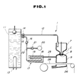
- Reference numeral 1 generally denotes an extraction system according to the present invention.
- a material supplying device 2 is provided to supply a predetermined amount of coffee powder material upon every vending operation.
- Reference character C generally denotes a chamber made of synthetic resin.
- the chamber C is constituted of a funnel 7 and an extracting chamber 9.
- the funnel 7 is provided with an upper opening 4 and a lower opening 5 having a diameter smaller than that of the upper opening 4.
- the funnel 7 has an inclined portion 6 formed between the upper opening 4 and the lower opening 5.
- the extracting chamber 9 is connected at its upper end to the lower opening 5 of the funnel 7.
- a valve 8 is provided to control the communication between the funnel 7 and the extracting chamber 9.
- the powder material supplied from the material supplying device 2 through a shoot 10 is introduced from the upper opening 4 into the funnel 7.
- Hot water is supplied from a hot water tank 11 through a hot water supply pipe 12 into the funnel 7.
- the hot water in the hot water tank 11 is normally heated by a heater 13 to maintain a constant temperature of 90 ° C or more.
- the hot water pipe 12 is connected through an electromagnetic valve 14 to the hot water tank 11.
- the hot water in the hot water tank 11 is also supplied through an electromagnetic valve 15 and a check valve 16 to steam generating means 17.
- the steam generating means 17 includes a heater 18 formed from a block of material having a large heat capacity, such as iron or aluminum. A zigzag passage 19 is formed in the heater 18.
- the heater 18 is normally heated by heat generating means (not shown in Fig. 1) to maintain a constant temperature of 100 ° C or more.
- the steam generating means 17 further includes compressed air supplying means 20 formed from an air compressor.
- the compressed air supplying means 20 is connected through a check valve 21 to a pipe 22 connected between the check valve 16 and an inlet of the passage 19 in the heater 18.
- An outlet of the passage 19 is connected through a steam supply pipe 23 to a steam inlet 24 provided at an upper portion of the extracting chamber 9.
- An extract receptacle 26 is located below the extracting chamber 9, and an annular gasket 27 is embedded in an upper end of the extract receptacle 26 opposed to a lower end of the extracting chamber 9.
- a filter paper 28 is interposed between the extract receptacle 26 and the extracting chamber 9 so as to be movable in the horizontal direction.
- the valve 8 and the chamber C are individually movable in a vertical direction by driving means 30.
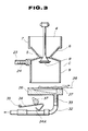
- the valve 8 is controlled to have a first lift position where it is fully closed to seal the lower opening 5, a second lift position where it is closed so as to allow pass of air and steam only as shown in Fig. 1, and a third lift position where it is opened enough to separate from the lower opening 5 as shown in Fig. 3.
- the chamber C is controlled to have a first lift position where it is separate from the filter paper 28 as shown in Fig. 3 and a second lift position where the lower end of the chamber C is in tight contact with the gasket 27 through the filter paper 28.
- the extract receptacle 26 is formed at its lower end with an extract outlet 33 connected to an extract feeding tube 32 for feeding an extracted coffee.
- the feeding tube 32 is formed of silicone rubber.
- An operating member 34 is provided so as to elastically deform the feeding tube 32, thereby controlling opening and closing of the feeding tube 32.
- the operating member 34 is pivotably supported at one end thereof to a shaft 35, and the other end of the operating member 34 is bent to form an operating portion 34A.
- a cam 37 is rotationally provided to effect pivotal movement of the operating member 34 and thereby open or close the feeding tube 32.
- the extract feeding tube 32 is connected at a lower end thereof to a mixing bowl 38 to which sugar and cream are supplied from additional material supplying devices 39 and 40 upon every vending operation.
- a mixing bowl 38 to which sugar and cream are supplied from additional material supplying devices 39 and 40 upon every vending operation.
- the sugar and the cream are mixed with the coffee supplied through the feeding tube 32, and the coffee with the sugar and the cream thus obtained is poured into a coffee cup 41 for vendition.
- the present invention can achieve three kinds of operations, i.e., warmth keeping or heating of the chamber C by steam, steaming of the powder material by steam, and agitation of the mixture of the powder material and the hot water by steam, in addition to the operation to be carried out by the aforementioned prior art extraction system.
- the chamber C of the extraction system 1 is reduced in temperature.
- the valve 8 is operated to fully open the lower opening 5 with the aid of a timer or a sensor for sensing the temperature of the chamber C.
- the electromagnetic valve 15 is opened for a predetermined period of time.
- the hot water in the hot water tank 11 is supplied to the heater 18 of the steam generating means 17.
- the hot water thus supplied is introduced into the passage 19 which has already been heated to a constant temperature of 100 ° C or more, and is instantaneously evaporated to generate a superheated steam in the course of flowing in the passage 19.
- the superheated steam thus generated is blown through the steam supply pipe 23 into the extracting chamber 9.
- the steam blown into the extracting chamber 9 rises to pass through the lower opening 5 into the funnel 7.
- a latent heat is exchanged between the steam and the inner surface of the chamber C to cause an increase in temperature of the inner surface of the chamber C. Accordingly, even when the waiting period is long, the solution in the chamber C is prevented from being cooled.
- the heating of the chamber C can be quickly effected even if the heater 18 has a small capacity, as compared with the case that air only is fed to pass through the heater 18.
- the compressed air supplying means 20 may be operated to blow off a residual water content or solid content in the passage 19.
- the valve 8 is operated from the initial condition shown in Fig. 1 to close the lower opening 5 in such a manner as to permit air and steam only to pass through the lower opening 5.
- the chamber C is lowered to closely contact the extract receptacle 26 through the filter paper 28.
- the powder material is supplied from the material supplying device 2 to fall into the funnel 7.
- the electromagnetic valve 15 is opened for a predetermined period of time to generate steam in the steam generating means 17 and supply the same into the extracting chamber 9. As a result, the steam rises to pass through the lower opening 5 into the funnel 7, thereby steaming the powder material in the funnel 7 from the lower side thereof.
- the powder material in the funnel 7 is steamed by the superheated steam blowing up through the lower opening 5. Accordingly, as compared with the case that a small amount of hot water is poured to the powder material to swell the same as in the prior art, the powder material can be quickly steamed to swell according to the present invention, thereby smoothly effecting the subsequent extraction.
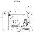
- Fig. 5 steam agitation
- the valve 8 is operated to close the lower opening 5 in such a manner as to permit air and steam only to pass through the lower opening 5, and the chamber C is lowered to closely contact the extract receptacle 26 through the filter paper 28.
- the powder material is supplied from the material supplying device 2 into the funnel 7, and the electromagnetic valve 14 is opened to supply a predetermined amount of hot water from the hot water tank 11 through the hot water supply pipe 12 to the funnel 7, thus obtaining a mixture of the powder material and the hot water.
- the electromagnetic valve 15 is also opened to generate steam in the steam generating means 17 and supply the same into the extracting chamber 9.
- the superheated steam introduced into the extracting chamber 9 rises to pass through the lower opening 5 and then rise in the form of bubbles in the liquid mixture in the funnel 7, thereby agitating the liquid mixture. Accordingly, dissolution of the powder material can be effected quickly by the steam agitation.
- this steam agitation since the bubbles of steam rising in the liquid mixture has a high temperature, the temperature of the liquid mixture can be maintained. Thus, there is no possibility of the temperature of the liquid mixture being lowered by the bubbles.
- compressed air may be supplied from the compressed air supplying means 20 to the extracting chamber 9 simultaneously with the supply of the steam, thereby more smoothly effecting the agitation of the liquid mixture.
- the operating member 34 is maintained to close the extract feeding tube 32.
- the valve 8 After carrying out the steaming and/or the agitation as mentioned above, the valve 8 is lowered to fully open the lower opening 5 and allow the liquid mixture in the funnel 7 to fall into the extracting chamber 9. At this time, the chamber C remains in close contact with the extract receptacle 26 through the filter paper 28. After the liquid mixture falls into the extracting chamber 9, the valve 8 is lifted again to fully close the lower opening 5 as shown in Fig. 6. Then, the compressed air supplying means 20 is operated to supply compressed air from the steam inlet 24 into the extracting chamber 9, thereby pressurizing the inside of the extracting chamber 9. As a result, the liquid mixture now residing in the extracting chamber 9 is forced down by the compressed air, and is filtrated by the filter paper 28 to obtain an extract solution as a coffee drink. At this time, the operating member 34 is operated to open the extract feeding tube 32, thereby feeding the solution through the-mixing bowl 38 to the coffee cup 41.
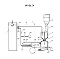
- the chamber C is lifted to separate from the filter paper 28 as shown in Fig. 7.
- the filter paper 28 is horizontally moved a predetermined distance, and a residue of the powder material left on the filter paper 28 is wasted.
- the chamber C and the valve 8 are restored to the initial condition shown in Fig. 1.
- Fig. 8 shows a timing chart of control operation in the case of carrying out the steaming without the agitation.
- the operation is started from the initial condition (e.g., when a select button of an automatic vending machine is depressed by a customer)
- the chamber C is lowered from the initial upper position after a short period of time, and the material supplying device 2 is operated to supply a predetermined amount of powder material into the funnel 7.
- the electromagnetic valve 15 is opened for a predetermined period of time to supply the hot water to the heater 18 and thereby generate a superheated steam.
- the superheated steam is supplied from the steam generating means 17 to the chamber C.
- the valve 8 is in the condition where air and steam only are allowed to pass through the lower opening 5.
- the electromagnetic valve 14 is in a closed condition, and the compressed air supplying means 20 is in a stop condition.
- the above condition of the extraction system 1 is a condition for the steaming.
- the valve 8 is lowered to fully open the lower opening 5, and the electromagnetic valve 14 is opened to supply a predetermined amount of hot water from the hot water tank 11 to the funnel 7.
- the steamed powder material and the hot water are allowed to fall into the extracting chamber 9 (liquid mixture drop period).
- the valve 8 is lifted to fully close the lower opening 5.
- the compressed air supplying means 20 is driven to pressurize the inside of the extracting chamber 9 as blowing a residual water content in the passage 19.
- the liquid mixture in the extracting chamber 9 is forced down to be filtrated by the filter paper 28, thus obtaining an extract solution (extraction period).
- Fig. 9 shows a timing chart of control operation in the case of carrying out the steam agitation without the steaming.
- the chamber C is lowered from the initial upper position after a short period of time, and the material supplying device 2 is operated to supply a predetermined amount of powder material into the funnel 7.
- the electromagnetic valve 15 is opened for a predetermined period of time to supply the hot water to the heater 18 and thereby generate a superheated steam.
- the superheated steam is supplied from the steam generating means 17 to the chamber C.
- the valve 8 is in the condition where air and steam only are allowed to pass through the lower opening 5.
- the electromagnetic valve 14 is also opened to supply a predetermined amount of hot water from the hot water tank 11 to the funnel 7, thus mixing the hot water with the powder material in the funnel 7.
- This condition is a condition for the steam agitation.
- the compressed air supplying means 20 may be driven to supply a compressed air to the chamber C.
- the valve 8 is lowered to fully open the lower opening 5 and thereby drop the liquid mixture into the extracting chamber 9 (liquid mixture drop period).
- the valve 8 When the liquid mixture drop period is terminated, the valve 8 is lifted to fully open the lower opening 5. Then, the compressed air supplying means 20 is driven to pressurize the inside of the extracting chamber 9 as blowing a residual water content in the passage 19. As a result, the liquid mixture in the extracting chamber 9 is forced down to be filtrated by the filter paper 28, thus obtaining an extract solution (extraction period).
- Fig. 10 shows a timing chart of control operation in the case of carrying out both the steaming and the steam agitation.
- the chamber C is lowered from the initial upper position after a short period of time, and the material supplying device 2 is operated to supply a predetermined amount of powder material into the funnel 7.
- the electromagnetic valve 15 is intermittently opened for every predetermined period of time to supply the hot water to the heater 18 and thereby generate a superheated steam.
- the superheated steam is supplied from the steam generating means 17 to the chamber C.
- the valve 8 is in the condition where air and steam only are allowed to pass through the lower opening 5.
- the electromagnetic valve 14 is in a closed condition, and the compressed air supplying means 20 is in a stop condition.
- the steaming of the powder material in the funnel 7 is carried out for a predetermined period of time.
- the electromagnetic valve 14 is also opened to supply a predetermined amount of hot water from the hot water tank 11 to the funnel 7, thus mixing the hot water with the steamed powder material in the funnel 7.
- This condition is a condition for the steam agitation.
- the compressed air supplying means 20 may be driven to supply a compressed air to the chamber C. In this case, since the compressed air to be supplied together with the superheated steam has a relatively high temperature, the agitation of the liquid mixture can be promoted.
- the valve 8 When the period for the steam agitation is terminated, the valve 8 is lowered to fully open the lower opening 5 and thereby drop the liquid mixture into the extracting chamber 9 (liquid mixture drop period). When the liquid mixture drop period is terminated, the valve 8 is lifted to fully close the lower opening 5. Then, the compressed air supplying means 20 is driven to pressurize the inside of the extracting chamber 9 as blowing a residual water content in the passage 19. As a result, the liquid mixture in the extracting chamber 9 is forced down to be filtrated by the filter paper 28, thus obtaining an extract solution (extraction period). At this time, the electromagnetic valve 15 may be opened simultaneously with the driving of the compressed air supplying means 20 to supply steam together with the compressed air into the extracting chamber 9 for the pressure extraction. A series of operation of the extraction system 1 as mentioned above was actually tested to achieve a short operation period of about 35 seconds. Thus, this operation period could be made shorter than that in the conventional method.
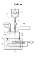
- Fig. 11 shows another preferred embodiment of the steam generating means 17.
- a heater 50 is formed from a block of material having a large heat capacity, such as iron or aluminum, and an electric heater 51 as heat generating means and a thermostat 52 are embedded in the heater 50.
- the electric heater 51 and the thermostat 52 are connected together in series to a power source.
- An outer periphery of the heater 50 except its horizontal upper surface 50A is covered with a heat insulator 53.
- the upper surface 50A of the heater 50 is covered with a detachable transparent plastic cover 54 to define a steam generating chamber 55 therein.
- the plastic cover 54 is formed at its upper end with an inlet pipe 56 which is connected through the electromagnetic valve 15 to the hot water tank 11.
- the plastic cover 54 is further formed at its upper end with an outlet pipe 57 juxtaposed to the inlet pipe 56.
- the outlet pipe 57 is connected to the steam supply pipe 23.
- the heater 50 is heated by the electric heater 51, and the temperature of the heater 50 is normally maintained at 100 ° C or more by the thermostat 52.
- the electromagnetic valve 15 is controlled to be opened or closed by a control device 58 to drop the hot water in the hot water tank 11 onto the upper surface 50A of the heater 50.
- cold water rather than the hot water may be stored in the hot water tank 11.
- the hot water or the cold water having dropped onto the upper surface 50A is instantaneously evaporated to generate steam, which is in turn supplied from the outlet pipe 57 through the steam supply pipe 23 to the chamber C.
- the steam thus supplied is utilized for the steaming of the powder material, the agitation of the liquid mixture, and the pressure extraction of the liquid mixture.
- the following control method may be considered as a method of controlling the electromagnetic valve 15 by the control device 58. That is, since an amount of the hot water or the cold water to be used upon every vending operation is a little and almost constant amount, this amount may be suitably divided to be dropped down to the heater 50 for each function, so as to extract a cup of solution (coffee drink).
- a partial amount of 2 g is used for the steaming of the powder material; a partial amount of 3 g is used for the agitation; and the remaining amount of 5 g is used for the pressure extraction and the blowing in the steam supply pipe 23.
- the steam to be used for the steaming of the powder material and/or the agitation of the liquid mixture is saturated steam
- the saturated steam is readily dewed on a cold inner surface of the chamber C to contract a volume, resulting in a problem that the intended object cannot be achieved. Therefore, the steam to be used must be superheated steam.
- the heater 50 may be expanded as shown in Fig. 12. Referring to Fig. 12, a superheating portion 61 is constructed by forming a passage 60 in the expanded heater 50.
- the passage 60 is connected at one end thereof to the outlet pipe 57 of the plastic cover 54, and the other end of the passage 60 is connected to the steam supply pipe 23. Accordingly, the steam generated in the steam generating chamber 55 is heated again during flowing from the outlet pipe 57 through the superheating portion 61, and it is thereby supplied as a superheated steam to the chamber C.
- Fig. 13 shows a modification of the preferred embodiment shown in Fig. 12, wherein the compressed air supplying means 20 is connected to the steam generating means 17.
- the plastic cover 54 is formed at its upper end with a compressed air inlet pipe 59 juxtaposed to the water inlet pipe 56 on the opposite side of the steam outlet pipe 57, so that the compressed air supplying means 20 is connected to the compressed air inlet pipe 59 of the plastic cover 54.
- compressed air supplied from the compressed air supplying means 20 is used in substitution for the superheated steam or in combination thereof in the case that the agitation or the pressure filtration is not sufficient by the superheated steam only.
- the agitation or the pressure filtration can be further promoted.
- dewed water in the pipe can be blown off by the compressed air.
- Fig. 14 shows another preferred embodiment of the chamber C in the extraction system 1. Unlike the shape of the chamber C shown in Figs. 1 to 3, the chamber C shown in Fig. 14 is generally cylindrical with an expanded upper portion. Further, the valve 8 shown in Figs. 1 to 3 is replaced by a piston-like lid 65 vertically movably provided in the chamber C. A selector valve 66 is provided at the outlet of the passage 19 in the steam generating means 17, and two steam supply pipes 67 and 68 are connected to the selector valve 66. The steam supply pipes 67 and 68 are communicated with the extract receptacle 26 and the chamber C, respectively.
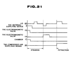
- Fig. 15 illustrates timing control of the steaming, the agitation, and the pressure extraction.
- the chamber C is lowered from the initial upper position after a short period of time to come into close contact with the extract receptacle 26 through the filter paper 28.
- the lid 65 is in an upper position, and the material supplying device 2 is operated to supply a predetermined amount of powder material into the chamber C.
- the electromagnetic valve 15 is opened to supply a hot water to the heater 18 and thereby generate a superheated steam.
- the selector valve 66 is previously in communication with the steam supply pipe 67.
- the superheated steam is supplied from the steam generating means 17 through the steam supply pipe 67 into the extract receptacle 26.
- the superheated steam thus introduced into the extract receptacle 26 rises to pass through the filter paper 28 into the chamber C.
- the electromagnetic valve 14 is in a closed condition, and the compressed air supplying means 20 is in a stop condition. In this way, the steaming of the powder material by the superheated steam is carried out.
- the electromagnetic valve 14 is also opened to supply a predetermined amount of hot water into the chamber C, thereby mixing the hot water with the steamed powder material in the chamber C. In this way, the steam agitation of the liquid mixture is carried out.
- the electromagnetic valve 15 is closed.
- the lid 65 is lowered to sealingly close an upper portion of the chamber C, and the selector valve 66 is operated to communicate with the steam supply pipe 68. Accordingly, the superheated steam is supplied from the steam generating means 17 through the steam supply pipe 68 into the chamber C to thereby pressurize the inside of the chamber C. As a result, the liquid mixture in the chamber C is forced down to be filtrated by the filter paper 28, thus obtaining an extract solution (extraction period).
- Fig. 16 shows a timing chart of control operation in the case of carrying out the steaming of the powder material by steam, the agitation of the liquid mixture by compressed air, and the pressure extraction by compressed air.
- the electromagnetic valve 15 is opened for a predetermined period of time at starting of the operation for the purpose of the steaming only.
- the compressed air supplying means 20 is driven to supply a compressed air to the extract receptacle 26 or the chamber C for the purpose of the agitation or the pressure extraction.
- Fig. 17 shows a modification of the extraction system 1 shown in Fig. 14.
- the selector valve 66 employed in Fig. 14 is eliminated, and two steam supply pipes 70 and 71 are both connected to the chamber C.
- the operation of the extraction system 1 shown in Fig. 17 will now be described with reference to the timing chart shown in Fig. 18.
- Fig. 18 illustrates timing control of the steaming of the powder material, the steam agitation, and the pressure extraction by steam.
- the lid 65 is in an upper position, and the material supplying device 2 is operated to supply a predetermined amount of powder material into the chamber C. Then, the electromagnetic valve 15 is opened to supply hot water to the heater 18 and thereby generate superheated steam. The superheated steam is supplied from the steam generating means 17 through the steam supply pipes 70 and 71 to the chamber C. Accordingly, the steam is blown down against the powder material on the filter paper 28. At this time, the electromagnetic valve 14 is in a closed condition, and the compressed air supplying means 20 is in a stop condition. In this way, the steaming of the powder material by the superheated steam is carried out.
- the electromagnetic valve 14 is also opened to supply a predetermined amount of hot water into the chamber C, thereby mixing the hot water with the steamed powder material in the chamber C.
- a level of the liquid mixture in the chamber C is higher than the outlet of the lower steam supply pipe 71, so that the steam is supplied into the liquid mixture.
- the lid 65 is lowered to sealingly close an upper portion of the chamber C. Accordingly, the liquid mixture in the chamber C is pressurized by the steam introduced from the steam supply pipes 70 and 71, and is forced down to be filtrated by the filter paper 28, thus obtaining an extract solution (extraction period).
- Fig. 19 shows a timing chart of control operation in the case of carrying out the pressure extraction by compressed air in the extraction system 1 shown in Fig. 17.
- the electromagnetic valve 15 is opened for a predetermined period of time at starting of the operation for the purpose of the steaming only, and the agitation is not carried out.
- the compressed air supplying means 20 is driven to supply compressed air into the chamber C for the purpose of the pressure extraction.
- the chamber C is formed with a discharge hole 74, and the steam supply pipe 23 (in this embodiment, a single pipe is provided in the same manner as in Fig. 1) is connected to the chamber C at a position lower than that of the discharge hole 74.
- the lid 65 is in an upper position depicted by P1, so that the upper portion of the chamber C is opened to supply the powder material from the material supplying device 2 into the chamber C.
- the chamber C is lowered to a middle position depicted by P2 which is higher than the position of the discharge hole 74, so that the upper portion of the chamber C is sealingly closed, and the discharge hole 74 opens into the chamber C below the lid 65.
- the electromagnetic valve 15 is opened to supply steam into the chamber C, so as to steam the powder material in the chamber C.
- the lid 65 is lifted again to the position P1 to supply the hot water into the chamber C, thus mixing the hot water with the steamed powder material in the chamber C.
- the lid 65 is lowered to a lower position depicted by P3 which is lower than the position of the discharge hole 74, so that the discharge hole 74 opens to the chamber C above the lid 65.
- the compressed air supplying means 20 is driven to pressurize the liquid mixture in the chamber C, thus effecting the pressure extraction.
- the steam generated from the steam generating means is supplied into the inside of the extraction system as required, thereby increasing a temperature of the inside of the extraction system by a latent heat of the steam. Accordingly, it is possible to prevent the problem that the extraction system is cooled during a waiting period between vending operations, causing cooling of the solution. Thus, a hot and tasty solution such as coffee drink can be provided.
- the powder material prior to mixing of the powder material with the hot water, the powder material can be steamed by using the steam, so that the powder material is swelled to be readily extracted.
- the steam since the steam is used for the steaming of the powder material, the steaming can be effected in a short time as compared with the case where a small amount of hot water is used for the swelling of the powder material. Accordingly, in the case where the extraction system is used in an automatic vending machine, a period of each vending operation can be shortened to become the most effective.
- the liquid mixture of the powder material and the hot water can be agitated by supplying the steam, so that the dissolution of the powder material in the hot water can be promoted, and there is no possibility of the liquid mixture being cooled by the agitation. Accordingly, a reheating device can be eliminated, thereby eliminating a burnt smell of the solution in the prior art and providing a more tasty solution.
- a predetermined amount of steam can be generated by the heating means upon every vending operation, and this steam is used for the extraction of the solution. Accordingly, it is unnecessary to provide a large-scale boiler formed of a pressure resistant vessel for generating steam at all times, thereby suppressing costs and remarkably improving usability in maintenance.
- compressed air is supplied to the steam generating means. Accordingly, a residual water content in the steam generating means can be blown off by the compressed air with the steam, and the liquid mixture can be agitated more effectively by supplying the compressed air in combination with the steam.
Landscapes
- Engineering & Computer Science (AREA)
- Food Science & Technology (AREA)
- Mechanical Engineering (AREA)
- Beverage Vending Machines With Cups, And Gas Or Electricity Vending Machines (AREA)
- Apparatus For Making Beverages (AREA)
- Extraction Or Liquid Replacement (AREA)
- Tea And Coffee (AREA)
Applications Claiming Priority (2)
| Application Number | Priority Date | Filing Date | Title |
|---|---|---|---|
| JP3129965A JP2798818B2 (ja) | 1991-05-31 | 1991-05-31 | 抽出装置 |
| JP129965/91 | 1991-05-31 |
Publications (3)
| Publication Number | Publication Date |
|---|---|
| EP0516884A2 true EP0516884A2 (fr) | 1992-12-09 |
| EP0516884A3 EP0516884A3 (en) | 1993-04-07 |
| EP0516884B1 EP0516884B1 (fr) | 1995-08-16 |
Family
ID=15022811
Family Applications (1)
| Application Number | Title | Priority Date | Filing Date |
|---|---|---|---|
| EP91121490A Expired - Lifetime EP0516884B1 (fr) | 1991-05-31 | 1991-12-14 | Système d'extraction |
Country Status (5)
| Country | Link |
|---|---|
| EP (1) | EP0516884B1 (fr) |
| JP (1) | JP2798818B2 (fr) |
| KR (1) | KR960001210B1 (fr) |
| DE (1) | DE69112203D1 (fr) |
| MY (1) | MY106903A (fr) |
Cited By (5)
| Publication number | Priority date | Publication date | Assignee | Title |
|---|---|---|---|---|
| US5937738A (en) * | 1996-06-11 | 1999-08-17 | Sanden Corporation | Coffee extracting apparatus for extracting coffee essence with use of compressed air stored in an accumulator |
| US7240610B2 (en) * | 2004-03-10 | 2007-07-10 | Ihc Invest, Inc. | Method and apparatus for infusing a liquid with a flavoring or a scent |
| NL2006357C2 (nl) * | 2011-03-08 | 2012-09-11 | Bravilor Holding Bv | Inrichting voor het bereiden van een warme drank. |
| GB2624645A (en) * | 2022-11-23 | 2024-05-29 | Karl And Son Ltd | Coffee machine |
| US12161246B2 (en) | 2020-04-09 | 2024-12-10 | Keurig Green Mountain, Inc. | Air preheating of brew chamber |
Families Citing this family (11)
| Publication number | Priority date | Publication date | Assignee | Title |
|---|---|---|---|---|
| ITFI20060244A1 (it) * | 2006-10-04 | 2008-04-05 | Saeco Ipr Ltd | Macchina per la produzione di caffe' o simili e relativo metodo |
| GB2449630B (en) * | 2007-05-18 | 2010-01-06 | Kraft Foods R & D Inc | Beverage preparation machines and methods for operating beverage preparation machines |
| KR100796017B1 (ko) * | 2007-06-20 | 2008-01-21 | 매일유업주식회사 | 에스프레소 커피추출 방법 |
| KR200473999Y1 (ko) * | 2014-03-07 | 2014-08-14 | 이용재 | 혼합 장치 |
| EP3536158B1 (fr) | 2017-08-07 | 2023-05-17 | Daito Giken, Inc. | Procédé d'extraction et dispositif d'extraction |
| IT201800001717A1 (it) * | 2018-01-24 | 2019-07-24 | De Longhi Appliances Srl | Dispositivo per il riscaldamento e l’emulsione di bevande |
| JP6644283B1 (ja) * | 2018-09-25 | 2020-02-12 | 株式会社Tree Field | 飲料製造装置およびその制御方法 |
| JP6644284B1 (ja) * | 2018-09-25 | 2020-02-12 | 株式会社Tree Field | 飲料製造装置および飲料送出方法 |
| JP7219971B2 (ja) * | 2019-12-16 | 2023-02-09 | 株式会社大都技研 | 飲料製造装置 |
| JP7173573B2 (ja) * | 2019-12-16 | 2022-11-16 | 株式会社大都技研 | 飲料製造装置および飲料送出方法 |
| KR102574363B1 (ko) * | 2020-11-24 | 2023-09-04 | 한국해양바이오클러스터 주식회사 | 함초 추출물의 제조 방법 및 이에 의해 제조된 함초 추출물 |
Family Cites Families (6)
| Publication number | Priority date | Publication date | Assignee | Title |
|---|---|---|---|---|
| DE2952556A1 (de) * | 1979-12-28 | 1981-07-09 | Bosch-Siemens Hausgeräte GmbH, 7000 Stuttgart | Elektrische kaffeemaschine |
| NL8400116A (nl) * | 1984-01-13 | 1985-08-01 | Philips Nv | Espresso-apparaat. |
| JPS6131108A (ja) * | 1984-07-23 | 1986-02-13 | 三洋電機株式会社 | 抽出装置 |
| JPS61159925A (ja) * | 1985-01-09 | 1986-07-19 | 三洋電機株式会社 | 飲料抽出装置 |
| EP0217211A3 (fr) * | 1985-09-23 | 1987-10-21 | ESSEGIELLE S.r.l | Machine à café |
| JPH03198821A (ja) * | 1989-12-26 | 1991-08-30 | Yamaoka Kinzoku Kogyo Kk | 飲料抽出装置 |
-
1991
- 1991-05-31 JP JP3129965A patent/JP2798818B2/ja not_active Expired - Fee Related
- 1991-10-23 KR KR1019910018636A patent/KR960001210B1/ko not_active Expired - Fee Related
- 1991-12-14 EP EP91121490A patent/EP0516884B1/fr not_active Expired - Lifetime
- 1991-12-14 DE DE69112203T patent/DE69112203D1/de not_active Expired - Lifetime
- 1991-12-20 MY MYPI91002367A patent/MY106903A/en unknown
Cited By (7)
| Publication number | Priority date | Publication date | Assignee | Title |
|---|---|---|---|---|
| US5937738A (en) * | 1996-06-11 | 1999-08-17 | Sanden Corporation | Coffee extracting apparatus for extracting coffee essence with use of compressed air stored in an accumulator |
| US7240610B2 (en) * | 2004-03-10 | 2007-07-10 | Ihc Invest, Inc. | Method and apparatus for infusing a liquid with a flavoring or a scent |
| NL2006357C2 (nl) * | 2011-03-08 | 2012-09-11 | Bravilor Holding Bv | Inrichting voor het bereiden van een warme drank. |
| EP2497394A1 (fr) * | 2011-03-08 | 2012-09-12 | Bravilor Holding B.V. | Dispositif pour préparer des boissons chaudes |
| US9113748B2 (en) | 2011-03-08 | 2015-08-25 | Bravilor Holding B.V. | Device for preparing a hot beverage |
| US12161246B2 (en) | 2020-04-09 | 2024-12-10 | Keurig Green Mountain, Inc. | Air preheating of brew chamber |
| GB2624645A (en) * | 2022-11-23 | 2024-05-29 | Karl And Son Ltd | Coffee machine |
Also Published As
| Publication number | Publication date |
|---|---|
| EP0516884B1 (fr) | 1995-08-16 |
| JP2798818B2 (ja) | 1998-09-17 |
| KR920021102A (ko) | 1992-12-18 |
| KR960001210B1 (ko) | 1996-01-24 |
| JPH04354912A (ja) | 1992-12-09 |
| DE69112203D1 (de) | 1995-09-21 |
| EP0516884A3 (en) | 1993-04-07 |
| MY106903A (en) | 1995-08-30 |
Similar Documents
| Publication | Publication Date | Title |
|---|---|---|
| EP0516884B1 (fr) | Système d'extraction | |
| US3443508A (en) | Automatic beverage brewer | |
| CA1254395A (fr) | Percolateur pour le cafe | |
| US4633771A (en) | Coffee percolator | |
| US4134332A (en) | Continuous beverage brewer | |
| US2890643A (en) | Beverage brewing and dispensing apparatus | |
| US2638839A (en) | Beverage urn | |
| JP2976598B2 (ja) | 飲料抽出装置 | |
| US2660947A (en) | Beverage brewing machine | |
| GB1185470A (en) | Improvements in or relating to Apparatus for Making Coffee or Other Beverages. | |
| EP3733032A1 (fr) | Machine à café automatique | |
| JPH08112204A (ja) | 自動販売機の飲料抽出装置 | |
| JP2005192801A (ja) | 飲料抽出装置 | |
| JP2005004611A (ja) | 飲料抽出装置 | |
| JP2736203B2 (ja) | 自動販売機における抽出濾過方法 | |
| JPH05237035A (ja) | 飲料抽出装置 | |
| JPH05197878A (ja) | 飲料抽出装置 | |
| KR0167195B1 (ko) | 원두커피판매용 자동판매기 및 그 원두커피액 제조공급 제어방법 | |
| JPH0685740B2 (ja) | 電気コ−ヒ−沸し器 | |
| JP4033064B2 (ja) | 飲料抽出装置 | |
| GB1583877A (en) | Coffee brewer with means for dispensing controlled quantities of hot water | |
| JPH0687277B2 (ja) | 自動販売機のコ−ヒ抽出濾過方法 | |
| KR940020992A (ko) | 원심분리형 한약추출기의 약물추출회로 및 추출제어방법 | |
| JPH01158592A (ja) | 飲料抽出装置 | |
| JPS6282921A (ja) | 電気コ−ヒ−沸し器 |
Legal Events
| Date | Code | Title | Description |
|---|---|---|---|
| PUAI | Public reference made under article 153(3) epc to a published international application that has entered the european phase |
Free format text: ORIGINAL CODE: 0009012 |
|
| AK | Designated contracting states |
Kind code of ref document: A2 Designated state(s): DE FR GB IT |
|
| PUAL | Search report despatched |
Free format text: ORIGINAL CODE: 0009013 |
|
| AK | Designated contracting states |
Kind code of ref document: A3 Designated state(s): DE FR GB IT |
|
| 17P | Request for examination filed |
Effective date: 19930703 |
|
| 17Q | First examination report despatched |
Effective date: 19940525 |
|
| GRAA | (expected) grant |
Free format text: ORIGINAL CODE: 0009210 |
|
| AK | Designated contracting states |
Kind code of ref document: B1 Designated state(s): DE FR GB IT |
|
| PG25 | Lapsed in a contracting state [announced via postgrant information from national office to epo] |
Ref country code: FR Free format text: THE PATENT HAS BEEN ANNULLED BY A DECISION OF A NATIONAL AUTHORITY Effective date: 19950816 |
|
| REF | Corresponds to: |
Ref document number: 69112203 Country of ref document: DE Date of ref document: 19950921 |
|
| ITF | It: translation for a ep patent filed | ||
| PG25 | Lapsed in a contracting state [announced via postgrant information from national office to epo] |
Ref country code: DE Effective date: 19951117 |
|
| PG25 | Lapsed in a contracting state [announced via postgrant information from national office to epo] |
Ref country code: GB Effective date: 19951214 |
|
| EN | Fr: translation not filed | ||
| PLBE | No opposition filed within time limit |
Free format text: ORIGINAL CODE: 0009261 |
|
| STAA | Information on the status of an ep patent application or granted ep patent |
Free format text: STATUS: NO OPPOSITION FILED WITHIN TIME LIMIT |
|
| 26N | No opposition filed | ||
| GBPC | Gb: european patent ceased through non-payment of renewal fee |
Effective date: 19951214 |
|
| PGFP | Annual fee paid to national office [announced via postgrant information from national office to epo] |
Ref country code: IT Payment date: 20061231 Year of fee payment: 16 |
|
| PG25 | Lapsed in a contracting state [announced via postgrant information from national office to epo] |
Ref country code: IT Free format text: LAPSE BECAUSE OF NON-PAYMENT OF DUE FEES Effective date: 20071214 |