EP0516927A2 - Système de code à bâtonnets - Google Patents
Système de code à bâtonnets Download PDFInfo
- Publication number
- EP0516927A2 EP0516927A2 EP92104632A EP92104632A EP0516927A2 EP 0516927 A2 EP0516927 A2 EP 0516927A2 EP 92104632 A EP92104632 A EP 92104632A EP 92104632 A EP92104632 A EP 92104632A EP 0516927 A2 EP0516927 A2 EP 0516927A2
- Authority
- EP
- European Patent Office
- Prior art keywords
- bar code
- code system
- scanning beam
- beam generating
- generating device
- Prior art date
- Legal status (The legal status is an assumption and is not a legal conclusion. Google has not performed a legal analysis and makes no representation as to the accuracy of the status listed.)
- Granted
Links
Images


Classifications
-
- G—PHYSICS
- G06—COMPUTING OR CALCULATING; COUNTING
- G06K—GRAPHICAL DATA READING; PRESENTATION OF DATA; RECORD CARRIERS; HANDLING RECORD CARRIERS
- G06K7/00—Methods or arrangements for sensing record carriers, e.g. for reading patterns
- G06K7/10—Methods or arrangements for sensing record carriers, e.g. for reading patterns by electromagnetic radiation, e.g. optical sensing; by corpuscular radiation
- G06K7/12—Methods or arrangements for sensing record carriers, e.g. for reading patterns by electromagnetic radiation, e.g. optical sensing; by corpuscular radiation using a selected wavelength, e.g. to sense red marks and ignore blue marks
Definitions
- the invention relates to a bar code system with bar codes located on a background and with a bar code reading device which has a scanning beam generating device and reading means for reading the respective bar code, the information content of which is formed by bars and / or gaps of different widths.
- Bar code reading systems or reading devices are known in different designs.
- US Pat. No. 4,093,865 discloses a stationary bar code reading system.
- Manually portable bar code reading systems are also commercially available.
- the known bar code reading devices have in common that they can read bar codes attached to goods or the like.
- a scanning beam is guided by a scanning beam generating device over the bar code and the scanning result is picked up by reading means which carry out an evaluation.
- the bar codes used in practice consist of a series of parallel ones arranged side by side Strokes of constant or different widths and gaps between them also constant or different widths.
- the wavelength of the scanning beam is generally in the visible spectral range; however, it is also entirely possible to choose a wavelength that is in the infrared range.
- bar codes are read which are represented by black lines on a white background in the classic sense.
- color combinations defined by the EAN system which can be detected on the basis of red light or infrared reading devices. Other color combinations cannot be detected with the known reading devices.
- the invention is therefore based on the object of providing a bar code reading device of the type mentioned at the outset which can detect bar codes with a special bar color or with special bar colors on a selectable background color or selectable background colors.
- Multicolored are also preferred Bar codes, in particular multicolored bar colors and / or multicolored background colors, legible.
- the scanning beam generating device emits radiation of different wavelengths at the same time or in succession in order to recognize the color-selectable lines or gaps on the color-selectable background.
- the wavelength of the scanning beams is matched to the color combination of bar color or bar colors of the bar code and background color or background color.
- the bar code is integrated into the product in a quasi-color manner and remains legible due to the invention. Moreover, because of the configuration according to the invention, it is no longer necessary to use a further printing color (for example black) for the bar code, since the color of the other printing can also be used for the bar code. This represents a significant cost saving in the area of the packaging sector. It should also be pointed out that the code information is provided by the widths of the code bars or gaps between the bars, but not by the color of the code.
- the scanning beam generating device may have a plurality of sources of different wavelengths which emit radiation cyclically in succession.
- the scanning beam generating device has only one source, which is, however, able to transmit different wavelengths cyclically one after the other. It is then a so-called “tunable source”.
- a source is always to be understood as a light source, the light of which can be in the visible as well as in the infrared range.
- the scanning beam generating device has a deflection device for guiding the beams of the transmitted scanning beams. This deflection device oscillates so that the scanning beams sweep over a reading area.
- the bar code reading device has a receiver which belongs to the reading means and serves the reading process of the radiation reflected by the bar code and the background.
- the deflection device can preferably be designed as an oscillating deflection mirror.
- the mirror is provided with a corresponding drive for the oscillation movement.
- a mirrored, rotating polygon roller as the deflection device.
- the individual flat lateral surfaces of this polygon roller when rotated, effect a corresponding beam guidance of the scanning beams, so that a certain reading area in which the bar code is located is detected.
- a sensor is arranged in the beam path, which detects the oscillation interval of the deflection device and changes the wavelength of the scanning beam generating device after at least one oscillation interval.
- a scanning beam with a changing wavelength is continuously emitted after the expiry of one or a preselectable number of oscillation intervals.
- different scanning beam generating devices each with an associated wavelength, can be activated in succession, or their frequency and thus the wavelength of the scanning beam emitted by the same scanning beam generating device are changed.
- it is a so-called tunable source, in which a new tuning to a different wavelength takes place after each or several preselectable oscillation intervals.
- the scanning beam generating device can be designed as a laser arrangement.
- the scanning beam generating device is connected to at least one optical waveguide (LWL) with which the radiation of different wavelengths is guided into the immediate vicinity of the bar code.
- This optical fiber is an outgoing conductor, the means that it transports the scanning radiation to the bar code.
- the radiation reflected by the bar code is fed to the receiver by means of at least one further optical waveguide.
- This further optical waveguide thus serves as a return conductor.
- Forward and return conductors can be formed in particular by fiber optic cables.
- a deflection device for example a rotating deflection mirror
- the radiation is sent via the optical waveguide in the immediate vicinity of the bar code, hits the bar code there and is reflected accordingly and is detected by the optical waveguide serving as a return conductor and fed to the receiver.
- This arrangement naturally presupposes that the bar code-side ends of the optical waveguides (forward and return conductors) and the bar code perform a relative movement to one another, so that all bars or gaps in the bar code can be detected. This can be done by moving the optical fiber relative to the bar code or the bar code relative to the optical fibers. A combinatorial movement is also conceivable, that is to say both the optical waveguide and the bar code move.
- the scanning beam generating device is a white light source coupled to the optical waveguide (outgoing conductor).
- optical waveguides which serve as outgoing conductors and which are coupled to radiation sources having mutually different wavelengths, each of these optical waveguides being assigned to one of the radiation sources of the scanning beam generating device.
- the radiation sources can be light-emitting diodes of different colors or lasers of different colors.
- the optical waveguides assigned to one another and serving as outgoing and return conductors are combined as a pair of optical waveguides running spatially close to one another.
- This spatially dense combination certainly only needs in the area of the bar code-side ends of the optical waveguide of the associated Optical fiber pair apply, since it is then ensured that the radiation supplied by the outgoing conductor and reflected by the bar code is reliably readable by the return conductor.
- the individual pairs of optical fibers can be combined as a bundle.
- the individual pairs of optical fibers are arranged distributed over the detection area of the bar code.
- An amplifier is preferably connected to the receiver end of each optical waveguide serving as a return conductor, so that the received signals can be amplified.
- the optical waveguides serving as return conductors can lead to a logic logic circuit with which the received signals (reflected radiation) or else the received signals amplified by the amplifiers can be logically linked, in particular "logically and" and / or "logically or”.
- the output of this logic logic circuit is connected to a decoder, which evaluates the pulse train received.
- the ends of the optical waveguide on the bar code side are assigned a transmitting / reading optical system.
- FIG. 1 shows a schematic representation of a bar code reading device 1 which is used to detect a bar code 2 which is located on a background 3.
- the lines 4 indicate the limits of the reading range of the bar code reading device 1.
- a plurality of scanning beam generating devices 6, 6 'etc. are accommodated, which throw the radiation generated by them onto a deflection device 7, which deflect the scanning beams and fan them out across the width of the detection area / reading area.
- a deflection device 7 which deflect the scanning beams and fan them out across the width of the detection area / reading area.
- FIG 1 only two scanning beam generating devices 6 and 6 'are shown. However, the invention is not limited to this; further scanning beam generating devices can be provided.
- Each scanning beam generating device 6 or 6 'etc. differs from another scanning beam generating device by the wavelength of the emitted scanning beams, so that the bar code 2 is simultaneously or successively exposed to a plurality of different wavelengths of scanning beams.
- the deflection device 7 has a deflection mirror 8 which is provided with a drive 9 for an oscillatory movement. Due to the oscillating movement of the deflection mirror 8, each scanning beam is fanned out in accordance with the reading area delimited by the lines 4.
- the fan beams preferably pass through an optical system 10.
- the radiation reflected by the bar code 2 and the background 3 is detected by a receiver 11, which feeds the received signal to a decoder 13 via a pulse shaper stage 12.
- An interface 14, which leads to an evaluation unit 15, is connected to the output of the decoder 13.
- the evaluation unit 15 analyzes the information content of the bar code 2.
- the individual scanning beam generating devices 6, 6 'etc. each emit a different wavelength, it is possible to detect corresponding bar code colors and / or background colors, so that codes with corresponding colors and / or codes of different colors are available due to the large number of available wavelengths are detectable.
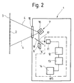
- FIG. 2 shows a further embodiment, which largely corresponds to the embodiment of FIG. 2. Only the differences from the exemplary embodiment in FIG. 1 will be discussed here. These differences are that instead of the oscillating deflecting mirror 8, a mirrored, rotating polygon roller 16 is provided. Furthermore, the bundled scanning beams coming from the scanning beam generating devices 6, 6 'etc. pass through openings 17 of a mirror 18 which is arranged between the individual scanning beam generating devices 6, 6' and the polygon roller 16. It serves the reflected radiation coming from the polygon roller 16 to redirect them to the receiver 11.
- FIG. 3 shows a further exemplary embodiment, which differs from that of FIG. 1 in that only one scanning beam generating device 6 is provided, which is controlled by a sensor 19.
- the sensor 19 registers the oscillation interval of the deflection device 7 and, after one or a predeterminable number of oscillation intervals, causes the wavelength of the emitted radiation of the scanning beam generating device 6 to change.
- This exemplary embodiment is therefore a tunable source, that is to say that the wavelength of the emitted radiation can be changed stepwise or continuously by appropriate control. In this respect, it is possible to detect corresponding bar code colors or background colors of bar code 2.
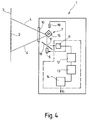
- FIG. 4 shows a last exemplary embodiment of a barcode reading device according to the invention, which differs from the exemplary embodiment in FIG. 2 in that it also has a sensor 19 in order to control the tunable scanning beam generating device 6 in the rhythm of the oscillation interval to emit different wavelengths can.
- the lines have a greater degree of absorption of the radiation compared to the gaps.
- an inverse code display is also conceivable, in which the lines have a lower absorption capacity than the gaps.
- both variants are suitable for capturing the bar code.
- the bar code reading device can be designed as a compact device or else as a plurality of separate structural units which are connected to one another by cables. It can be designed as a stationary arrangement or else as a manually portable arrangement. In the latter case, it is possible to provide a manually portable reading head, which may also contain the evaluation circuit and which can be connected to a stationary unit via an electrical cable.
- a receiver In the case of a tunable scanning beam generating device, a receiver is used which, on the one hand, has the spectral sensitivity of the variation of the tunable transmitter or, on the other hand, enables the switching of a receiving element in connection with the synchronization of the tuning to the respective sensitivity (wavelength).
- the scanning beam generating device with its deflection unit can also be used according to the invention trained omni-directional scanner.
- Figure 5 shows schematically a reading method of a bar code 2, which works on the principle of "ladder arrangement" (ladder).
- the bar code reading device for example designed according to the exemplary embodiment in FIG. 1, guides the scanning beam 20 transversely to the bar profile of the bar code 2, the object 21 carrying the bar code 2 moving in the direction of the longitudinal extent of the bars of the bar code 2.
- FIG. 6 illustrates another principle that is referred to as a "picket fence". While the beam guidance in the embodiment of FIG. 5 takes place transversely to the direction of movement of the object 21, in the embodiment of FIG. 6- the direction of movement of the scanning beam 20 coincides with the movement of the object 21. The direction of movement of the object 21 is indicated by an arrow 22.
- the scanning corresponds approximately to that in the exemplary embodiment in FIG. 6, but a special bar code reading device 1 is used which does not fan out the scanning beam by means of a steering device, so that a corresponding area delimited by the lines 4 is cyclically swept , but an optical waveguide 23 is provided which receives the radiation originating from a white light radiation source up to the immediate vicinity of the bar code 2 leads.
- the radiation of different wavelengths emerges from the end 24 of the optical waveguide 23 on the bar code side and strikes the bar code 2.
- the reflected radiation reaches another optical waveguide 25 and is fed by the latter to the scanning beam receiving device 1 for reading.
- the optical waveguide 23 serves as an outgoing conductor and the optical waveguide 25 as a return conductor.
- the condition for reading the bar code 2 is that there is a relative movement between the end 24 and the end 26 of the optical fibers 23 and 25 relative to the bar code 2, so that all lines and gaps in the code can be detected. According to the exemplary embodiment in FIG. 7, this is given by the fact that the object 21 carrying the bar code 2 travels under the ends 24 and 26 of the optical waveguides 23 and 25. According to another embodiment, not shown, it is also conceivable that the optical fiber ends 24 and 26 are moved relative to the bar code 2 over this.
- FIGS. 8 and 9 show configurations of the exemplary embodiment in FIG. 7. It can be seen that a white light radiation source 27 guides radiation of different wavelengths to the object 21 carrying the bar code 2 via the optical waveguide 23.
- the optical waveguide 23 forms an outgoing conductor, which with the return conductor (Optical fiber 25) is combined to form a pair of optical fibers 28 running closely next to each other.
- a transmission / reading optic 29 is arranged, which is used for beam bundling and thus the optimal transmission and reading behavior.
- This transmission / reading optics 29 can be designed jointly or separately for the two optical fibers 23 and 25.
- the radiation reflected by the object 21 is fed via the optical waveguide 25 to an optical receiving system 30 (receiver 11) which preferably has one or more radiation-sensitive photodiodes or the like.
- the receiving optics 30 is connected to an amplifier 31, which amplifies the received signal and feeds it to a decoder 32, which carries out the evaluation of the bar code information.
- the exemplary embodiment in FIG. 9 shows a structure similar to that which is already known from FIG. 8, but not a single white light radiation source is provided, but rather a plurality of radiation sources 33 - of which three are shown by way of example in FIG. 9 - the radiation emit different wavelength.
- the radiation sources 33 can be light-emitting diodes of different colors or lasers of different colors.
- the radiation is supplied to the object 21 carrying the bar code 2 via corresponding optical waveguides 23 assigned to each radiation source 33.
- everyone as a leader serving optical waveguide 23 is assigned an optical waveguide 25 serving as a return conductor, an outgoing conductor and a return conductor each forming a pair of optical waveguides 28.
- the individual optical fiber pairs 28 are combined as a bundle 34, which has a transmitting / reading optic 29 at its bar code-side end 35.
- the receiving end of each optical waveguide 25 (return conductor) is assigned a respective receiving optic 30 which has a photoelectric element which corresponds in its respective radiation sensitivity to the light wavelength range or the light wavelength which is emitted by the respectively associated radiation source 33.
- the individual receiving optics 30 are connected to amplifiers 31, the outputs of which are connected to a logic logic circuit 36.
- This logic logic circuit 36 has selectively usable AND gates and / or OR gates, so that the respective received signals can be logically linked to one another.
- the output of the logic logic circuit 36 is connected to a decoder 32, which carries out the evaluation of the received signals.
Landscapes
- Physics & Mathematics (AREA)
- Engineering & Computer Science (AREA)
- Health & Medical Sciences (AREA)
- Electromagnetism (AREA)
- General Health & Medical Sciences (AREA)
- Toxicology (AREA)
- Artificial Intelligence (AREA)
- Computer Vision & Pattern Recognition (AREA)
- General Physics & Mathematics (AREA)
- Theoretical Computer Science (AREA)
- Cash Registers Or Receiving Machines (AREA)
- Mechanical Optical Scanning Systems (AREA)
Applications Claiming Priority (2)
| Application Number | Priority Date | Filing Date | Title |
|---|---|---|---|
| DE4108916 | 1991-03-19 | ||
| DE4108916A DE4108916C2 (de) | 1991-03-19 | 1991-03-19 | Strichcode-System |
Publications (3)
| Publication Number | Publication Date |
|---|---|
| EP0516927A2 true EP0516927A2 (fr) | 1992-12-09 |
| EP0516927A3 EP0516927A3 (en) | 1993-03-03 |
| EP0516927B1 EP0516927B1 (fr) | 1995-09-13 |
Family
ID=6427650
Family Applications (1)
| Application Number | Title | Priority Date | Filing Date |
|---|---|---|---|
| EP92104632A Expired - Lifetime EP0516927B1 (fr) | 1991-03-19 | 1992-03-18 | Système de code à bâtonnets |
Country Status (2)
| Country | Link |
|---|---|
| EP (1) | EP0516927B1 (fr) |
| DE (2) | DE4108916C2 (fr) |
Cited By (12)
| Publication number | Priority date | Publication date | Assignee | Title |
|---|---|---|---|---|
| EP0727753A1 (fr) * | 1995-01-20 | 1996-08-21 | Toppan Printing Co., Ltd. | Support d'enregistrement d'information |
| GB2302435B (en) * | 1995-06-21 | 1998-12-16 | Asahi Optical Co Ltd | Data symbol reading device |
| WO2002073953A3 (fr) * | 2001-03-08 | 2003-04-03 | Hand Held Prod Inc | Module d'imagerie de lecteur optique |
| US6601768B2 (en) | 2001-03-08 | 2003-08-05 | Welch Allyn Data Collection, Inc. | Imaging module for optical reader comprising refractive diffuser |
| US6832725B2 (en) | 1999-10-04 | 2004-12-21 | Hand Held Products, Inc. | Optical reader comprising multiple color illumination |
| WO2005008565A1 (fr) * | 2003-07-17 | 2005-01-27 | Symbol Technologies, Inc. | Systeme et procede de lecture et de decodage de codes optiques par eclairement multicolore |
| US7270274B2 (en) | 1999-10-04 | 2007-09-18 | Hand Held Products, Inc. | Imaging module comprising support post for optical reader |
| US7296751B2 (en) | 1999-10-04 | 2007-11-20 | Hand Held Products, Inc. | Imaging module for optical reader |
| US7965887B2 (en) | 2005-12-01 | 2011-06-21 | Cognex Technology And Investment Corp. | Method of pattern location using color image data |
| US8061610B2 (en) | 2005-10-24 | 2011-11-22 | Cognex Technology And Investment Corporation | System and method for employing color illumination and color filtration in a symbology reader |
| US8152069B2 (en) | 2007-12-28 | 2012-04-10 | Metrologic Instruments, Inc. | Dual focus imaging based symbology reading system |
| US9224023B2 (en) | 2002-06-04 | 2015-12-29 | Hand Held Products, Inc. | Apparatus operative for capture of image data |
Families Citing this family (2)
| Publication number | Priority date | Publication date | Assignee | Title |
|---|---|---|---|---|
| DE4319555A1 (de) * | 1993-06-13 | 1994-12-15 | Tetra Pak Aps Gmbh | Markierung in Form von Farbzeichen |
| DE29505165U1 (de) * | 1995-03-27 | 1995-05-18 | Erwin Sick Gmbh Optik-Elektronik, 79183 Waldkirch | Farbsensoranordnung zum Lesen farbiger Markierungen |
Family Cites Families (10)
| Publication number | Priority date | Publication date | Assignee | Title |
|---|---|---|---|---|
| US3812325A (en) * | 1970-08-18 | 1974-05-21 | Chesapeake & Ohio Railway | Means for reading and interpreting color-coded identification labels |
| US3684868A (en) * | 1970-10-29 | 1972-08-15 | Ncr Co | Color bar code tag reader with light-emitting diodes |
| DE2214386C3 (de) * | 1972-03-24 | 1978-10-26 | Erwin Sick Gmbh Optik-Elektronik, 7808 Waldkirch | Verfahren zum Lesen streifenförmiger Informationsträger |
| DE2713396A1 (de) * | 1977-03-24 | 1978-09-28 | Applied Photophysics Ltd | Verfahren und vorrichtung zur kennzeichnung oder identifizierung eines leuchtmaterial enthaltenden oder tragenden koerpers |
| US4093865A (en) * | 1977-04-29 | 1978-06-06 | National Semiconductor Corporation | Code symbol scanner using a double X bar pattern |
| EP0101939B1 (fr) * | 1982-07-29 | 1989-03-22 | Nippondenso Co., Ltd. | Appareil pour la lecture optique d'information |
| DE3311352C1 (de) * | 1983-03-29 | 1984-03-15 | Ingenieurbüro Rudolf Weber KG, 6100 Darmstadt | Detektor zur Registrierung von Marken |
| JPH01292485A (ja) * | 1988-05-19 | 1989-11-24 | Pioneer Electron Corp | 多重印刷バーコード方式 |
| DE3817402A1 (de) * | 1988-05-21 | 1989-11-30 | Messerschmitt Boelkow Blohm | Optisches kodierverfahren sowie zugehoeriges ausleseverfahren |
| WO1990016043A1 (fr) * | 1989-06-19 | 1990-12-27 | Lansco Inc | Appareil d'authentification utilisant l'absorption de lumiere par resonnance |
-
1991
- 1991-03-19 DE DE4108916A patent/DE4108916C2/de not_active Expired - Fee Related
-
1992
- 1992-03-18 DE DE59203633T patent/DE59203633D1/de not_active Expired - Fee Related
- 1992-03-18 EP EP92104632A patent/EP0516927B1/fr not_active Expired - Lifetime
Cited By (16)
| Publication number | Priority date | Publication date | Assignee | Title |
|---|---|---|---|---|
| US5760384A (en) * | 1995-01-20 | 1998-06-02 | Toppan Printing Co., Ltd. | Information storage medium and method for detecting forgeries |
| USRE37491E1 (en) | 1995-01-20 | 2002-01-01 | Toppan Printing Co., Ltd. | Information storage medium and method for detecting forgeries |
| EP0727753A1 (fr) * | 1995-01-20 | 1996-08-21 | Toppan Printing Co., Ltd. | Support d'enregistrement d'information |
| GB2302435B (en) * | 1995-06-21 | 1998-12-16 | Asahi Optical Co Ltd | Data symbol reading device |
| US5877487A (en) * | 1995-06-21 | 1999-03-02 | Asahi Kogaku Kogyo Kabushiki Kaisha | Data symbol reading device |
| US7296751B2 (en) | 1999-10-04 | 2007-11-20 | Hand Held Products, Inc. | Imaging module for optical reader |
| US6832725B2 (en) | 1999-10-04 | 2004-12-21 | Hand Held Products, Inc. | Optical reader comprising multiple color illumination |
| US7270274B2 (en) | 1999-10-04 | 2007-09-18 | Hand Held Products, Inc. | Imaging module comprising support post for optical reader |
| WO2002073953A3 (fr) * | 2001-03-08 | 2003-04-03 | Hand Held Prod Inc | Module d'imagerie de lecteur optique |
| US6601768B2 (en) | 2001-03-08 | 2003-08-05 | Welch Allyn Data Collection, Inc. | Imaging module for optical reader comprising refractive diffuser |
| US9224023B2 (en) | 2002-06-04 | 2015-12-29 | Hand Held Products, Inc. | Apparatus operative for capture of image data |
| WO2005008565A1 (fr) * | 2003-07-17 | 2005-01-27 | Symbol Technologies, Inc. | Systeme et procede de lecture et de decodage de codes optiques par eclairement multicolore |
| US7028901B2 (en) | 2003-07-17 | 2006-04-18 | Symbol Technologies, Inc. | System and method for reading and decoding optical codes using multiple color illumination |
| US8061610B2 (en) | 2005-10-24 | 2011-11-22 | Cognex Technology And Investment Corporation | System and method for employing color illumination and color filtration in a symbology reader |
| US7965887B2 (en) | 2005-12-01 | 2011-06-21 | Cognex Technology And Investment Corp. | Method of pattern location using color image data |
| US8152069B2 (en) | 2007-12-28 | 2012-04-10 | Metrologic Instruments, Inc. | Dual focus imaging based symbology reading system |
Also Published As
| Publication number | Publication date |
|---|---|
| DE59203633D1 (de) | 1995-10-19 |
| EP0516927B1 (fr) | 1995-09-13 |
| DE4108916C2 (de) | 1994-11-17 |
| EP0516927A3 (en) | 1993-03-03 |
| DE4108916A1 (de) | 1992-09-24 |
Similar Documents
| Publication | Publication Date | Title |
|---|---|---|
| DE2508366C3 (de) | Optische Vorrichtung mit einem Lichtvorhang | |
| EP0516927A2 (fr) | Système de code à bâtonnets | |
| EP0114053A2 (fr) | Dispositif de détermination de la direction d'incidence d'un rayonnement optique | |
| DE2532602B2 (de) | Optische Vorrichtung mit einem Lichtvorhang | |
| DE3707978C1 (de) | Lichtvorhang | |
| DE69325202T2 (de) | Optische Vermittlungseinrichtung im freien Raum | |
| DE3000352C2 (de) | Optoelektronisches Überwachungsgerät | |
| EP1563294A1 (fr) | Dispositif de balayage d'un fil au moyen d'un rayon lumineux | |
| DE3839772C2 (de) | Strichcode-Lesesystem und ein durch es lesbares Strichcode-System | |
| DE69526403T2 (de) | Spektrophotometer mit Lichtquelle in Form einer lichtemittierenden Diodenanordnung | |
| EP1262800B1 (fr) | Capteur optoélectronique | |
| EP0417042B1 (fr) | Dispositif de balayage photo-électrique | |
| DE2827705C3 (de) | Gerät zur Feststellung von Fehlern an Bahnmaterial | |
| DE3402843A1 (de) | Abtastvorrichtung | |
| DE4115841A1 (de) | Vorrichtung zur optischen kontrolle von gegenstaenden | |
| DE4219548A1 (de) | Drucker oder ein aehnliches ausgabegeraet | |
| EP4231045B1 (fr) | Capteur optoélectronique | |
| EP1859227B1 (fr) | Systeme de capteurs destine a la detection d'arete optique d'un produit et procede de determination de largeur | |
| DE2624365A1 (de) | Verfahren und vorrichtung zur ausgleichung chromatischer impulsdispersion | |
| EP1068687B1 (fr) | Dispositif pour la transmission sans contact de donnees optiques | |
| DE3601083A1 (de) | Verfahren und system zum lesen von strichcodes | |
| DE102004053293A1 (de) | Abtastvorrichtung für Barcodes | |
| DE2519596A1 (de) | Verfahren und vorrichtung zum lesen kodierter etiketts | |
| DE102017130378B4 (de) | Optoelektronischer Sensor und Verfahren zur Erfassung eines Erfassungsbereichs | |
| DE3910633A1 (de) | Lesegeraet fuer strichcodes auf datentraegern |
Legal Events
| Date | Code | Title | Description |
|---|---|---|---|
| PUAI | Public reference made under article 153(3) epc to a published international application that has entered the european phase |
Free format text: ORIGINAL CODE: 0009012 |
|
| AK | Designated contracting states |
Kind code of ref document: A2 Designated state(s): DE FR GB IT |
|
| PUAL | Search report despatched |
Free format text: ORIGINAL CODE: 0009013 |
|
| AK | Designated contracting states |
Kind code of ref document: A3 Designated state(s): DE FR GB IT |
|
| 17P | Request for examination filed |
Effective date: 19930831 |
|
| 17Q | First examination report despatched |
Effective date: 19931112 |
|
| GRAA | (expected) grant |
Free format text: ORIGINAL CODE: 0009210 |
|
| AK | Designated contracting states |
Kind code of ref document: B1 Designated state(s): DE FR GB IT |
|
| ITF | It: translation for a ep patent filed | ||
| REF | Corresponds to: |
Ref document number: 59203633 Country of ref document: DE Date of ref document: 19951019 |
|
| GBT | Gb: translation of ep patent filed (gb section 77(6)(a)/1977) |
Effective date: 19951130 |
|
| ET | Fr: translation filed | ||
| PLBE | No opposition filed within time limit |
Free format text: ORIGINAL CODE: 0009261 |
|
| STAA | Information on the status of an ep patent application or granted ep patent |
Free format text: STATUS: NO OPPOSITION FILED WITHIN TIME LIMIT |
|
| 26N | No opposition filed | ||
| PGFP | Annual fee paid to national office [announced via postgrant information from national office to epo] |
Ref country code: GB Payment date: 20010404 Year of fee payment: 10 |
|
| PGFP | Annual fee paid to national office [announced via postgrant information from national office to epo] |
Ref country code: FR Payment date: 20010409 Year of fee payment: 10 |
|
| REG | Reference to a national code |
Ref country code: GB Ref legal event code: IF02 |
|
| PG25 | Lapsed in a contracting state [announced via postgrant information from national office to epo] |
Ref country code: GB Free format text: LAPSE BECAUSE OF NON-PAYMENT OF DUE FEES Effective date: 20020318 |
|
| GBPC | Gb: european patent ceased through non-payment of renewal fee |
Effective date: 20020318 |
|
| PG25 | Lapsed in a contracting state [announced via postgrant information from national office to epo] |
Ref country code: FR Free format text: LAPSE BECAUSE OF NON-PAYMENT OF DUE FEES Effective date: 20021129 |
|
| REG | Reference to a national code |
Ref country code: FR Ref legal event code: ST |
|
| PG25 | Lapsed in a contracting state [announced via postgrant information from national office to epo] |
Ref country code: IT Free format text: LAPSE BECAUSE OF NON-PAYMENT OF DUE FEES;WARNING: LAPSES OF ITALIAN PATENTS WITH EFFECTIVE DATE BEFORE 2007 MAY HAVE OCCURRED AT ANY TIME BEFORE 2007. THE CORRECT EFFECTIVE DATE MAY BE DIFFERENT FROM THE ONE RECORDED. Effective date: 20050318 |
|
| PGFP | Annual fee paid to national office [announced via postgrant information from national office to epo] |
Ref country code: DE Payment date: 20090327 Year of fee payment: 18 |
|
| PG25 | Lapsed in a contracting state [announced via postgrant information from national office to epo] |
Ref country code: DE Free format text: LAPSE BECAUSE OF NON-PAYMENT OF DUE FEES Effective date: 20101001 |