EP0517280A2 - Passage d'arbre - Google Patents
Passage d'arbre Download PDFInfo
- Publication number
- EP0517280A2 EP0517280A2 EP92109685A EP92109685A EP0517280A2 EP 0517280 A2 EP0517280 A2 EP 0517280A2 EP 92109685 A EP92109685 A EP 92109685A EP 92109685 A EP92109685 A EP 92109685A EP 0517280 A2 EP0517280 A2 EP 0517280A2
- Authority
- EP
- European Patent Office
- Prior art keywords
- seal
- throttle
- shaft
- sealing
- bushing
- Prior art date
- Legal status (The legal status is an assumption and is not a legal conclusion. Google has not performed a legal analysis and makes no representation as to the accuracy of the status listed.)
- Withdrawn
Links
Images
Classifications
-
- F—MECHANICAL ENGINEERING; LIGHTING; HEATING; WEAPONS; BLASTING
- F16—ENGINEERING ELEMENTS AND UNITS; GENERAL MEASURES FOR PRODUCING AND MAINTAINING EFFECTIVE FUNCTIONING OF MACHINES OR INSTALLATIONS; THERMAL INSULATION IN GENERAL
- F16J—PISTONS; CYLINDERS; SEALINGS
- F16J15/00—Sealings
- F16J15/002—Sealings comprising at least two sealings in succession
- F16J15/004—Sealings comprising at least two sealings in succession forming of recuperation chamber for the leaking fluid
-
- F—MECHANICAL ENGINEERING; LIGHTING; HEATING; WEAPONS; BLASTING
- F04—POSITIVE - DISPLACEMENT MACHINES FOR LIQUIDS; PUMPS FOR LIQUIDS OR ELASTIC FLUIDS
- F04D—NON-POSITIVE-DISPLACEMENT PUMPS
- F04D29/00—Details, component parts, or accessories
- F04D29/08—Sealings
- F04D29/10—Shaft sealings
- F04D29/106—Shaft sealings especially adapted for liquid pumps
Definitions
- the invention relates to a shaft bushing through a unit housing with a seal and a throttle upstream of the seal as an additional flow obstacle.
- the invention has for its object to provide a shaft bushing of the type mentioned, in which a less expensive and less expensive seal can be used and in which high safety requirements with regard to the tightness are still met.
- the invention solves this problem in that the throttle has a narrow throttle gap with less than 0.2 mm play and that the opposing partners of the throttle are made of dry-running safe materials and that a control connection is provided on the closed space between the seal and the throttle .
- a control connection is provided on the closed space between the seal and the throttle .
- the throttle gap has a play of less than 0.15 mm.
- the throttle is formed as a throttle section by a throttle bushing which surrounds the shaft and which can be used, for example, in the unit housing cover.
- This throttle bushing advantageously consists of carbon, bronze or of metal with a coating of diamond-like carbon.
- a further improvement in the running properties of the throttle bushing can be achieved in that the peripheral surface of the shaft is finished in the region of the throttle section.
- the shaft bushing has at least one lip ring as an additional seal.
- a leak emerging from the seal can be determined immediately and it can be alerted to this by optical or acoustic signals.
- these sensors can also operate a switch for decommissioning the unit having the shaft bushing. If this unit is a pump, the suction and pressure lines to and from the pump can be sealed at the same time as this pump is switched off by appropriate shut-off means in order to prevent any medium from escaping through the throttle gap or through the lip sealing rings.
- lip rings When arranging lip rings as an additional seal for the shaft bushing, it makes sense to arrange at least the lip ring lying to the side of the seal in such a way that if this seal leaks, it will contact the shaft due to the pressure that then builds up in the space between the seal and lip rings.
- the spaces between the lip rings can be filled with fat. The fat is said to improve the dry-running properties of the lip rings, but also to act as an additional sealant.
- a shaft feedthrough of a liquid gas pump is provided with the throttle section according to the invention in addition to the normal seal, a large amount of gas will still be released if the seal fails, since a large volume increase occurs due to the phase transition of the liquid gas into the gas phase.
- a secondary seal is therefore additionally provided, which can be moved from a non-sealing standby position to a sealing position in order not to be exposed to wear during normal operation and to be available for additional sealing if the seal fails. Since the Secondary sealing is only intended for short-term operation in an emergency, it can be carried out with little effort.
- devices are advantageously provided to apply the pressure prevailing in the intermediate space to the secondary seal.
- the secondary seal is designed as a sealing ring arranged in a groove surrounding the shaft, the groove base being connected to the intermediate space by at least one channel and wherein the sealing ring can be displaced from the non-sealing ready position into the sealing position by increasing pressure in the intermediate space.
- the groove on the end face of the shaft sealing housing is arranged adjacent to the inner end wall of the further housing and that the sealing ring is axially displaceable from the non-sealing standby position into the sealing position in which it statically seals the shaft sealing housing against the inner end wall of the further housing.
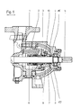
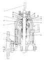
- the shaft sealing housing 2 as a unit housing and the ball bearing bracket 3 with the bearing housing 17 as a further housing are flanged to the pump housing 1.
- the shaft 5 is supported in the bearing housing 17 by means of the ball bearing 16.
- An axially acting mechanical seal 6 is provided to seal the shaft 5.
- a throttle bushing 8, which is located between the inner circumferential surface of the throttle bushing 7 and the outer circumferential surface of the shaft 5, is connected upstream on its low-pressure side as an additional flow obstacle.
- an intermediate space 9 is arranged, which has a control connection 10 for applying a pressure, not shown here, to the pressure prevailing in the intermediate space 9.
- the leakage can also be discharged in a targeted and controlled manner via the control connection 10.
- a lip seal 15 is provided in the bearing housing 17, which only serves to protect the bearing in normal operation, but blocks the passage of the leakage medium through the bearing housing in the event of a leak.
- bracket 3 is open.
- a groove 11 is arranged on the end face of the shaft sealing housing cover 4, the groove base of which is connected to the intermediate space 9 via the channel 12.
- An O-ring is arranged in the groove 11 as a secondary seal 13, which lies in the non-sealing ready position in the depth of the groove and does not have to touch the inner end wall 14 of the bearing housing 17.
- the pumped medium penetrates into the intermediate space 9 and causes the pressure to rise there. Via the channel 12, the side of the O-ring 13 facing the bottom of the groove is then subjected to this pressure, so that the O-ring 13 is displaced axially in the direction of the inner end wall 14 of the bearing housing 17 until it lies sealingly against this inner end wall 14 .
- This position of the O-ring 13 is shown in the drawing.
- Medium passing through the throttle section 8 of the throttle bushing 7 can then no longer escape radially outwards.
- the lip seal 15 prevents axial escape in the direction of the ball bearing 16.
- the seal 15 can be formed by any type of such seals which are only pressed more firmly against the counter-sealing surface by the pressure to be sealed.
- the term lip seal is to be interpreted broadly in this sense and includes in particular seals such as are provided for the encapsulation of ball bearings.
- a sensor connected to the control connection 10 can register a pressure increase in the intermediate space 9 caused by the failure of the sliding seal 6 and can then cause the pump to be switched off.
- the sealing ring 13 can be of simple design, since it is only subjected to static loads.
- the secondary seal is also conceivable. It can be provided that the O-ring 13 is pressed radially against the shaft. Because in the event of a failure the sealing, the corresponding unit is shut down immediately, the sealing ring pressed radially against the shaft only has to seal dynamically for a relatively short time, then it only has to statically seal against the standing shaft until the unit is ready for repair. For this reason, in this embodiment, the wear resistance of the sealing ring does not have to meet high requirements.
Landscapes
- Engineering & Computer Science (AREA)
- General Engineering & Computer Science (AREA)
- Mechanical Engineering (AREA)
- Sealing Devices (AREA)
- Structures Of Non-Positive Displacement Pumps (AREA)
Applications Claiming Priority (4)
| Application Number | Priority Date | Filing Date | Title |
|---|---|---|---|
| DE4118845 | 1991-06-07 | ||
| DE4118845 | 1991-06-07 | ||
| DE19924217609 DE4217609A1 (de) | 1991-06-07 | 1992-05-27 | Wellendurchfuehrung |
| DE4217609 | 1992-05-27 |
Publications (2)
| Publication Number | Publication Date |
|---|---|
| EP0517280A2 true EP0517280A2 (fr) | 1992-12-09 |
| EP0517280A3 EP0517280A3 (en) | 1993-10-06 |
Family
ID=25904356
Family Applications (1)
| Application Number | Title | Priority Date | Filing Date |
|---|---|---|---|
| EP19920109685 Withdrawn EP0517280A3 (en) | 1991-06-07 | 1992-06-09 | Shaft passage |
Country Status (2)
| Country | Link |
|---|---|
| EP (1) | EP0517280A3 (fr) |
| DE (1) | DE4217609A1 (fr) |
Cited By (1)
| Publication number | Priority date | Publication date | Assignee | Title |
|---|---|---|---|---|
| EP0637713A1 (fr) * | 1993-08-05 | 1995-02-08 | Honeywell Ag | Système de diagnostic pour des soupapes de réglage et d'arrêt |
Families Citing this family (1)
| Publication number | Priority date | Publication date | Assignee | Title |
|---|---|---|---|---|
| DE10013154A1 (de) | 2000-03-17 | 2001-09-20 | Ksb Ag | Wellenabdichtung |
Family Cites Families (5)
| Publication number | Priority date | Publication date | Assignee | Title |
|---|---|---|---|---|
| GB927609A (en) * | 1959-02-18 | 1963-05-29 | Volvo Ab | Improvements in sealing devices for hydraulic systems |
| US4085941A (en) * | 1976-06-11 | 1978-04-25 | Crane Packing Limited | Stern seals for ships |
| US4094512A (en) * | 1976-07-14 | 1978-06-13 | Crane Packing Limited | Shaft seals |
| US4114058A (en) * | 1976-09-03 | 1978-09-12 | Westinghouse Electric Corp. | Seal arrangement for a discharge chamber for water cooled turbine generator rotor |
| DE3203134C2 (de) * | 1982-01-30 | 1984-01-05 | Tbt Tiefbohrtechnik Gmbh Und Co Kg, 7433 Dettingen | Tiefbohrwerkzeug |
-
1992
- 1992-05-27 DE DE19924217609 patent/DE4217609A1/de not_active Withdrawn
- 1992-06-09 EP EP19920109685 patent/EP0517280A3/de not_active Withdrawn
Cited By (1)
| Publication number | Priority date | Publication date | Assignee | Title |
|---|---|---|---|---|
| EP0637713A1 (fr) * | 1993-08-05 | 1995-02-08 | Honeywell Ag | Système de diagnostic pour des soupapes de réglage et d'arrêt |
Also Published As
| Publication number | Publication date |
|---|---|
| EP0517280A3 (en) | 1993-10-06 |
| DE4217609A1 (de) | 1992-12-10 |
Similar Documents
| Publication | Publication Date | Title |
|---|---|---|
| DE68921755T2 (de) | Dynamische dichtungsanordnung für eine schraubenpumpe. | |
| DE2153560C3 (de) | Sperrflüssigkeitsdichtung | |
| EP0789147A2 (fr) | Pompe haute-pression à plongeur, travaillant de préférence à des pressions supérieures à 2000 bars | |
| DE4005428A1 (de) | Sperrfluessigkeits-dichtungsanordnung bei einem turboverdichter | |
| DE2624535A1 (de) | Vorrichtung zum umruesten von stopfbuchsen | |
| EP0056222B1 (fr) | Vanne à papillon | |
| DE69618355T2 (de) | Wellendichtung | |
| DE1303585B (de) | Druckkammerdichtung für einen hydraulischen Drehstellmotor | |
| DE102014211690A1 (de) | Fluidenergiemaschine, Verfahren zum Betrieb | |
| EP0517280A2 (fr) | Passage d'arbre | |
| DE19631824A1 (de) | Kreiselpumpenlagerung mit Axialschubausgleich | |
| DE102020002672B4 (de) | Becherförmiges Stellventil-Abschlussteil | |
| DE3737344A1 (de) | Wellendichtung fuer gasgefuellte elektrische maschinen | |
| DE102022108547A1 (de) | Gerotorpumpe mit verbesserter Dichtung | |
| DE102011004901B4 (de) | Dichtungssystem | |
| DE10242735A1 (de) | Hydrodynamischer Retarder mit wenigstens drei Dichtelementen | |
| DE2557376A1 (de) | Selbstzentrierende buchsen-anordnung | |
| WO1996016286A1 (fr) | Systeme d'etancheite | |
| DE4328856C2 (de) | Sperrgasabdichtung an einer Welle einer Durchführung eines unter Überdruck stehenden Gehäuses, insbesondere einer Gichtgasentspannungsturbine | |
| DE19742882C1 (de) | Radialer Schwenkmotor | |
| DD230913A1 (de) | Sicherheitsflanschverbindung | |
| AT401042B (de) | Vorrichtung zum abdichten der rotorwellengehäusedurchführung einer druckdichten zellenradschleuse | |
| DE3008491A1 (de) | Gleitringdichtung | |
| DE202006019205U1 (de) | Dichtungsanordnung, insbesondere zum Abdichten klebriger flüssiger Produkte | |
| DE1700137A1 (de) | Axiale Beruehrungsdichtung zwischen einer umlaufenden und einer stillstehenden Dichtflaeche zur Abdichtung von Wellen gegen Fluessigkeitsdurchtritt |
Legal Events
| Date | Code | Title | Description |
|---|---|---|---|
| PUAI | Public reference made under article 153(3) epc to a published international application that has entered the european phase |
Free format text: ORIGINAL CODE: 0009012 |
|
| AK | Designated contracting states |
Kind code of ref document: A2 Designated state(s): AT BE CH DE DK ES FR GB GR IT LI LU MC NL PT SE |
|
| PUAL | Search report despatched |
Free format text: ORIGINAL CODE: 0009013 |
|
| AK | Designated contracting states |
Kind code of ref document: A3 Designated state(s): AT BE CH DE DK ES FR GB GR IT LI LU MC NL PT SE |
|
| 17P | Request for examination filed |
Effective date: 19930927 |
|
| 17Q | First examination report despatched |
Effective date: 19940901 |
|
| STAA | Information on the status of an ep patent application or granted ep patent |
Free format text: STATUS: THE APPLICATION IS DEEMED TO BE WITHDRAWN |
|
| 18D | Application deemed to be withdrawn |
Effective date: 19950314 |