EP0789147A2 - Pompe haute-pression à plongeur, travaillant de préférence à des pressions supérieures à 2000 bars - Google Patents
Pompe haute-pression à plongeur, travaillant de préférence à des pressions supérieures à 2000 bars Download PDFInfo
- Publication number
- EP0789147A2 EP0789147A2 EP97100707A EP97100707A EP0789147A2 EP 0789147 A2 EP0789147 A2 EP 0789147A2 EP 97100707 A EP97100707 A EP 97100707A EP 97100707 A EP97100707 A EP 97100707A EP 0789147 A2 EP0789147 A2 EP 0789147A2
- Authority
- EP
- European Patent Office
- Prior art keywords
- inner body
- valve
- pressure
- valve seat
- plunger pump
- Prior art date
- Legal status (The legal status is an assumption and is not a legal conclusion. Google has not performed a legal analysis and makes no representation as to the accuracy of the status listed.)
- Granted
Links
- 238000003780 insertion Methods 0.000 claims description 10
- 230000037431 insertion Effects 0.000 claims description 10
- 230000007704 transition Effects 0.000 claims description 5
- 239000007788 liquid Substances 0.000 claims description 2
- 238000007789 sealing Methods 0.000 description 2
- 230000001154 acute effect Effects 0.000 description 1
- 239000000919 ceramic Substances 0.000 description 1
- 230000000694 effects Effects 0.000 description 1
- 230000005489 elastic deformation Effects 0.000 description 1
- 210000003746 feather Anatomy 0.000 description 1
- 238000004519 manufacturing process Methods 0.000 description 1
- 239000002184 metal Substances 0.000 description 1
Images
Classifications
-
- F—MECHANICAL ENGINEERING; LIGHTING; HEATING; WEAPONS; BLASTING
- F04—POSITIVE - DISPLACEMENT MACHINES FOR LIQUIDS; PUMPS FOR LIQUIDS OR ELASTIC FLUIDS
- F04B—POSITIVE-DISPLACEMENT MACHINES FOR LIQUIDS; PUMPS
- F04B53/00—Component parts, details or accessories not provided for in, or of interest apart from, groups F04B1/00 - F04B23/00 or F04B39/00 - F04B47/00
- F04B53/10—Valves; Arrangement of valves
- F04B53/1087—Valve seats
-
- F—MECHANICAL ENGINEERING; LIGHTING; HEATING; WEAPONS; BLASTING
- F04—POSITIVE - DISPLACEMENT MACHINES FOR LIQUIDS; PUMPS FOR LIQUIDS OR ELASTIC FLUIDS
- F04B—POSITIVE-DISPLACEMENT MACHINES FOR LIQUIDS; PUMPS
- F04B53/00—Component parts, details or accessories not provided for in, or of interest apart from, groups F04B1/00 - F04B23/00 or F04B39/00 - F04B47/00
- F04B53/007—Cylinder heads
-
- F—MECHANICAL ENGINEERING; LIGHTING; HEATING; WEAPONS; BLASTING
- F04—POSITIVE - DISPLACEMENT MACHINES FOR LIQUIDS; PUMPS FOR LIQUIDS OR ELASTIC FLUIDS
- F04B—POSITIVE-DISPLACEMENT MACHINES FOR LIQUIDS; PUMPS
- F04B53/00—Component parts, details or accessories not provided for in, or of interest apart from, groups F04B1/00 - F04B23/00 or F04B39/00 - F04B47/00
- F04B53/10—Valves; Arrangement of valves
- F04B53/102—Disc valves
- F04B53/1032—Spring-actuated disc valves
-
- F—MECHANICAL ENGINEERING; LIGHTING; HEATING; WEAPONS; BLASTING
- F04—POSITIVE - DISPLACEMENT MACHINES FOR LIQUIDS; PUMPS FOR LIQUIDS OR ELASTIC FLUIDS
- F04B—POSITIVE-DISPLACEMENT MACHINES FOR LIQUIDS; PUMPS
- F04B53/00—Component parts, details or accessories not provided for in, or of interest apart from, groups F04B1/00 - F04B23/00 or F04B39/00 - F04B47/00
- F04B53/16—Casings; Cylinders; Cylinder liners or heads; Fluid connections
- F04B53/162—Adaptations of cylinders
Definitions
- the invention relates to a high-pressure plunger pump, preferably for working pressures above 2,000 bar, with a pump head, a housing, a drivable plunger, a pressure and suction valve arranged coaxially to the longitudinal axis of the plunger, and an inner body having the working space of the pump, which is provided by a suction chamber containing liquid to be sucked is enclosed.
- a high-pressure plunger pump of this type is known (EP 0 551 590), in which the inner body having the working space of the pump is designed as a floating sleeve on the plunger. At the end facing the suction valve, the interior of the sleeve tapers, so that during the pressure stroke the sleeve is pressed against an insert body by the conveying medium.
- This insert body is formed in two parts, the part facing the plunger having the seat of the suction valve and the part facing the pump head having the seat of the pressure valve.
- the invention has for its object a high pressure plunger pump, preferably for working pressures above 2,000 bar to design that it is composed of a few, easy-to-manufacture components that ensure a good seal between the work and the suction space.
- the plunger is slidably mounted in a longitudinal bore of the inner body and in an insertion sleeve received by an extension of the longitudinal bore, the insertion sleeve is provided with an annular flange at the end facing the plunger drive and in the transition area from the annular flange to the sleeve body a seal is arranged between the working space and the suction space.
- the expansion is eliminated by the elasticity under the operating pressure, since the working pressure from outside and inside prevails up to the seal near the ring flange. Since the sealing gap is included in the calculation of the leakage rate in the third power, the leakage rate is significantly reduced in the embodiment according to the invention.
- the piston made of hard metal or ceramic shows hardly any signs of wear. From time to time only the insert sleeve has to be replaced.
- a valve seat ring with valve seat surfaces for the pressure valve and for the suction valve is provided in the space between the pump head and the inner body containing the working space.
- a suction valve body equipped with a central overflow bore and an associated spring are arranged in a cylindrical recess of the inner body adjoining the valve seat ring.
- the pump head is connected to the inner body.
- this connection between the pump head and the inner body is carried out by screws which start from the outer boundary surface of the pump head and are screwed with their threaded shank into threaded bores in the inner body of the pump.
- valve seat ring which has both the seat surface for the suction valve and the seat surface for the pressure valve.
- the harmful space is kept particularly small in order to offer the compressibility of the medium as little chance as possible of worsening the efficiency.
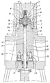
- the high-pressure plunger pump shown in the drawing has a housing 1 and a pump head 2 and is equipped with an inner body 3, which is enclosed by the suction chamber 4 of the pump and is connected to the pump head 2 by screws 5. These screws 5 extend from the outer surface 6 of the pump head over the entire height of the pump head and are screwed with their threaded shaft 7 into threaded bores 8 of the inner body 3.
- valve seat ring 9 is provided, which is positively connected to both the pump head 2 and the inner body 3.
- the valve seat ring 9 is provided with a sleeve-shaped insert 10, which forms the seat for the pressure valve 11.
- the seat surface is provided for an annular suction valve body 12 which has a central overflow bore 13a.
- a spring 14 is assigned to the suction valve body 12.
- Both the suction valve body 12 and the spring 14 are arranged in a stepped bore in the inner body 3.
- suction channels 15 extend to the seat 13 of the suction valve. These suction channels run at an acute angle to the central longitudinal axis 16 of the valve seat ring or the high-pressure plunger pump, in which the pressure valve and the suction valve are arranged coaxially.
- the pump is equipped with a drivable plunger 17, which is slidably mounted in a longitudinal bore 18 of the inner body 3 and in an insertion sleeve 19.
- the insertion sleeve 19 is provided with an annular flange 20 and is received by an extension 21 of the longitudinal bore 18.
- the ring flange 20 of the insertion sleeve 19 is arranged in a recess of the inner body 3 corresponding to the contour of the ring flange.
- a triple step of a recess is provided at the end facing the valve seat ring 9.
- One step is provided for the spring 14, another step for the suction valve body 12 and one step for a projection 26 of the valve seat ring 9.
- valve seat 9 A positive connection between the valve seat 9 and the pump head 2 is achieved by a stepped projection 27 of the valve seat ring 9, which engage in corresponding recesses in the pump head 2.
Landscapes
- Engineering & Computer Science (AREA)
- Mechanical Engineering (AREA)
- General Engineering & Computer Science (AREA)
- Details Of Reciprocating Pumps (AREA)
- Safety Valves (AREA)
Applications Claiming Priority (2)
| Application Number | Priority Date | Filing Date | Title |
|---|---|---|---|
| DE19604132A DE19604132C2 (de) | 1996-02-06 | 1996-02-06 | Hochdruckplungerpumpe, vorzugsweise für Arbeitsdrücke oberhalb 2.000 bar |
| DE19604132 | 1996-02-06 |
Publications (3)
| Publication Number | Publication Date |
|---|---|
| EP0789147A2 true EP0789147A2 (fr) | 1997-08-13 |
| EP0789147A3 EP0789147A3 (fr) | 1998-09-02 |
| EP0789147B1 EP0789147B1 (fr) | 2001-10-31 |
Family
ID=7784564
Family Applications (1)
| Application Number | Title | Priority Date | Filing Date |
|---|---|---|---|
| EP97100707A Expired - Lifetime EP0789147B1 (fr) | 1996-02-06 | 1997-01-17 | Pompe haute-pression à plongeur, travaillant de préférence à des pressions supérieures à 2000 bars |
Country Status (7)
| Country | Link |
|---|---|
| US (1) | US5848880A (fr) |
| EP (1) | EP0789147B1 (fr) |
| JP (1) | JP3954143B2 (fr) |
| AU (1) | AU705265B2 (fr) |
| DE (2) | DE19604132C2 (fr) |
| DK (1) | DK0789147T3 (fr) |
| ES (1) | ES2166476T3 (fr) |
Families Citing this family (33)
| Publication number | Priority date | Publication date | Assignee | Title |
|---|---|---|---|---|
| DE29716906U1 (de) * | 1997-07-17 | 1997-11-20 | Eberherr, Herbert, 97638 Mellrichstadt | Pumpenkopf für eine Hub-Kolbenpumpe |
| EP0892174B1 (fr) | 1997-07-17 | 2001-10-31 | Jürgen Weigel | Tête de pompe pour pompe à piston |
| US5980224A (en) * | 1997-12-18 | 1999-11-09 | Chrysler Corporation | Fuel injection pump |
| DE20008015U1 (de) | 2000-05-05 | 2000-08-31 | Neuman & Esser Maschinenfabrik GmbH & Co. KG, 52531 Übach-Palenberg | Geschrumpfter Zylinder für Hochdruck-Kolbenkompressoren |
| CN100453804C (zh) * | 2007-09-05 | 2009-01-21 | 吴赛珍 | 缸体大圆端面对内花键垂直的加工方法 |
| US8986253B2 (en) | 2008-01-25 | 2015-03-24 | Tandem Diabetes Care, Inc. | Two chamber pumps and related methods |
| DE202008001458U1 (de) * | 2008-02-01 | 2008-03-27 | Hammelmann Maschinenfabrik Gmbh | Hochdruckventilanordnung |
| US8408421B2 (en) | 2008-09-16 | 2013-04-02 | Tandem Diabetes Care, Inc. | Flow regulating stopcocks and related methods |
| CA2737461A1 (fr) | 2008-09-19 | 2010-03-25 | Tandem Diabetes Care, Inc. | Dispositif de mesure de la concentration d'un solute et procedes associes |
| US8926561B2 (en) | 2009-07-30 | 2015-01-06 | Tandem Diabetes Care, Inc. | Infusion pump system with disposable cartridge having pressure venting and pressure feedback |
| US9180242B2 (en) | 2012-05-17 | 2015-11-10 | Tandem Diabetes Care, Inc. | Methods and devices for multiple fluid transfer |
| US9095955B2 (en) | 2012-08-16 | 2015-08-04 | Omax Corporation | Control valves for waterjet systems and related devices, systems and methods |
| US8904912B2 (en) | 2012-08-16 | 2014-12-09 | Omax Corporation | Control valves for waterjet systems and related devices, systems, and methods |
| US9173998B2 (en) | 2013-03-14 | 2015-11-03 | Tandem Diabetes Care, Inc. | System and method for detecting occlusions in an infusion pump |
| CA2955874A1 (fr) * | 2014-03-31 | 2015-10-08 | Saudi Basic Industries Corporation | Procede pour la preparation d'un copolymere d'ethylene dans un reacteur tubulaire |
| US11554461B1 (en) | 2018-02-13 | 2023-01-17 | Omax Corporation | Articulating apparatus of a waterjet system and related technology |
| US11578710B2 (en) | 2019-05-02 | 2023-02-14 | Kerr Machine Co. | Fracturing pump with in-line fluid end |
| US12264661B2 (en) | 2019-11-18 | 2025-04-01 | Kerr Machine Co. | High pressure pump |
| US12188458B2 (en) | 2019-11-18 | 2025-01-07 | Kerr Machine Co. | Fluid end assembly |
| WO2021102001A1 (fr) | 2019-11-18 | 2021-05-27 | Kerr Machine Co. | Bouchon d'acheminement de fluide |
| US11635068B2 (en) | 2019-11-18 | 2023-04-25 | Kerr Machine Co. | Modular power end |
| US12292040B2 (en) | 2019-11-18 | 2025-05-06 | Kerr Machine Co. | High pressure pump |
| US11644018B2 (en) | 2019-11-18 | 2023-05-09 | Kerr Machine Co. | Fluid end |
| US11686296B2 (en) | 2019-11-18 | 2023-06-27 | Kerr Machine Co. | Fluid routing plug |
| US11578711B2 (en) | 2019-11-18 | 2023-02-14 | Kerr Machine Co. | Fluid routing plug |
| WO2021127253A1 (fr) | 2019-12-18 | 2021-06-24 | Hypertherm, Inc. | Systèmes et procédés de capteur de tête de coupe à jet de liquide |
| EP4127527A1 (fr) | 2020-03-24 | 2023-02-08 | Hypertherm, Inc. | Joint haute pression pour système de coupe à jet de liquide |
| KR20230005840A (ko) | 2020-03-30 | 2023-01-10 | 하이퍼썸, 인크. | 다기능 접속 종방향 단부들을 갖는 액체 제트 펌프를 위한 실린더 |
| US11920583B2 (en) | 2021-03-05 | 2024-03-05 | Kerr Machine Co. | Fluid end with clamped retention |
| DE102021112742A1 (de) | 2021-05-17 | 2022-11-17 | Hammelmann GmbH | Dichtungseinrichtung für eine Stange |
| US11946465B2 (en) | 2021-08-14 | 2024-04-02 | Kerr Machine Co. | Packing seal assembly |
| US11808364B2 (en) | 2021-11-11 | 2023-11-07 | Kerr Machine Co. | Valve body |
| US12297827B2 (en) | 2023-06-05 | 2025-05-13 | Kerr Machine Co. | Fluid end with clamped retention |
Citations (1)
| Publication number | Priority date | Publication date | Assignee | Title |
|---|---|---|---|---|
| EP0551590A1 (fr) | 1992-01-11 | 1993-07-21 | Paul Hammelmann | Pompe haute-pression à plongeur, travaillant de préférence à des pressions supérieures à 2000 bars |
Family Cites Families (17)
| Publication number | Priority date | Publication date | Assignee | Title |
|---|---|---|---|---|
| US2656820A (en) * | 1948-03-16 | 1953-10-27 | Philip S Becker | Power-operated vise |
| US3260217A (en) * | 1964-08-05 | 1966-07-12 | Frank Wheatley Pump & Valve Ma | Pump having radial discharge valve |
| US3298319A (en) * | 1964-10-26 | 1967-01-17 | Donald W Barlow | Pumping system for slurry and other solutions |
| US3811801A (en) * | 1972-05-30 | 1974-05-21 | Ingersoll Rand Co | Multi-plunger reciprocating pump |
| US3891356A (en) * | 1973-11-21 | 1975-06-24 | Armco Steel Corp | Fluid guide plunger system |
| DE3404520C2 (de) * | 1984-02-09 | 1997-01-09 | Uraca Pumpen | Pumpe oder Hydraulikanlage |
| DE8717850U1 (de) * | 1987-03-24 | 1990-08-09 | Hammelmann, Paul, 4740 Oelde | Hochdruckplungerpumpe |
| EP0393800B1 (fr) * | 1988-03-23 | 1994-08-17 | Kabushiki Kaisha Little Rock | Dispositif de clapet |
| US4878815A (en) * | 1988-05-18 | 1989-11-07 | Stachowiak J Edward | High pressure reciprocating pump apparatus |
| US5050895A (en) * | 1989-04-04 | 1991-09-24 | Flow International Corporation | High pressure dynamic seal |
| US5064354A (en) * | 1990-06-04 | 1991-11-12 | Robertson Walter W | High pressure fluid pump |
| DE4038613C3 (de) * | 1990-12-04 | 1998-09-17 | Woma Maasberg Co Gmbh W | Mehrzylindrige Hochdruckplungerpumpe |
| US5230363A (en) * | 1991-04-10 | 1993-07-27 | Dowell Schlumberger Incorporated | Suction valve for high pressure slurry pump |
| US5273405A (en) * | 1992-07-07 | 1993-12-28 | Jet Edge, Inc. | Fluid cushioning apparatus for hydraulic intensifier assembly |
| DE4240590A1 (de) * | 1992-12-03 | 1994-06-09 | Uraca Pumpen | Verdrängerpumpe |
| WO1994020754A1 (fr) * | 1993-03-12 | 1994-09-15 | Saurwein Albert C | Appareil multiplicateur de pression de fluide |
| US5493954A (en) * | 1994-11-18 | 1996-02-27 | Flow International Corporation | Self-venting seal assembly |
-
1996
- 1996-02-06 DE DE19604132A patent/DE19604132C2/de not_active Expired - Fee Related
-
1997
- 1997-01-17 DE DE59705122T patent/DE59705122D1/de not_active Expired - Lifetime
- 1997-01-17 EP EP97100707A patent/EP0789147B1/fr not_active Expired - Lifetime
- 1997-01-17 DK DK97100707T patent/DK0789147T3/da active
- 1997-01-17 ES ES97100707T patent/ES2166476T3/es not_active Expired - Lifetime
- 1997-01-29 US US08/790,390 patent/US5848880A/en not_active Expired - Lifetime
- 1997-01-30 AU AU12400/97A patent/AU705265B2/en not_active Ceased
- 1997-02-05 JP JP02262797A patent/JP3954143B2/ja not_active Expired - Fee Related
Patent Citations (1)
| Publication number | Priority date | Publication date | Assignee | Title |
|---|---|---|---|---|
| EP0551590A1 (fr) | 1992-01-11 | 1993-07-21 | Paul Hammelmann | Pompe haute-pression à plongeur, travaillant de préférence à des pressions supérieures à 2000 bars |
Also Published As
| Publication number | Publication date |
|---|---|
| EP0789147B1 (fr) | 2001-10-31 |
| JP3954143B2 (ja) | 2007-08-08 |
| DE19604132C2 (de) | 2000-04-13 |
| DE59705122D1 (de) | 2001-12-06 |
| DK0789147T3 (da) | 2002-02-18 |
| ES2166476T3 (es) | 2002-04-16 |
| JPH09228965A (ja) | 1997-09-02 |
| DE19604132A1 (de) | 1997-08-07 |
| AU1240097A (en) | 1997-08-14 |
| US5848880A (en) | 1998-12-15 |
| AU705265B2 (en) | 1999-05-20 |
| EP0789147A3 (fr) | 1998-09-02 |
Similar Documents
| Publication | Publication Date | Title |
|---|---|---|
| EP0789147B1 (fr) | Pompe haute-pression à plongeur, travaillant de préférence à des pressions supérieures à 2000 bars | |
| DE69512979T2 (de) | Flüssigkeitspumpe | |
| EP0256221A1 (fr) | Dispositif d'étanchéité pour tige | |
| DE4239362A1 (de) | Ventil, insbesondere Druckventil für eine Radialkolbenpumpe, mit wenigen Komponenten | |
| DE2323455A1 (de) | Dichtring fuer kolbenringe | |
| WO2000071913A1 (fr) | Dispositif d'etancheite pour un piston soumis a l'action d'un fluide sous pression dans un cylindre de travail | |
| DE2615530A1 (de) | Hochdruckplungerpumpe | |
| DE2834895C2 (de) | Hydraulische Formschließvorrichtung mit einem Druckübersetzer | |
| DE3232083A1 (de) | Radialkolbenpumpe | |
| DE102012224317A1 (de) | Steckpumpe | |
| EP0551590B1 (fr) | Pompe haute-pression à plongeur, travaillant de préférence à des pressions supérieures à 2000 bars | |
| EP0707166A1 (fr) | Joint d'étanchéité | |
| DE2317357C3 (fr) | ||
| DE2829351A1 (de) | Leckgas-rueckfuehrvorrichtung fuer eine stirling-maschine | |
| DE3420890C2 (fr) | ||
| EP0925453B1 (fr) | Pompe a cellules semi-rotatives | |
| DE719353C (de) | Wellenspaltdichtung fuer stopfbuechslose Kreiselpumpen | |
| EP1604112B1 (fr) | Pompe a pistons radiaux | |
| DE102007020298A1 (de) | Kolbenpumpe für ein Hochdruckreinigungsgerät | |
| WO2004025123A1 (fr) | Pompe pour appareil de nettoyage haute pression | |
| DE29623354U1 (de) | Hochdruckplungerpumpe, vorzugsweise für Arbeitsdrücke oberhalb 2.000 bar | |
| DE102019128682A1 (de) | Fördervorrichtung zumindest zu einem Fördern eines Fluids und Pumpe mit einer derartigen Fördervorrichtung | |
| DE202608C (fr) | ||
| DE2640440A1 (de) | Dosier-kolbenpumpe | |
| DE3337839C2 (de) | Pumpenaggregat |
Legal Events
| Date | Code | Title | Description |
|---|---|---|---|
| PUAI | Public reference made under article 153(3) epc to a published international application that has entered the european phase |
Free format text: ORIGINAL CODE: 0009012 |
|
| AK | Designated contracting states |
Kind code of ref document: A2 Designated state(s): CH DE DK ES FR GB IT LI NL SE |
|
| PUAL | Search report despatched |
Free format text: ORIGINAL CODE: 0009013 |
|
| AK | Designated contracting states |
Kind code of ref document: A3 Designated state(s): CH DE DK ES FR GB IT LI NL SE |
|
| 17P | Request for examination filed |
Effective date: 19980818 |
|
| 17Q | First examination report despatched |
Effective date: 20000719 |
|
| GRAG | Despatch of communication of intention to grant |
Free format text: ORIGINAL CODE: EPIDOS AGRA |
|
| GRAG | Despatch of communication of intention to grant |
Free format text: ORIGINAL CODE: EPIDOS AGRA |
|
| GRAH | Despatch of communication of intention to grant a patent |
Free format text: ORIGINAL CODE: EPIDOS IGRA |
|
| GRAH | Despatch of communication of intention to grant a patent |
Free format text: ORIGINAL CODE: EPIDOS IGRA |
|
| RAP3 | Party data changed (applicant data changed or rights of an application transferred) |
Owner name: HAMMELMANN MASCHINENFABRIK GMBH |
|
| GRAA | (expected) grant |
Free format text: ORIGINAL CODE: 0009210 |
|
| AK | Designated contracting states |
Kind code of ref document: B1 Designated state(s): CH DE DK ES FR GB IT LI NL SE |
|
| REG | Reference to a national code |
Ref country code: CH Ref legal event code: EP |
|
| REG | Reference to a national code |
Ref country code: CH Ref legal event code: NV Representative=s name: ISLER & PEDRAZZINI AG |
|
| GBT | Gb: translation of ep patent filed (gb section 77(6)(a)/1977) |
Effective date: 20011031 |
|
| REF | Corresponds to: |
Ref document number: 59705122 Country of ref document: DE Date of ref document: 20011206 |
|
| REG | Reference to a national code |
Ref country code: GB Ref legal event code: IF02 |
|
| REG | Reference to a national code |
Ref country code: DK Ref legal event code: T3 |
|
| ET | Fr: translation filed | ||
| REG | Reference to a national code |
Ref country code: ES Ref legal event code: FG2A Ref document number: 2166476 Country of ref document: ES Kind code of ref document: T3 |
|
| PLBE | No opposition filed within time limit |
Free format text: ORIGINAL CODE: 0009261 |
|
| STAA | Information on the status of an ep patent application or granted ep patent |
Free format text: STATUS: NO OPPOSITION FILED WITHIN TIME LIMIT |
|
| 26N | No opposition filed | ||
| REG | Reference to a national code |
Ref country code: CH Ref legal event code: PCAR Free format text: ISLER & PEDRAZZINI AG;POSTFACH 1772;8027 ZUERICH (CH) |
|
| PGFP | Annual fee paid to national office [announced via postgrant information from national office to epo] |
Ref country code: DK Payment date: 20110125 Year of fee payment: 15 |
|
| PGFP | Annual fee paid to national office [announced via postgrant information from national office to epo] |
Ref country code: NL Payment date: 20110119 Year of fee payment: 15 Ref country code: IT Payment date: 20110126 Year of fee payment: 15 Ref country code: FR Payment date: 20110201 Year of fee payment: 15 Ref country code: SE Payment date: 20110121 Year of fee payment: 15 Ref country code: DE Payment date: 20110113 Year of fee payment: 15 Ref country code: CH Payment date: 20110125 Year of fee payment: 15 |
|
| PGFP | Annual fee paid to national office [announced via postgrant information from national office to epo] |
Ref country code: ES Payment date: 20110121 Year of fee payment: 15 Ref country code: GB Payment date: 20110121 Year of fee payment: 15 |
|
| REG | Reference to a national code |
Ref country code: NL Ref legal event code: V1 Effective date: 20120801 |
|
| REG | Reference to a national code |
Ref country code: CH Ref legal event code: PL |
|
| REG | Reference to a national code |
Ref country code: SE Ref legal event code: EUG |
|
| REG | Reference to a national code |
Ref country code: DK Ref legal event code: EBP |
|
| GBPC | Gb: european patent ceased through non-payment of renewal fee |
Effective date: 20120117 |
|
| REG | Reference to a national code |
Ref country code: FR Ref legal event code: ST Effective date: 20120928 |
|
| PG25 | Lapsed in a contracting state [announced via postgrant information from national office to epo] |
Ref country code: CH Free format text: LAPSE BECAUSE OF NON-PAYMENT OF DUE FEES Effective date: 20120131 Ref country code: LI Free format text: LAPSE BECAUSE OF NON-PAYMENT OF DUE FEES Effective date: 20120131 Ref country code: SE Free format text: LAPSE BECAUSE OF NON-PAYMENT OF DUE FEES Effective date: 20120118 Ref country code: GB Free format text: LAPSE BECAUSE OF NON-PAYMENT OF DUE FEES Effective date: 20120117 Ref country code: DE Free format text: LAPSE BECAUSE OF NON-PAYMENT OF DUE FEES Effective date: 20120801 |
|
| REG | Reference to a national code |
Ref country code: DE Ref legal event code: R119 Ref document number: 59705122 Country of ref document: DE Effective date: 20120801 |
|
| PG25 | Lapsed in a contracting state [announced via postgrant information from national office to epo] |
Ref country code: IT Free format text: LAPSE BECAUSE OF NON-PAYMENT OF DUE FEES Effective date: 20120117 |
|
| PG25 | Lapsed in a contracting state [announced via postgrant information from national office to epo] |
Ref country code: FR Free format text: LAPSE BECAUSE OF NON-PAYMENT OF DUE FEES Effective date: 20120131 |
|
| PG25 | Lapsed in a contracting state [announced via postgrant information from national office to epo] |
Ref country code: DK Free format text: LAPSE BECAUSE OF NON-PAYMENT OF DUE FEES Effective date: 20120131 Ref country code: NL Free format text: LAPSE BECAUSE OF NON-PAYMENT OF DUE FEES Effective date: 20120801 |
|
| REG | Reference to a national code |
Ref country code: ES Ref legal event code: FD2A Effective date: 20130705 |
|
| PG25 | Lapsed in a contracting state [announced via postgrant information from national office to epo] |
Ref country code: ES Free format text: LAPSE BECAUSE OF NON-PAYMENT OF DUE FEES Effective date: 20120118 |