EP0517655A1 - Procédé et dispositif d'ourdissage de fils sur le tambour d'ourdissage d'un ourdissoir sectionnel - Google Patents
Procédé et dispositif d'ourdissage de fils sur le tambour d'ourdissage d'un ourdissoir sectionnel Download PDFInfo
- Publication number
- EP0517655A1 EP0517655A1 EP92810387A EP92810387A EP0517655A1 EP 0517655 A1 EP0517655 A1 EP 0517655A1 EP 92810387 A EP92810387 A EP 92810387A EP 92810387 A EP92810387 A EP 92810387A EP 0517655 A1 EP0517655 A1 EP 0517655A1
- Authority
- EP
- European Patent Office
- Prior art keywords
- warping
- drum
- roller
- axis
- warping drum
- Prior art date
- Legal status (The legal status is an assumption and is not a legal conclusion. Google has not performed a legal analysis and makes no representation as to the accuracy of the status listed.)
- Granted
Links
Images
Classifications
-
- D—TEXTILES; PAPER
- D02—YARNS; MECHANICAL FINISHING OF YARNS OR ROPES; WARPING OR BEAMING
- D02H—WARPING, BEAMING OR LEASING
- D02H7/00—Combined warping and beaming machines
Definitions
- the invention relates to a method for warping threads onto the warping drum of a cone warping machine according to the preamble of claim 1.
- the invention also relates to a device according to the preamble of claim 5.
- the warping tape is wound directly onto the warping drum without being deflected.
- the warping must be adjusted to the drum, which requires a very complex control.
- the deflection of the warping belt downward via a deflection roller and the change in the direction of rotation of the warping drum bring about a surprisingly simple improvement in the winding quality.
- the geometric relationships between the individual components change in such a way that the point of contact of the warping belt on the warping drum or on the winding is practically immediately below the deflection roller. This shortens the entire length of the warp belt between the warp and the point of impact.
- Working on the warping machine, in particular when attaching crosshairs, is considerably simplified and the construction of the warping machine can also be simplified. However, elaborate warp blade controls for tracking the warp with respect to the angle of incidence of the warping belt are also not required.
- a simplification results in particular if the deflecting roller is designed directly as a measuring roller for measuring the strip tension and / or the strip length. Since the wrap angle on the deflecting roller is always approximately the same size in the thread guide according to the invention, a precise measurement of the belt tension can be carried out without additional means.
- a press roller which is arranged under the deflection roller and can be pressed against the warping belt drum, in order to equalize the application of the warping belt on the warping drum, directly presses the warping belt after the point of impact against the drum, without the warping belt first having to make an almost complete drum revolution. This also has a favorable influence on the winding quality.
- the press roller can nevertheless be used in a manner known per se for measuring the warping tape application.
- the treeing process after the warping i.e. the unwinding of the warp band together as a warp chain on the warp beam
- the warping of the warping chain was forced over the base point of the warping drum, the warping chain being guided relatively steeply upwards against a deflection roller between the warping drum and the warp beam or directly to the warp beam.
- the deflection angle on this deflection roller increased continuously.
- the deflection roller can also be used as a size roller, since the approximately constant wrap angle ensures a uniform application of size. However, even without an intermediate deflection, the processing of the warping chain via the apex is advantageous, since the warping chain is more visible and more accessible.
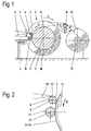
- the warping machine 1 consists, in a manner known per se, of a warping drum 2, which is held so that it can rotate in a frame (not shown here). It is a cone warping machine in which the individual warping tapes are wound up conically. The threads are drawn off from a creel (not shown) and arrive as a thread assembly 5 at a warping reel 7, where they are brought together to form a warping belt 3.
- the warping arm is fastened on a warping carriage 4 which, according to the cone inclination and the increasing winding thickness, is axially parallel and radially displaceable with respect to its distance from the warping drum.
- the movement of the warping carriage is carried out by control means, not shown here, which are also known per se to the person skilled in the art.
- a deflection roller 6 Arranged between the warping arm 7 and the warping drum 2 is a deflection roller 6, the axis 8 of which lies on a horizontal plane between the axis 9 of the warping drum 2 and the apex 10.
- the deflection roller 6 is assigned to the warping carriage 4 and thus moves together with the warping reel 7 relative to the warping drum 2.
- the deflection roller 6 is preferably a measuring roller, e.g. in accordance with CH-A-675 589, which can be deflected by the tension of the warping belt 3, the braking means on the creel being loosened with increasing deflection.
- a measuring roller e.g. in accordance with CH-A-675 589
- CH-A-675 589 a measuring roller
- a press roller 11 is arranged below the deflection roller 6 and can be pressed against the warping drum 2.
- the press roller is also assigned to the warping carriage 4 and moves together with the warping reel 7 and with the deflecting roller 6.
- the axis 12 of the press roller 11 is preferably arranged on the same horizontal plane as the axis 9 of the warping drum 2.
- the press roller 11 serves to equalize the tape application on the drum. At the same time, the tape application can be measured and the length dimension of the warping tape that has already been wound up can be calculated and kept the same for all warping tapes.
- the warping drum 2 is rotated in the direction of arrow a, so that the direction of rotation extends over the vertex 10 against the deflection roller 6.
- the run-up point 14 of the warping belt lies on the warping drum 2 or on the winding 18 below the deflection roller 6 and very close to the horizontal center plane of the warping drum.
- the free distance of the warping belt between leaving the deflection roller 6 and the run-up point can be kept extremely short during the entire work process.
- a partial cord 19 has to be inserted into the thread assembly 5 to form a crosshair, its handling is much easier than with conventional warping machines.
- the partial cord is introduced into the warping belt and onto the winding only via a single deflecting roller and in the shortest possible way.
- the partial cord is also attached to the warping drum in the lower half and not in the upper half of the warping drum, accessibility being made considerably easier.
- the warp beam 15 for treeing the finished warping chain 17 is mounted axially parallel directly next to the warping drum.
- the warping chain is fed to the warp beam via a deflection roller 16.
- This deflection roller is arranged such that its axis lies on a plane slightly above the apex 10 of the warping drum.
- the warping drum 2 is rotated in the direction of arrow b, the warping chain 17 being unwound over the vertex 10.
- the deflection angle of the warping chain 17 on the deflection roller 16 immediately at the beginning of the rearing ⁇ 1 changes only slightly until the end of the rearing process ⁇ 2.
- the deflecting roller 16 is therefore particularly advantageous as a measuring roller for measuring or regulating the warp tension.
- the deflecting roller 16 can also be designed as a corrugated roller, that is to say as a polygonal roller, which loosens warp threads connected by the continuous up and down movement of the warping chain.
- the deflecting roller 16 can also be used as a size roller for applying size.
- a major advantage is also the fact that the warping chain 17 of the Warping drum 2 to warp beam 15 can be monitored visually. This would not be practically possible if the direction of rotation is reversed or if the warping chain is unwound from the base of the warping drum.
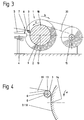
- FIGS. 3 and 4 show an alternative exemplary embodiment without a press roller below the deflecting roller 6. While in the exemplary embodiment according to FIGS. 1 and 2 the press roller 11 also takes on the function of a measuring roller for length measurement, the deflecting roller in the present exemplary embodiment can fulfill a double function in that it measures both the tension in the warping belt 3 and its length.
- the deflection roller 6 itself performs the function of a press roller and that for this purpose it is pressed against the warping drum or against the winding on the plane of the axis 9 of the warping drum. In this case, however, the deflection roller 6 could no longer measure the tension of the warping belt, since it would have to be pressed against the warping belt or against the winding against the resulting force of the deflected warping belt.
- the deflection roller 16 for the warping chain is also omitted in the case of trees.
- the warping chain 20 runs directly tangentially from the warping drum 2 to the warp beam 15. With this solution, too, the warping chain can be monitored much better than if the unwinding were carried out via the base point of the warping drum.
- the geometric arrangement of the individual rollers and their diameter can change depending on the application, without thereby leaving the subject matter of the invention.
- the axis 8 of the deflection roller 6 would lie practically on the same horizontal plane as the axis 9 of the warping drum 2. In this way, a bound belt guide could practically be achieved without the warping belt 3 having to travel a free and unbound distance.
Landscapes
- Engineering & Computer Science (AREA)
- Textile Engineering (AREA)
- Warping, Beaming, Or Leasing (AREA)
- Treatment Of Fiber Materials (AREA)
Applications Claiming Priority (2)
| Application Number | Priority Date | Filing Date | Title |
|---|---|---|---|
| CH1709/91A CH683433A5 (de) | 1991-06-07 | 1991-06-07 | Verfahren und Vorrichtung zum Schären von Fäden auf die Schärtrommel einer Schärmaschine. |
| CH1709/91 | 1991-06-07 |
Publications (2)
| Publication Number | Publication Date |
|---|---|
| EP0517655A1 true EP0517655A1 (fr) | 1992-12-09 |
| EP0517655B1 EP0517655B1 (fr) | 1996-07-31 |
Family
ID=4216775
Family Applications (1)
| Application Number | Title | Priority Date | Filing Date |
|---|---|---|---|
| EP19920810387 Expired - Lifetime EP0517655B1 (fr) | 1991-06-07 | 1992-05-22 | Procédé et dispositif d'ourdissage de fils sur le tambour d'ourdissage d'un ourdissoir sectionnel |
Country Status (4)
| Country | Link |
|---|---|
| EP (1) | EP0517655B1 (fr) |
| CH (1) | CH683433A5 (fr) |
| DE (1) | DE59206838D1 (fr) |
| ES (1) | ES2090570T3 (fr) |
Cited By (4)
| Publication number | Priority date | Publication date | Assignee | Title |
|---|---|---|---|---|
| EP0965668A3 (fr) * | 1998-06-17 | 2000-01-05 | Benninger AG | Procédé et dispositif pour transférer une nappe enroulée de fils sur une ensouple |
| EP1736578A3 (fr) * | 2005-06-22 | 2007-04-18 | H.k.o. Isolier- und Textiltechnik GmbH | Ourdissoir et procédé de fabrication d'un ensouple |
| CN105177790A (zh) * | 2015-08-17 | 2015-12-23 | 吴江市华运纺织品有限公司 | 一种大提花分批整经机 |
| CN109440248A (zh) * | 2018-09-28 | 2019-03-08 | 安徽省兰飞化纤织造有限公司 | 一种带有自动控制张力的整经涤纶单丝排线导向装置 |
Families Citing this family (2)
| Publication number | Priority date | Publication date | Assignee | Title |
|---|---|---|---|---|
| ES2255791B1 (es) * | 2003-10-20 | 2007-07-16 | Comsa Comercial, S.A. | Urdidor seccional para urdido de hilos. |
| CN111926437B (zh) * | 2020-08-06 | 2022-03-11 | 福州市长乐区山城针纺有限公司 | 一种整经机的纱线固定装置以及固定方法 |
Citations (9)
| Publication number | Priority date | Publication date | Assignee | Title |
|---|---|---|---|---|
| US1478082A (en) * | 1922-01-13 | 1923-12-18 | Whitlock Cleveland | Warping process |
| DE1814991A1 (de) * | 1967-12-20 | 1969-10-16 | Maquinaria Textil De Norte De | Verbesserungen an den Maschinen fuer direktes Aufwickeln von flachen Webketten auf den Kettbaum |
| DE2510517B2 (de) * | 1975-03-11 | 1978-10-19 | Hacoba Textilmaschinen Gmbh & Co Kg, 5600 Wuppertal | Verfahren und Vorrichtung zum Schären von Fäden |
| DE3103555A1 (de) * | 1981-02-03 | 1982-10-14 | W. Schlafhorst & Co, 4050 Mönchengladbach | Kettvorbereitungsmaschine |
| DE3149984A1 (de) * | 1981-12-17 | 1983-06-30 | Gebrüder Sucker, 4050 Mönchengladbach | Baeummaschine |
| DE3702293A1 (de) * | 1986-02-27 | 1987-09-03 | Benninger Ag Maschf | Verfahren zum schaeren von faeden auf die schaertrommel einer schaermaschine und schaermaschine |
| US4890368A (en) * | 1988-09-29 | 1990-01-02 | Reed-Chatwood, Inc. | Warper with tension isolator and tension controller |
| DE3900487A1 (de) * | 1989-01-10 | 1990-07-19 | Hacoba Textilmaschinen | Baeummaschine zum wahlweisen assemblieren und zetteln von textilen fadenscharen |
| DE4014358A1 (de) * | 1989-05-11 | 1990-11-15 | Benninger Ag Maschf | Wickelmaschine |
-
1991
- 1991-06-07 CH CH1709/91A patent/CH683433A5/de not_active IP Right Cessation
-
1992
- 1992-05-22 DE DE59206838T patent/DE59206838D1/de not_active Expired - Fee Related
- 1992-05-22 EP EP19920810387 patent/EP0517655B1/fr not_active Expired - Lifetime
- 1992-05-22 ES ES92810387T patent/ES2090570T3/es not_active Expired - Lifetime
Patent Citations (9)
| Publication number | Priority date | Publication date | Assignee | Title |
|---|---|---|---|---|
| US1478082A (en) * | 1922-01-13 | 1923-12-18 | Whitlock Cleveland | Warping process |
| DE1814991A1 (de) * | 1967-12-20 | 1969-10-16 | Maquinaria Textil De Norte De | Verbesserungen an den Maschinen fuer direktes Aufwickeln von flachen Webketten auf den Kettbaum |
| DE2510517B2 (de) * | 1975-03-11 | 1978-10-19 | Hacoba Textilmaschinen Gmbh & Co Kg, 5600 Wuppertal | Verfahren und Vorrichtung zum Schären von Fäden |
| DE3103555A1 (de) * | 1981-02-03 | 1982-10-14 | W. Schlafhorst & Co, 4050 Mönchengladbach | Kettvorbereitungsmaschine |
| DE3149984A1 (de) * | 1981-12-17 | 1983-06-30 | Gebrüder Sucker, 4050 Mönchengladbach | Baeummaschine |
| DE3702293A1 (de) * | 1986-02-27 | 1987-09-03 | Benninger Ag Maschf | Verfahren zum schaeren von faeden auf die schaertrommel einer schaermaschine und schaermaschine |
| US4890368A (en) * | 1988-09-29 | 1990-01-02 | Reed-Chatwood, Inc. | Warper with tension isolator and tension controller |
| DE3900487A1 (de) * | 1989-01-10 | 1990-07-19 | Hacoba Textilmaschinen | Baeummaschine zum wahlweisen assemblieren und zetteln von textilen fadenscharen |
| DE4014358A1 (de) * | 1989-05-11 | 1990-11-15 | Benninger Ag Maschf | Wickelmaschine |
Cited By (6)
| Publication number | Priority date | Publication date | Assignee | Title |
|---|---|---|---|---|
| EP0965668A3 (fr) * | 1998-06-17 | 2000-01-05 | Benninger AG | Procédé et dispositif pour transférer une nappe enroulée de fils sur une ensouple |
| US6192560B1 (en) | 1998-06-17 | 2001-02-27 | Benninger Ag | Method and device for transferring a yarn sheet from a yarn winder onto a winding beam |
| EP1736578A3 (fr) * | 2005-06-22 | 2007-04-18 | H.k.o. Isolier- und Textiltechnik GmbH | Ourdissoir et procédé de fabrication d'un ensouple |
| CN105177790A (zh) * | 2015-08-17 | 2015-12-23 | 吴江市华运纺织品有限公司 | 一种大提花分批整经机 |
| CN109440248A (zh) * | 2018-09-28 | 2019-03-08 | 安徽省兰飞化纤织造有限公司 | 一种带有自动控制张力的整经涤纶单丝排线导向装置 |
| CN109440248B (zh) * | 2018-09-28 | 2021-07-23 | 安徽省兰飞化纤织造有限公司 | 一种带有自动控制张力的整经涤纶单丝排线导向装置 |
Also Published As
| Publication number | Publication date |
|---|---|
| EP0517655B1 (fr) | 1996-07-31 |
| ES2090570T3 (es) | 1996-10-16 |
| CH683433A5 (de) | 1994-03-15 |
| DE59206838D1 (de) | 1996-09-05 |
Similar Documents
| Publication | Publication Date | Title |
|---|---|---|
| DE3202428A1 (de) | "verfahren und vorrichtung zum anspinnen eines fadens in einer offenend-spinnvorrichtung" | |
| DE60016329T2 (de) | Spann- und Rückziehvorrichtung für vom Spulengatter zur Webmaschine laufenden Kettfaden | |
| DE2522681C2 (de) | Vorrichtung zur Montage von spiralförmig gebogenen Rohren zur Herstellung von rotationssymmetrischen Bauteilen | |
| EP0289009A1 (fr) | Procédé et dispositif pour la surveillance et le maintien d'une qualité de fil prédéterminée | |
| DE4446279C1 (de) | Vorrichtung und Verfahren zum Herstellen von Kurzketten | |
| EP0517655B1 (fr) | Procédé et dispositif d'ourdissage de fils sur le tambour d'ourdissage d'un ourdissoir sectionnel | |
| DE2406550A1 (de) | Verfahren zum aufbringen von reservewindungen auf eine spulenhuelse zum aufwickeln von endlosfaeden und aufwickelvorrichtung zur durchfuehrung des verfahrens | |
| EP0593951A2 (fr) | Dispositif de filature | |
| DE2814382B2 (de) | Verfahren und Vorrichtung zum Ablegen einer Lunte in einen Behälter | |
| DE2247474A1 (de) | Verfahren und vorrichtung zum kompensieren der garnspannungsdiffenrenz zwischen zwei garnen auf einer antreibbaren spindel-aufspulvorrichtung | |
| DE2635200C2 (de) | Fadenzuführeinrichtung | |
| DE4436651C2 (de) | Einrichtung zum Bewickeln von langgestrecktem Gut | |
| DE2330961B2 (de) | Vorrichtung zur Bildung einer Fadenreserve auf einer Aufwickelspule mit wilder Wicklung an schnellaufenden Spulmaschinen | |
| DE2917666C2 (de) | Schärmaschine | |
| EP0904436B1 (fr) | Dispositif d'enroulement pour fils de cantres | |
| DE3205218C2 (de) | Fadenschärvorrichtung und Fadenschärverfahren | |
| DE2239341A1 (de) | Vorrichtung zum herstellen eines kuchens aus gewickelten straengen aus fasern oder faeden | |
| DE1660210A1 (de) | Vorrichtung zur Fadentrennung fuer Falschdraht-Kraeuselmaschinen | |
| DE2735898B2 (de) | Vorrichtung zur Herstellung einer gleichförmigen Fasergutablage beim | |
| DE2042550C3 (de) | Vorrichtung zum Schrägaufschneiden schlauchförmiger Textilware | |
| DE1535586B1 (de) | Vorrichtung zum Speichern und zum Einlegen der Schussfaeden bei Rundwebmaschinen | |
| DE2519231C2 (de) | Vorrichtung zur Überwachung von Kettfäden bei Schärmaschinen auf Flusen und Kapillarbrüche | |
| DE2349563C2 (de) | Vorrichtung zum Wickeln von fadenartigem Gut | |
| DE19526845A1 (de) | Friktionsspinnvorrichtung | |
| DE2543956C3 (fr) |
Legal Events
| Date | Code | Title | Description |
|---|---|---|---|
| PUAI | Public reference made under article 153(3) epc to a published international application that has entered the european phase |
Free format text: ORIGINAL CODE: 0009012 |
|
| AK | Designated contracting states |
Kind code of ref document: A1 Designated state(s): BE CH DE ES FR IT LI |
|
| 17P | Request for examination filed |
Effective date: 19930415 |
|
| 17Q | First examination report despatched |
Effective date: 19941123 |
|
| GRAH | Despatch of communication of intention to grant a patent |
Free format text: ORIGINAL CODE: EPIDOS IGRA |
|
| GRAA | (expected) grant |
Free format text: ORIGINAL CODE: 0009210 |
|
| AK | Designated contracting states |
Kind code of ref document: B1 Designated state(s): BE CH DE ES FR IT LI |
|
| REF | Corresponds to: |
Ref document number: 59206838 Country of ref document: DE Date of ref document: 19960905 |
|
| ET | Fr: translation filed | ||
| REG | Reference to a national code |
Ref country code: ES Ref legal event code: FG2A Ref document number: 2090570 Country of ref document: ES Kind code of ref document: T3 |
|
| ITF | It: translation for a ep patent filed | ||
| PLBQ | Unpublished change to opponent data |
Free format text: ORIGINAL CODE: EPIDOS OPPO |
|
| PLBI | Opposition filed |
Free format text: ORIGINAL CODE: 0009260 |
|
| REG | Reference to a national code |
Ref country code: ES Ref legal event code: FG2A Ref document number: 2090570 Country of ref document: ES Kind code of ref document: T3 |
|
| 26 | Opposition filed |
Opponent name: SUCKER-MUELLER-HACOBA GMBH & CO. Effective date: 19961029 |
|
| PLBF | Reply of patent proprietor to notice(s) of opposition |
Free format text: ORIGINAL CODE: EPIDOS OBSO |
|
| PLBF | Reply of patent proprietor to notice(s) of opposition |
Free format text: ORIGINAL CODE: EPIDOS OBSO |
|
| PLBO | Opposition rejected |
Free format text: ORIGINAL CODE: EPIDOS REJO |
|
| PLBN | Opposition rejected |
Free format text: ORIGINAL CODE: 0009273 |
|
| 27O | Opposition rejected |
Effective date: 19990127 |
|
| PGFP | Annual fee paid to national office [announced via postgrant information from national office to epo] |
Ref country code: CH Payment date: 20040811 Year of fee payment: 13 |
|
| PG25 | Lapsed in a contracting state [announced via postgrant information from national office to epo] |
Ref country code: LI Free format text: LAPSE BECAUSE OF NON-PAYMENT OF DUE FEES Effective date: 20050531 Ref country code: CH Free format text: LAPSE BECAUSE OF NON-PAYMENT OF DUE FEES Effective date: 20050531 |
|
| REG | Reference to a national code |
Ref country code: CH Ref legal event code: PL |
|
| PGFP | Annual fee paid to national office [announced via postgrant information from national office to epo] |
Ref country code: ES Payment date: 20090521 Year of fee payment: 18 |
|
| PGFP | Annual fee paid to national office [announced via postgrant information from national office to epo] |
Ref country code: IT Payment date: 20090529 Year of fee payment: 18 Ref country code: FR Payment date: 20090513 Year of fee payment: 18 Ref country code: DE Payment date: 20090525 Year of fee payment: 18 |
|
| PGFP | Annual fee paid to national office [announced via postgrant information from national office to epo] |
Ref country code: BE Payment date: 20090622 Year of fee payment: 18 |
|
| BERE | Be: lapsed |
Owner name: *BENNINGER A.G. Effective date: 20100531 |
|
| REG | Reference to a national code |
Ref country code: FR Ref legal event code: ST Effective date: 20110131 |
|
| PG25 | Lapsed in a contracting state [announced via postgrant information from national office to epo] |
Ref country code: IT Free format text: LAPSE BECAUSE OF NON-PAYMENT OF DUE FEES Effective date: 20100522 Ref country code: BE Free format text: LAPSE BECAUSE OF NON-PAYMENT OF DUE FEES Effective date: 20100531 |
|
| PG25 | Lapsed in a contracting state [announced via postgrant information from national office to epo] |
Ref country code: DE Free format text: LAPSE BECAUSE OF NON-PAYMENT OF DUE FEES Effective date: 20101201 |
|
| PG25 | Lapsed in a contracting state [announced via postgrant information from national office to epo] |
Ref country code: FR Free format text: LAPSE BECAUSE OF NON-PAYMENT OF DUE FEES Effective date: 20100531 |
|
| REG | Reference to a national code |
Ref country code: ES Ref legal event code: FD2A Effective date: 20110708 |
|
| PG25 | Lapsed in a contracting state [announced via postgrant information from national office to epo] |
Ref country code: ES Free format text: LAPSE BECAUSE OF NON-PAYMENT OF DUE FEES Effective date: 20110628 |
|
| PG25 | Lapsed in a contracting state [announced via postgrant information from national office to epo] |
Ref country code: ES Free format text: LAPSE BECAUSE OF NON-PAYMENT OF DUE FEES Effective date: 20100523 |