EP0518043B1 - Dispositif pour la coupe de bandes profilées en caoutchouc - Google Patents
Dispositif pour la coupe de bandes profilées en caoutchouc Download PDFInfo
- Publication number
- EP0518043B1 EP0518043B1 EP92107358A EP92107358A EP0518043B1 EP 0518043 B1 EP0518043 B1 EP 0518043B1 EP 92107358 A EP92107358 A EP 92107358A EP 92107358 A EP92107358 A EP 92107358A EP 0518043 B1 EP0518043 B1 EP 0518043B1
- Authority
- EP
- European Patent Office
- Prior art keywords
- shaft
- cutting
- cutter
- transverse movement
- cutting device
- Prior art date
- Legal status (The legal status is an assumption and is not a legal conclusion. Google has not performed a legal analysis and makes no representation as to the accuracy of the status listed.)
- Expired - Lifetime
Links
- 238000005520 cutting process Methods 0.000 title claims description 51
- 230000033001 locomotion Effects 0.000 claims description 26
- 230000005540 biological transmission Effects 0.000 claims description 4
- 238000003490 calendering Methods 0.000 claims description 2
- 238000001125 extrusion Methods 0.000 claims description 2
- 239000000203 mixture Substances 0.000 claims 1
- 238000005096 rolling process Methods 0.000 description 8
- 238000004519 manufacturing process Methods 0.000 description 6
- 230000001133 acceleration Effects 0.000 description 4
- 238000000034 method Methods 0.000 description 4
- 230000001012 protector Effects 0.000 description 2
- 230000035939 shock Effects 0.000 description 2
- 238000001816 cooling Methods 0.000 description 1
- 230000008878 coupling Effects 0.000 description 1
- 238000010168 coupling process Methods 0.000 description 1
- 238000005859 coupling reaction Methods 0.000 description 1
- 230000005484 gravity Effects 0.000 description 1
- 239000007788 liquid Substances 0.000 description 1
- 230000007246 mechanism Effects 0.000 description 1
- 239000003595 mist Substances 0.000 description 1
- 230000001681 protective effect Effects 0.000 description 1
Images


Classifications
-
- B—PERFORMING OPERATIONS; TRANSPORTING
- B26—HAND CUTTING TOOLS; CUTTING; SEVERING
- B26D—CUTTING; DETAILS COMMON TO MACHINES FOR PERFORATING, PUNCHING, CUTTING-OUT, STAMPING-OUT OR SEVERING
- B26D3/00—Cutting work characterised by the nature of the cut made; Apparatus therefor
- B26D3/003—Cutting work characterised by the nature of the cut made; Apparatus therefor specially adapted for cutting rubber
-
- B—PERFORMING OPERATIONS; TRANSPORTING
- B26—HAND CUTTING TOOLS; CUTTING; SEVERING
- B26D—CUTTING; DETAILS COMMON TO MACHINES FOR PERFORATING, PUNCHING, CUTTING-OUT, STAMPING-OUT OR SEVERING
- B26D1/00—Cutting through work characterised by the nature or movement of the cutting member or particular materials not otherwise provided for; Apparatus or machines therefor; Cutting members therefor
- B26D1/01—Cutting through work characterised by the nature or movement of the cutting member or particular materials not otherwise provided for; Apparatus or machines therefor; Cutting members therefor involving a cutting member which does not travel with the work
- B26D1/12—Cutting through work characterised by the nature or movement of the cutting member or particular materials not otherwise provided for; Apparatus or machines therefor; Cutting members therefor involving a cutting member which does not travel with the work having a cutting member moving about an axis
- B26D1/14—Cutting through work characterised by the nature or movement of the cutting member or particular materials not otherwise provided for; Apparatus or machines therefor; Cutting members therefor involving a cutting member which does not travel with the work having a cutting member moving about an axis with a circular cutting member, e.g. disc cutter
-
- B—PERFORMING OPERATIONS; TRANSPORTING
- B29—WORKING OF PLASTICS; WORKING OF SUBSTANCES IN A PLASTIC STATE IN GENERAL
- B29D—PRODUCING PARTICULAR ARTICLES FROM PLASTICS OR FROM SUBSTANCES IN A PLASTIC STATE
- B29D30/00—Producing pneumatic or solid tyres or parts thereof
- B29D30/06—Pneumatic tyres or parts thereof (e.g. produced by casting, moulding, compression moulding, injection moulding, centrifugal casting)
- B29D30/38—Textile inserts, e.g. cord or canvas layers, for tyres; Treatment of inserts prior to building the tyre
- B29D30/46—Cutting textile inserts to required shape
Definitions
- the invention relates to a cutting device according to the preamble of claim 1.
- both high quality of cut and high frequency of cutting per unit of time must be achieved in order to meet the production requirements in tire manufacture.
- the cut quality is effectively indispensable, especially with radial tires, the cut frequency is necessary to be able to produce economically.
- Cutting devices almost exclusively use rapidly rotating circular knives which have to be lubricated with steam or with a liquid mist during the cutting.
- the circular knives are attached directly to the shaft of the drive motor, which is then moved transversely to the direction of the profile along with the knife and the protective device (US Pat. No. 3,072,004).
- US Pat. No. 3,072,004 In order to be able to carry out the cut on a profile strip which is in motion, such cutting machines had carriages which were moved in synchronism with the rubber profile strip to be cut by coupling to the transport device during the cutting process.
- these cutting devices were soon no longer usable because the carriage could no longer be transported back with the cutting device during the short cutting breaks.
- the cutting device made known by this publication has a transverse feed device a carriage which can be moved on guide rails and which is constantly pushed back and forth by a chain guided by two deflection wheels and which carries a carriage with the bearings for the knife shaft.
- the movement of the carriage is derived from a rocker which is articulated on the chain and on the carriage and transfers the chain movement to the carriage. Because of the inaccurate slide height adjustment, additional pin locks are provided.
- the drive motor is connected to the knife shaft via a flexible shaft. An exact cut is not possible with this device, the irregularities that occur are at roughly the same locations and therefore largely equalize each other, but this is not sufficient for modern demands on the tire quality.
- pneumatic feed cylinders instead of threaded spindles leads to an almost wear-free mode of operation, but still did not bring the desired success, because due to the short time for the entire work process, the shocks during acceleration and deceleration could not be dampened gently enough.
- pneumatic cross transport devices also had the disadvantage that they could not be brought to a uniform cross feed speed during the cut, since the feed speed was reduced depending on the resistance at the moment of cutting, which led to unclean cuts. Hydraulic drives for the knife feed are not only for cost reasons, but also also because of the hard shocks that occur in hydraulic systems during rapid acceleration and deceleration.
- the present invention avoids the disadvantages of the prior art. It is the object of the invention to increase the working speed of the cutting device in a simple manner when achieving precise cuts.
- the switching links for the rolling ring drive are fixed to a predetermined position on a rocker which forms the bracket.
- This cutting device can preferably be produced in two embodiments:
- One embodiment is characterized in that the movement device and the motor are arranged on a rocker that can be pivoted about a horizontal axis. With this swiveling rocker, the axis is positioned so that it passes through the center of gravity of the rocker. In this way, the heavy drive motor for the rotating knife can be accommodated on the pivotable rocker without its mass being influenced by the mass of the motor, the times required for the acceleration and deceleration of the rocker.
- the other preferred embodiment of the cutting device consists in that the knife shaft, its mounting and the transverse movement device are arranged on a common support with which the knife can be displaced parallel to itself from its cutting area of the strip to be cut.
- the heavy drive motor for the knife is fixedly attached to the machine frame, while the transverse transport device with its motor and the bearing for the knife shaft are mounted on a carriage or a carriage which runs or is displaced on the guide rails.
- the shift pneumatic cylinders are also preferred here.
- the carrier can be displaced in a plane parallel to the knife or transversely to the knife shaft from the cutting area of the strip to be cut.
- the guide rail is arranged vertically.
- switching links for the rolling ring drive are arranged on the carrier in such a way that they can be adjusted to certain predefinable positions.
- links arranged in a parallelogram can also be used for the movement of the carrier.
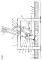
- the cutting device has a machine frame 1, into which a conveyor belt 2 conveys the extruded or calendered profile strips 3 coming from a cooling / conveying system (not shown) to be cut to specific lengths.
- the cut is carried out with a rotating knife 4, which engages in a groove of a strip 5 serving as a cutting counter bearing.
- the supplied profile strip 3 is used for the cut by stopping the conveyor belt 2 and stopping a pressure roller 6 for the cut stopped.
- the cut profile belt piece 7 is transported away from the conveyor belt 8.
- the knife 4 is fixed on the knife shaft 9, which is mounted in the bearing housing 10, which is fixedly attached to the gear housing 11.
- This gear housing 11 is freely movable back and forth on the drive shaft 12.
- Reversing links 13 determine the end points of the movement of the gear housing 11 on the drive shaft 12.
- This drive shaft is mounted in bearings 14 and driven by a motor 15.
- the rotating knife 4 is driven by a motor 16 via an articulated shaft 17 which is designed to be telescopic. All these components are carried by the rocker 18.
- the motors 15 and 16 are fixedly mounted on the rocker 18, as are the bearings 14 for the drive shaft 12.
- a guide rail 19 is fixedly mounted on the rocker 18.
- the gear housing 11 is displaceable along this guide rail 19, the guide rail 19 serves to move the gear housing 11 back and forth without twisting.
- Fixed, but adjustable to certain distances from each other, the reversing links 13 are attached to the rocker 18. You determine the path length covered by the gear housing 11. When cutting wide protector strips, these reversing links 13 are set further apart than when cutting narrow side wall strips.
- the rocker 18 can be pivoted about the axis 20. It will be between one Cutting position and a return position moved by means of the pneumatic servo drive 21 and held in the end positions by stops 22, 23, the stop 22 determining the cutting position, the stop 23 the return stroke position.
- the transmission housing 11 is penetrated by the drive shaft 12. Inside the transmission housing 11 there are three ball bearings 24, 25 arranged eccentrically to the axis of the drive shaft 12, with a spherical inner ring which has a larger inner diameter than the outer diameter of the drive shaft and is pressed against the drive shaft 12 under the pressure of disc springs.
- the ball bearings 24, 25 are mounted in pivotable brackets 26. Depending on the set swivel angle as a function of the speed of the drive shaft 12, a lateral force component is exerted on the transmission housing 11 relative to the shaft 12, which initiates the movement and carries it out precisely.
- the pivoting angle is set for the three ball bearings 24, 25 by means of a common adjustment plate 27 which has openings for pins 28 attached to the brackets 26. The position of this setting plate 27 is set by the reversing link 13, which pushes the setting plate 27 into its two end positions.
- the drive motor 16 for the knife shaft 9 is fixedly mounted on the holder 32 on the machine frame 1.
- the cross feed device in the form of the rolling ring drive with the gear housing 11, the drive shaft 12 and the motor 15 are built on the carrier 29, which is designed as a carriage and with wheels 33 on guide rails 30 in the direction indicated by a double arrow with the help of the servo motor 21, which by a pneumatic piston-cylinder unit is formed, is displaceable.
- the carriage 29 is moved with the aid of the servo motor 21.
- the carrier 29 is formed by a carriage which is supported on the vertically arranged guide rail 30 via wheels 33 and is moved by means of the servo motor 21 in order to pull up the return stroke for the return movement of the knife 4 in the upper position to be able to perform without touching the strip 3 to be cut.
- the parts of the transverse movement device 10, 11, 12 are attached to the slide serving as the carrier 29.
- the bearing housing 10 for the knife shaft 9 is firmly attached to the gear housing 11 of the transverse feed device.
- links 34, 35 are provided for carrying the transverse feed device 10, 11, 12, the upper link 34 being a double-arm link, on one arm of which the servo motor 21 engages.
Landscapes
- Engineering & Computer Science (AREA)
- Mechanical Engineering (AREA)
- Life Sciences & Earth Sciences (AREA)
- Forests & Forestry (AREA)
- Textile Engineering (AREA)
- Tyre Moulding (AREA)
- Processing And Handling Of Plastics And Other Materials For Molding In General (AREA)
- Nonmetal Cutting Devices (AREA)
Claims (9)
- Dispositif de coupe pour couper une bande profilée (3) formée par extrusion et/ou calandrage de mélanges de caoutchouc, dont le trajet de transport (2) est organisé pour un mouvement interrompu pour l'opération de coupe, constitué par une lame circulaire (4), fixée sur un arbre (9) de lame, entraînée par un moteur (16) avec interposition d'un arbre flexible (17), et un dispositif de déplacement transversal (11, 12) qui déplace la lame (4) alternativement entre deux positions extrêmes pouvant être prédéterminées, l'arbre (9) de lame et son palier étant agencés sur une monture commune (18, 29) qui peut être déplacée en translation et/ou en oscillation pour déplacer la lame (4) entre une position de coupe et une position de retour dans laquelle la lame (4) se trouve en dehors de la trajectoire de la bande profilée (3), de sorte que, pendant la course de retour, la lame (4) peut être mise en mouvement transversal par le dispositif de déplacement transversal (11, 12) sur une trajectoire située plus haut que pendant la course de coupe,
caractérisé
en ce que le dispositif de déplacement transversal (11, 12) est agencé sur la monture (18, 29) et la monture (18, 29) peut être mise en mouvement d'oscillation autour d'un arbre (20) relié rigidement au bâti (1) de la machine et/ou en translation le long d'un guide monté rigidement sur le bâti (1) de la machine,
en ce que le dispositif de déplacement transversal (11, 12) est une transmission à courroie roulante dont l'arbre d'entraînement (12) est monté rotatif mais non déplaçable en translation dans deux paliers (14) fixés à la monture (18, 29), en ce que l'arbre (9) de la lame est monté mobile en rotation mais non déplaçable en translation dans ou sur un boîtier de palier relié rigidement au boîtier (11) de la transmission à couronne roulante,
et en ce qu'un dispositif (17) de transmission de force, solidaire en rotation, est interposé entre l'arbre (9) de la lame et l'arbre du moteur (16) qui ne peut pas être déplacé par le dispositif de déplacement transversal (11, 12), ce dispositif de transmission de force admettant les mouvements relatifs entre l'arbre (9) de la lame et l'arbre du moteur (16) qui se produisent pendant le fonctionnement et qui sont provoqués par le déplacement du dispositif de déplacement transversal (11, 12). - Dispositif de coupe selon la revendication 1,
caractérisé
en ce que le dispositif de déplacement transversal (11, 12) et le moteur (16) sont agencés sur la monture (18) qui est réalisée sous la forme d'un balancier pouvant osciller autour d'un axe horizontal (20). - Dispositif de coupe selon la revendication 2,
caractérisé
en ce que des coulisses d'inversion (13) pour la transmission à courroie roulante (11, 12) sont fixées sur le balancier (18) avec possibilité de réglage sur certaines positions pouvant être prédéterminées. - Dispositif de coupe selon la revendication 1,
caractérisé
en ce que l'arbre (9) de la lame, l'arbre articulé (17), réglable en longueur et l'arbre du moteur (16) sont contenus dans un plan commun. - Dispositif de coupe selon la revendication 1,
caractérisé
en ce que l'arbre (9) de la lame, son palier (10) et le dispositif de déplacement transversal (11, 12) sont agencés sur une monture constituée par un support commun (29) à l'aide de laquelle la lame (4) peut être éloignée de sa zone de coupe de la bande (3) à couper par un mouvement de translation, parallèlement à elle-même. - Dispositif de coupe selon la revendication 5,
caractérisé
en ce que le support (29) peut être éloigné de la zone de coupe de la bande (3) à couper par un mouvement de translation dans un plan, parallèlement à la lame (4) ou transversalement à l'arbre (9) de la lame. - Dispositif de coupe selon la revendication 5,
caractérisé
en ce que des coulisses d'inversion (13) pour la transmission à courroie roulante (11, 12) sont agencées sur le support (29) pour se placer dans certaines positions pouvant être prédéterminées. - Dispositif de coupe selon la revendication 5,
caractérisé par
des rails de guidage (30) fixés dans le bâti, servant à guider le support (29) mobile en translation. - Dispositif de coupe selon la revendication 5,
caractérisé
par des biellettes (31) disposées dans un parallélogramme, dont une extrémité est articulée sur le bâti (1) et l'autre extrémité sur le support (29).
Applications Claiming Priority (2)
| Application Number | Priority Date | Filing Date | Title |
|---|---|---|---|
| DE4116971 | 1991-05-24 | ||
| DE4116971A DE4116971C2 (de) | 1991-05-24 | 1991-05-24 | Schneidvorrichtung für einen aus Kautschukmischungen geformten Profilstreifen |
Publications (2)
| Publication Number | Publication Date |
|---|---|
| EP0518043A1 EP0518043A1 (fr) | 1992-12-16 |
| EP0518043B1 true EP0518043B1 (fr) | 1995-11-02 |
Family
ID=6432335
Family Applications (1)
| Application Number | Title | Priority Date | Filing Date |
|---|---|---|---|
| EP92107358A Expired - Lifetime EP0518043B1 (fr) | 1991-05-24 | 1992-04-30 | Dispositif pour la coupe de bandes profilées en caoutchouc |
Country Status (7)
| Country | Link |
|---|---|
| EP (1) | EP0518043B1 (fr) |
| JP (1) | JPH05177583A (fr) |
| KR (1) | KR920021273A (fr) |
| CA (1) | CA2069391A1 (fr) |
| CZ (1) | CZ281479B6 (fr) |
| DE (2) | DE4116971C2 (fr) |
| HU (1) | HUT62826A (fr) |
Families Citing this family (7)
| Publication number | Priority date | Publication date | Assignee | Title |
|---|---|---|---|---|
| DE19654408A1 (de) * | 1996-12-24 | 1998-06-25 | Continental Ag | Verfahren zum Ablängen eines unvulkanisierten Kautschukprofiles mittels einer Schneide |
| DE19914194C2 (de) * | 1999-03-24 | 2001-09-27 | Mannesmann Ag | Schneidmaschine mit rotierend angetriebenem Schneidmesser |
| GB201303178D0 (en) * | 2013-02-22 | 2013-04-10 | Uhing Joachim Gmbh & Co Kg | Reversal mechanism for a rolling ring drive |
| CN114471268B (zh) * | 2016-11-01 | 2024-05-24 | 生命科技股份有限公司 | 具有可垂直调整的混合元件的液体混合系统及其使用方法 |
| CN109465871B (zh) * | 2018-12-29 | 2024-02-09 | 湖南联创兴电子科技有限公司 | 一种pcb板在线切割装置 |
| CN110744739B (zh) * | 2019-10-28 | 2020-09-18 | 山东水星博惠汽车部件股份有限公司 | 一种汽车合成橡胶件混炼用自动化切胶装置 |
| CN119023369B (zh) * | 2024-10-23 | 2025-01-28 | 中国有色金属工业昆明勘察设计研究院有限公司 | 一种厚层生态基材冻涨融沉试验装置 |
Family Cites Families (8)
| Publication number | Priority date | Publication date | Assignee | Title |
|---|---|---|---|---|
| GB441648A (en) * | 1934-10-30 | 1936-01-23 | Dunlop Rubber Co | Apparatus for cutting strip or the like material |
| US2544241A (en) * | 1946-05-01 | 1951-03-06 | Goodrich Co B F | Apparatus for cutting material |
| US2550191A (en) * | 1947-03-12 | 1951-04-24 | Us Rubber Co | Automatic cutting device |
| US3072004A (en) * | 1959-07-31 | 1963-01-08 | Armstrong Rubber Co | Severing apparatus |
| DE1186209B (de) * | 1961-11-17 | 1965-01-28 | Continental Gummi Werke Ag | Schneidvorrichtung zum Ablaengen von Reifenlaufstreifen |
| DE1806747A1 (de) * | 1968-11-02 | 1970-05-21 | Schwermaschb Ernst Thaelmann V | Einrichtung zum Regeln der Geschwindigkeit der Traeger von Werkzeugen,Vorrichtungen u.dgl. |
| IT1198196B (it) * | 1986-11-28 | 1988-12-21 | Pirelli | Dispositivo atto a tagliare o rifilare bordi di tessuti gommati,muniti di elementi di rinforzo trasversali,a filo di uno di detti elementi di rinforzo |
| US4813319A (en) * | 1987-04-01 | 1989-03-21 | The Firestone Tire & Rubber Company | Method and apparatus for transversely cutting strips of deformable material |
-
1991
- 1991-05-24 DE DE4116971A patent/DE4116971C2/de not_active Expired - Fee Related
-
1992
- 1992-04-30 EP EP92107358A patent/EP0518043B1/fr not_active Expired - Lifetime
- 1992-04-30 DE DE59204173T patent/DE59204173D1/de not_active Expired - Fee Related
- 1992-05-19 KR KR1019920008417A patent/KR920021273A/ko not_active Withdrawn
- 1992-05-20 HU HU9201675A patent/HUT62826A/hu unknown
- 1992-05-22 CZ CS921550A patent/CZ281479B6/cs unknown
- 1992-05-22 JP JP4156011A patent/JPH05177583A/ja active Pending
- 1992-05-25 CA CA002069391A patent/CA2069391A1/fr not_active Abandoned
Also Published As
| Publication number | Publication date |
|---|---|
| CA2069391A1 (fr) | 1992-11-25 |
| DE59204173D1 (de) | 1995-12-07 |
| HUT62826A (en) | 1993-06-28 |
| JPH05177583A (ja) | 1993-07-20 |
| EP0518043A1 (fr) | 1992-12-16 |
| HU9201675D0 (en) | 1992-09-28 |
| DE4116971C2 (de) | 1996-07-25 |
| DE4116971A1 (de) | 1992-11-26 |
| CS155092A3 (en) | 1992-12-16 |
| CZ281479B6 (cs) | 1996-10-16 |
| KR920021273A (ko) | 1992-12-18 |
Similar Documents
| Publication | Publication Date | Title |
|---|---|---|
| DE2252047C3 (de) | Vorrichtung zum Zerschneiden eines kontinuierlich bewegten Bandes aus plastisch verformbarem Material in einzelne Formstücke, beispielsweise Betonziegel | |
| EP0107056A2 (fr) | Trancheuse | |
| DE3715229A1 (de) | Schneidkopf mit schneidmesser zum schneiden von flachmaterial | |
| EP0085387A2 (fr) | Appareil pour couper et rainurer des bandes en mouvement, en particulier des bandes de papier | |
| DE3416664C2 (de) | Einrichtung zum Steuern der Schneidgeschwindigkeit des Sägeblattes einer Bandsägemaschine | |
| DE3745008C2 (fr) | ||
| EP0518043B1 (fr) | Dispositif pour la coupe de bandes profilées en caoutchouc | |
| DE2318970C3 (de) | Fliegende Schere oder Stanze für laufendes Material | |
| DE3632779C2 (fr) | ||
| CH658205A5 (de) | Maschine zum kontinuierlichen abscheren und kaltstauchen des abgescherten teils, insbesondere ausgehend von drahtmaterial. | |
| DE4419963C1 (de) | Kreuzbandschleifmaschine zum beiderseitigen Anfasen des Randes von Glasplatten | |
| DE2546000C3 (de) | Vorschubeinrichtung für Holzstämme bei einer Entrindungsmaschine | |
| EP3294494B1 (fr) | Dipsositif de finition par courroie | |
| CH640771A5 (de) | Verfahren zum durchtrennen von beschichtetem plattenmaterial sowie einrichtung zu seiner durchfuehrung. | |
| DE3219358C2 (fr) | ||
| DE3436576A1 (de) | Beschickungs- und entnahmevorrichtung, insbesondere an pressen | |
| DE102021103849A1 (de) | Aufschneide-Maschine sowie Betriebs-Verfahren hierfür zum Verbessern des ziehenden Schnittes | |
| DE1928820B1 (de) | Vorrichtung zum Bearbeiten von Tafelglas | |
| EP0620072A1 (fr) | Méthode et dispositif pour l'usinage de tôles minces | |
| DE3048738C2 (de) | Vorschubeinrichtung zum intermittierenden Drehen eines Kreissägeblattes | |
| DE3942191A1 (de) | Trennvorrichtung fuer biegemaschinen | |
| EP0058369A2 (fr) | Dispositif d'avance pour les machines-outils pour l'usinage du bois | |
| DE4235240C2 (de) | Verfahren zur Herstellung und Bearbeitung paralleler Gehrungen an den beiden Stirnflächen langgestreckter Hölzer und Doppelendprofiler zur Durchführung dieses Verfahrens | |
| EP1029640A2 (fr) | Dispositif pour opérer de façon transversale sur une couche de matériau, en particulier pour découper transversalement du papier | |
| DE2012361B1 (de) | Kreismesserschneidemaschine |
Legal Events
| Date | Code | Title | Description |
|---|---|---|---|
| PUAI | Public reference made under article 153(3) epc to a published international application that has entered the european phase |
Free format text: ORIGINAL CODE: 0009012 |
|
| AK | Designated contracting states |
Kind code of ref document: A1 Designated state(s): CH DE FR GB IT LI |
|
| 17P | Request for examination filed |
Effective date: 19930111 |
|
| 17Q | First examination report despatched |
Effective date: 19940913 |
|
| GRAA | (expected) grant |
Free format text: ORIGINAL CODE: 0009210 |
|
| ITF | It: translation for a ep patent filed | ||
| AK | Designated contracting states |
Kind code of ref document: B1 Designated state(s): CH DE FR GB IT LI |
|
| REF | Corresponds to: |
Ref document number: 59204173 Country of ref document: DE Date of ref document: 19951207 |
|
| ET | Fr: translation filed | ||
| REG | Reference to a national code |
Ref country code: CH Ref legal event code: NV Representative=s name: DR. KURT F. BUECHEL PATENTANWALT |
|
| GBT | Gb: translation of ep patent filed (gb section 77(6)(a)/1977) |
Effective date: 19960122 |
|
| PGFP | Annual fee paid to national office [announced via postgrant information from national office to epo] |
Ref country code: DE Payment date: 19960419 Year of fee payment: 5 |
|
| PGFP | Annual fee paid to national office [announced via postgrant information from national office to epo] |
Ref country code: GB Payment date: 19960423 Year of fee payment: 5 |
|
| PGFP | Annual fee paid to national office [announced via postgrant information from national office to epo] |
Ref country code: FR Payment date: 19960426 Year of fee payment: 5 |
|
| PG25 | Lapsed in a contracting state [announced via postgrant information from national office to epo] |
Ref country code: LI Effective date: 19960430 Ref country code: CH Effective date: 19960430 |
|
| PLBE | No opposition filed within time limit |
Free format text: ORIGINAL CODE: 0009261 |
|
| STAA | Information on the status of an ep patent application or granted ep patent |
Free format text: STATUS: NO OPPOSITION FILED WITHIN TIME LIMIT |
|
| 26N | No opposition filed | ||
| REG | Reference to a national code |
Ref country code: CH Ref legal event code: PL |
|
| PG25 | Lapsed in a contracting state [announced via postgrant information from national office to epo] |
Ref country code: GB Effective date: 19970430 |
|
| GBPC | Gb: european patent ceased through non-payment of renewal fee |
Effective date: 19970430 |
|
| PG25 | Lapsed in a contracting state [announced via postgrant information from national office to epo] |
Ref country code: FR Free format text: LAPSE BECAUSE OF NON-PAYMENT OF DUE FEES Effective date: 19971231 |
|
| PG25 | Lapsed in a contracting state [announced via postgrant information from national office to epo] |
Ref country code: DE Free format text: LAPSE BECAUSE OF NON-PAYMENT OF DUE FEES Effective date: 19980101 |
|
| REG | Reference to a national code |
Ref country code: FR Ref legal event code: ST |
|
| PG25 | Lapsed in a contracting state [announced via postgrant information from national office to epo] |
Ref country code: IT Free format text: LAPSE BECAUSE OF NON-PAYMENT OF DUE FEES;WARNING: LAPSES OF ITALIAN PATENTS WITH EFFECTIVE DATE BEFORE 2007 MAY HAVE OCCURRED AT ANY TIME BEFORE 2007. THE CORRECT EFFECTIVE DATE MAY BE DIFFERENT FROM THE ONE RECORDED. Effective date: 20050430 |