EP0518318B1 - Procédé et appareil pour la production d'une fibre optique revêtue hermétiquement - Google Patents
Procédé et appareil pour la production d'une fibre optique revêtue hermétiquement Download PDFInfo
- Publication number
- EP0518318B1 EP0518318B1 EP92109826A EP92109826A EP0518318B1 EP 0518318 B1 EP0518318 B1 EP 0518318B1 EP 92109826 A EP92109826 A EP 92109826A EP 92109826 A EP92109826 A EP 92109826A EP 0518318 B1 EP0518318 B1 EP 0518318B1
- Authority
- EP
- European Patent Office
- Prior art keywords
- liquid
- reactor vessel
- wall
- fiber
- inner chamber
- Prior art date
- Legal status (The legal status is an assumption and is not a legal conclusion. Google has not performed a legal analysis and makes no representation as to the accuracy of the status listed.)
- Expired - Lifetime
Links
- 238000000034 method Methods 0.000 title claims description 23
- 239000013307 optical fiber Substances 0.000 title claims description 20
- 238000004519 manufacturing process Methods 0.000 title claims description 9
- 239000007788 liquid Substances 0.000 claims description 105
- 239000007789 gas Substances 0.000 claims description 36
- 239000002245 particle Substances 0.000 claims description 32
- 239000000835 fiber Substances 0.000 claims description 30
- 239000000376 reactant Substances 0.000 claims description 20
- 238000000576 coating method Methods 0.000 claims description 18
- 239000002699 waste material Substances 0.000 claims description 17
- 239000011248 coating agent Substances 0.000 claims description 16
- 239000002912 waste gas Substances 0.000 claims description 14
- 238000006243 chemical reaction Methods 0.000 claims description 10
- 239000000463 material Substances 0.000 claims description 5
- 238000005229 chemical vapour deposition Methods 0.000 claims description 3
- 238000011144 upstream manufacturing Methods 0.000 claims 4
- 238000007599 discharging Methods 0.000 claims 2
- 239000011247 coating layer Substances 0.000 claims 1
- 230000008018 melting Effects 0.000 claims 1
- 238000002844 melting Methods 0.000 claims 1
- 230000003287 optical effect Effects 0.000 claims 1
- 238000002230 thermal chemical vapour deposition Methods 0.000 claims 1
- 239000007787 solid Substances 0.000 description 16
- OKTJSMMVPCPJKN-UHFFFAOYSA-N Carbon Chemical compound [C] OKTJSMMVPCPJKN-UHFFFAOYSA-N 0.000 description 12
- 229910052799 carbon Inorganic materials 0.000 description 12
- 239000003599 detergent Substances 0.000 description 9
- XLYOFNOQVPJJNP-UHFFFAOYSA-N water Substances O XLYOFNOQVPJJNP-UHFFFAOYSA-N 0.000 description 9
- HEDRZPFGACZZDS-UHFFFAOYSA-N Chloroform Chemical compound ClC(Cl)Cl HEDRZPFGACZZDS-UHFFFAOYSA-N 0.000 description 6
- 239000003365 glass fiber Substances 0.000 description 3
- 239000001257 hydrogen Substances 0.000 description 3
- 229910052739 hydrogen Inorganic materials 0.000 description 3
- YCKRFDGAMUMZLT-UHFFFAOYSA-N Fluorine atom Chemical compound [F] YCKRFDGAMUMZLT-UHFFFAOYSA-N 0.000 description 2
- UFHFLCQGNIYNRP-UHFFFAOYSA-N Hydrogen Chemical compound [H][H] UFHFLCQGNIYNRP-UHFFFAOYSA-N 0.000 description 2
- VYPSYNLAJGMNEJ-UHFFFAOYSA-N Silicium dioxide Chemical compound O=[Si]=O VYPSYNLAJGMNEJ-UHFFFAOYSA-N 0.000 description 2
- GWEVSGVZZGPLCZ-UHFFFAOYSA-N Titan oxide Chemical compound O=[Ti]=O GWEVSGVZZGPLCZ-UHFFFAOYSA-N 0.000 description 2
- 239000006227 byproduct Substances 0.000 description 2
- 230000000694 effects Effects 0.000 description 2
- 239000004744 fabric Substances 0.000 description 2
- 238000012681 fiber drawing Methods 0.000 description 2
- 229910052731 fluorine Inorganic materials 0.000 description 2
- 239000011737 fluorine Substances 0.000 description 2
- 230000036961 partial effect Effects 0.000 description 2
- 239000000047 product Substances 0.000 description 2
- 230000001681 protective effect Effects 0.000 description 2
- 229920002545 silicone oil Polymers 0.000 description 2
- 239000012808 vapor phase Substances 0.000 description 2
- IJGRMHOSHXDMSA-UHFFFAOYSA-N Atomic nitrogen Chemical compound N#N IJGRMHOSHXDMSA-UHFFFAOYSA-N 0.000 description 1
- ZAMOUSCENKQFHK-UHFFFAOYSA-N Chlorine atom Chemical compound [Cl] ZAMOUSCENKQFHK-UHFFFAOYSA-N 0.000 description 1
- VEXZGXHMUGYJMC-UHFFFAOYSA-N Hydrochloric acid Chemical compound Cl VEXZGXHMUGYJMC-UHFFFAOYSA-N 0.000 description 1
- 229910052581 Si3N4 Inorganic materials 0.000 description 1
- 229910034327 TiC Inorganic materials 0.000 description 1
- ATJFFYVFTNAWJD-UHFFFAOYSA-N Tin Chemical compound [Sn] ATJFFYVFTNAWJD-UHFFFAOYSA-N 0.000 description 1
- 239000002253 acid Substances 0.000 description 1
- 239000012190 activator Substances 0.000 description 1
- 230000002411 adverse Effects 0.000 description 1
- 229910045601 alloy Inorganic materials 0.000 description 1
- 239000000956 alloy Substances 0.000 description 1
- 230000015572 biosynthetic process Effects 0.000 description 1
- 238000009835 boiling Methods 0.000 description 1
- 239000012159 carrier gas Substances 0.000 description 1
- 239000000460 chlorine Substances 0.000 description 1
- 229910052801 chlorine Inorganic materials 0.000 description 1
- 238000010276 construction Methods 0.000 description 1
- 238000001816 cooling Methods 0.000 description 1
- 238000000151 deposition Methods 0.000 description 1
- 230000008021 deposition Effects 0.000 description 1
- 229910001873 dinitrogen Inorganic materials 0.000 description 1
- 238000006073 displacement reaction Methods 0.000 description 1
- 230000009977 dual effect Effects 0.000 description 1
- 238000005516 engineering process Methods 0.000 description 1
- 238000002474 experimental method Methods 0.000 description 1
- 238000001914 filtration Methods 0.000 description 1
- 239000005338 frosted glass Substances 0.000 description 1
- 238000010438 heat treatment Methods 0.000 description 1
- 229910010272 inorganic material Inorganic materials 0.000 description 1
- 239000011147 inorganic material Substances 0.000 description 1
- 230000000670 limiting effect Effects 0.000 description 1
- 239000000314 lubricant Substances 0.000 description 1
- 229910052751 metal Inorganic materials 0.000 description 1
- 239000002184 metal Substances 0.000 description 1
- 150000002739 metals Chemical class 0.000 description 1
- 229910003465 moissanite Inorganic materials 0.000 description 1
- 230000007935 neutral effect Effects 0.000 description 1
- 239000003921 oil Substances 0.000 description 1
- 239000012071 phase Substances 0.000 description 1
- 230000000704 physical effect Effects 0.000 description 1
- 229920001296 polysiloxane Polymers 0.000 description 1
- 239000010453 quartz Substances 0.000 description 1
- 230000002829 reductive effect Effects 0.000 description 1
- 230000000717 retained effect Effects 0.000 description 1
- 229910010271 silicon carbide Inorganic materials 0.000 description 1
- 239000000126 substance Substances 0.000 description 1
- 238000001089 thermophoresis Methods 0.000 description 1
- 229910052718 tin Inorganic materials 0.000 description 1
Images


Classifications
-
- G—PHYSICS
- G02—OPTICS
- G02B—OPTICAL ELEMENTS, SYSTEMS OR APPARATUS
- G02B6/00—Light guides; Structural details of arrangements comprising light guides and other optical elements, e.g. couplings
- G02B6/44—Mechanical structures for providing tensile strength and external protection for fibres, e.g. optical transmission cables
-
- C—CHEMISTRY; METALLURGY
- C23—COATING METALLIC MATERIAL; COATING MATERIAL WITH METALLIC MATERIAL; CHEMICAL SURFACE TREATMENT; DIFFUSION TREATMENT OF METALLIC MATERIAL; COATING BY VACUUM EVAPORATION, BY SPUTTERING, BY ION IMPLANTATION OR BY CHEMICAL VAPOUR DEPOSITION, IN GENERAL; INHIBITING CORROSION OF METALLIC MATERIAL OR INCRUSTATION IN GENERAL
- C23C—COATING METALLIC MATERIAL; COATING MATERIAL WITH METALLIC MATERIAL; SURFACE TREATMENT OF METALLIC MATERIAL BY DIFFUSION INTO THE SURFACE, BY CHEMICAL CONVERSION OR SUBSTITUTION; COATING BY VACUUM EVAPORATION, BY SPUTTERING, BY ION IMPLANTATION OR BY CHEMICAL VAPOUR DEPOSITION, IN GENERAL
- C23C16/00—Chemical coating by decomposition of gaseous compounds, without leaving reaction products of surface material in the coating, i.e. chemical vapour deposition [CVD] processes
- C23C16/44—Chemical coating by decomposition of gaseous compounds, without leaving reaction products of surface material in the coating, i.e. chemical vapour deposition [CVD] processes characterised by the method of coating
- C23C16/54—Apparatus specially adapted for continuous coating
- C23C16/545—Apparatus specially adapted for continuous coating for coating elongated substrates
-
- C—CHEMISTRY; METALLURGY
- C03—GLASS; MINERAL OR SLAG WOOL
- C03C—CHEMICAL COMPOSITION OF GLASSES, GLAZES OR VITREOUS ENAMELS; SURFACE TREATMENT OF GLASS; SURFACE TREATMENT OF FIBRES OR FILAMENTS MADE FROM GLASS, MINERALS OR SLAGS; JOINING GLASS TO GLASS OR OTHER MATERIALS
- C03C25/00—Surface treatment of fibres or filaments made from glass, minerals or slags
- C03C25/10—Coating
- C03C25/104—Coating to obtain optical fibres
- C03C25/106—Single coatings
- C03C25/1061—Inorganic coatings
- C03C25/1062—Carbon
-
- C—CHEMISTRY; METALLURGY
- C03—GLASS; MINERAL OR SLAG WOOL
- C03C—CHEMICAL COMPOSITION OF GLASSES, GLAZES OR VITREOUS ENAMELS; SURFACE TREATMENT OF GLASS; SURFACE TREATMENT OF FIBRES OR FILAMENTS MADE FROM GLASS, MINERALS OR SLAGS; JOINING GLASS TO GLASS OR OTHER MATERIALS
- C03C25/00—Surface treatment of fibres or filaments made from glass, minerals or slags
- C03C25/10—Coating
- C03C25/12—General methods of coating; Devices therefor
- C03C25/22—Deposition from the vapour phase
- C03C25/223—Deposition from the vapour phase by chemical vapour deposition or pyrolysis
-
- G—PHYSICS
- G02—OPTICS
- G02B—OPTICAL ELEMENTS, SYSTEMS OR APPARATUS
- G02B6/00—Light guides; Structural details of arrangements comprising light guides and other optical elements, e.g. couplings
- G02B6/02—Optical fibres with cladding with or without a coating
Definitions
- the present invention relates to a method and an apparatus for manufacturing a hermetically coated optical fiber, and more particularly to such a method and an apparatus suitable for mass production.
- a hermetically coated optical fiber is an effective product for preventing ambient gases such as water, hydrogen etc. from adhering to the optical fiber or permeating through the optical fiber.
- inorganic materials such as metals including alloys and carbon etc. are used as coating materials.
- carbon coating is one of the most excellent ones in term of its chemical stability and fine grained structure etc. and one of the coating processes is a chemical vapor deposition (CVD) process in which reactant gas reacts chemically to deposit coating material on the optical fiber surface, this process being advantageous in terms of coating speed and quality of the layer.
- CVD chemical vapor deposition
- the reactor vessels typically have a seal gas inlet port and a reactant gas inlet port at their upper end; and a waste gas discharge port at their lower end.
- a formed fiber of high temperature is hermetically coated thermo-chemically in the reactor vessel between the reactant gas inlet port and the waste gas discharge port.
- an optical fiber is drawn from a preform in a draw furnace, before it is provided with a hermetic coating.
- a sufficient temperature (about 1300 °C) is necessary for the formation of the coating particles and to ensure that these particles are maintained at the fiber surface without the need for additional heating means.
- the present invention provides a method of manufacturing a hermetically coated optical fiber as defined in the accompanying Claims 1 to 5; and an apparatus for manufacturing a hermetically coated optical fiber as defined in the accompanying Claims 6 to 10.
- a reactor vessel 2 is provided with an upper seal gas inlet port 3, a reactant gas inlet port 4 (reactant gas is supplied to the reactor vessel from 4 directions), a waste gas discharge port 6 and a lower seal gas inlet port 5 respectively in this order from the upper to the lower extent of the reactor vessel 2.
- the reactor vessel 2 is furnished with a liquid inlet port 7 for introducing a liquid 13 which prevents solid particles from sticking to an inner wall of the reactor vessel and/or removes solid particle layer deposited on the inner wall of the vessel, and a reservoir 8 for keeping the liquid 13, at the upper part of the reactor vessel.
- the reactor vessel 2 is also furnished with a waste liquid discharge port 9 and a waste liquid treating apparatus 12 at the lower part thereof. Those elements are made of quartz glass or the like.
- the liquid 13 is supplied to the reservoir 8 through the liquid inlet port 7 continuously or intermittently at an optional interval.
- the accumulated liquid overflows a weir 81 to the inner wall of the reactor vessel 2, uniformly along the circumference of the inner wall, and the liquid 13 flows down on the inner wall.
- the liquid 13 takes in particles formed in a vapor phase process which are going to stick to the inner wall of the reactor vessel, and quickly discharges the particles out of the reactor vessel.
- the particles are supposed to be flushed away after the particles once deposited to form a solid particle layer.
- the weir 81 is formed as horizontally as possible so that the liquid 13 overflows the weir supplied uniformly along all over the circumference of the inner wall of the reactor.
- the top ridge of the weir may be indented as saw teeth, to distribute the liquid uniformly.
- a plurality of small holes may be provided circumferentially at the bottom of the weir 81, through which the liquid 13 can flow out to be supplied to the inner wall.
- the liquid introduced through the liquid inlet port 7 must flow out through the small holes first and there after the surplus overflows the weir 81. Even when the supply of the liquid through the inlet port 7 is stopped, the liquid retained in the reservoir 8 is continued to flow out to the inner wall of the reactor vessel 2 through the small holes for a while.
- the waste liquid is discharged through the waste liquid discharge port 9 to the waste liquid treating apparatus wherein the waste liquid is treated.
- the liquid reclaimed in the waste liquid treating apparatus 12 may be recycled, or it is possible to construct a circulating system.
- An exhaust or waste gas is evacuated after it is discharged through the waste gas discharge port 6 to the waste gas treating apparatus 11 and is treated there.
- a protective pipe 10 should preferably be furnished for the fiber not to come in contact with the waste.
- Reference numeral 20 denotes the hermetically coated fiber.
- liquid flowing down a vertical wall is apt to gradually gather into a few stripes of stream, as it goes down. It is because the flow speed becomes higher and the thickness of liquid flow becomes too thin to keep a flat layer of flow, and surface tension also acts to make the liquid surface as small as possible.
- Solid particles generated in a gas phase are easy to deposit on the inner wall where the reactant gas stagnates on the reactor vessel.
- the bottom part of the reactor vessel is a place where the gas tends to stagnate, and the liquid stream layer tends to be thin, and solid particles are apt to be deposited in quantity.
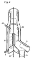
- a second liquid inlet port 85 and a second reservoir 86 may be furnished at the bottom part of the reactor vessel as shown in FIG. 4.
- liquid inlet holes may be furnished in the wall of the reactor vessel.
- FIG. 2 An apparatus as shown in FIG. 2 is effective.
- An inner pipe of a reactor vessel is denoted by reference numeral 21 and an external pipe is by 22.
- the inner pipe is provided with a plurality of openings, which are preferably small to prevent liquid from splashing to the fiber.
- This embodiment is especially effective when the liquid flows intermittently and the flow rate is high, consequently many splashes are easy to be generated.
- a small amount of liquid is supplied continuously to the inner pipe, although the gas will not stagnate in the inner pipe and only a small amount of solid particles would deposit on it even without the liquid supply.
- the reservoir 8 is provided with holes of about 0.5 to 3 mm in diameter and a few to more than ten in number at the bottom, along the inner wall of the reactor vessel.
- the liquid supplied through the holes flows uniformly on the inner wall of the reactor vessel.
- the liquid may overflow the weir 81.
- a protective pipe 10 is provided for preventing the liquid from coming in contact with the optical fiber and also forming a reservoir.
- a liquid with relatively low viscosity may be used when the liquid is supplied intermittently.
- solid particle layer which deposited once on the inner wall is flushed away and sometimes a rigidly sticked layer could not be removed.
- the sticked layer is at most a few mm thick and is not very big trouble.
- a liquid with relatively high viscosity may preferably be used to prevent the liquid from splashing regularly.
- the inner wall of the reactor vessel is always covered with the liquid and solid particles could not stick to the inner wall, and are effectively evacuated.
- a liquid with low viscosity can also be used even when supplied continuously, although the supply amount may be somewhat increased.
- Water is one of the suitable liquids for the present invention. Water is most easily handled and very cheap, and can be treated easily after flowing to waste. And when an interface activator such as a kitchen or industrial detergent on the market (for example, SHOKO Co.'s Kurihn Ehsu S (Trade Mark)(Clean Ace S), SHARP SYSTEM PRODUCTS Co.'s Ekitai Senjohzai M-251L (Trade Mark)(Liquid Detergent M-251L), YUHO CHEMICAL Co.'s Kurihn Ruhm You Senjohzai CC-85(Trade Mark)(DETERGENT FOR CLEAN ROOM CC-85), IUCHI Co.'s Pyua Sofuto PS(Trade Mark)(PURE SOFT PS), IUCHI Co.'s Senzai Burukurihn 90, Burukurihn 70, Resukon Ls (Trade Mark)(DETERGENT Blue Clean 90, Blue Clean 70, Ls Con Ls
- low viscosity liquids there are fluorine family inert liquids, and the like on the market (for example, Sumitomo 3M Co.'s Furorinahto (FLUORINERT)(Registered Trade Mark)).
- silicone oil family for example, Toshiba's SILICONE OILS of TSF 458, 451 series, 405 and 431, and YF33 (Trade Mark)can be adopted depending on the purpose, since one with preferred viscosity can be easily obtained in a wide range (for example a viscosity of 10 CST to 500000 CST is available for TSF 451 series).
- the liquid should be preferably as inert as possible to the reactant gas, but also it should be of no trouble for the characteristics of the product.
- the inner wall had better be as hydrophilic as possible to be wetted by the liquid. Then the inner wall of the reactor vessel may be treated to be hydrophilic.
- the inner wall can be hydrophilic or easy to be wetted by being of frosted glass, lined with glass fibers or glass fiber cloth and the like or scored with vertical stripes.
- the glass fiber cloth may preferably be woven using fibers of hundred to several hundreds micron-meter in diameter.
- the liquid should be basically as inert as possible to the reactant gas, but on the contrary alkaline liquid sometimes improves the process in case that a by-product from reaction is acid. It is because the by-product reacts to the liquid, that is, the liquid plays a role of waste gas treatment.
- reactant gases are C 2 H 4 + 2CHCl 3
- the generated hydrogen chloride (HCl) gas is absorbed by the liquid, resulting in accelerating the reaction. Consequently, a yield rate per unit of reactant gas is improved and consumption of the reactant gas can be reduced.
- Examples of alkaline liquid are aforementioned Liquid Detergent M-251L, DETERGENT FOR CLEAN ROOM CC-85, PURE SOFT PS, DETERGENT Blue Clean 90, Blue Clean 70, and Ls Con Ls.
- thermo-controller 90 Further by flowing a liquid temperature-controlled by a thermo-controller 90, or thermally controlling the reactor vessel to cool the reactor vessel to decrease the temperature of a gas, the generation of the particle can be suppressed.
- the temperature gradient is caused between a high temperature optical fiber and a low temperature reactor vessel and as the result the particles generated in the reactor vessel have tendency to approach the inner wall of the reactor vessel by Thermophoresis effect caused by the temperature gradient. Therefore, the attack to the optical fiber can be prevented.
- This example 1 was obtained by a method according to the prior art. With reactant gases of C 2 H 4 and CHCl 3 , and a CHCl 3 carrier gas of He, a quartz fiber was coated with carbon. Nitrogen gas N 2 was used as a upper seal gas, and air as a lower seal gas. Respective amounts of gases were set at as the following. C 2 H 4 100 cc/min CHCl 3 140 cc/min Upper seal gas 3.0 liter/min Lower seal gas 8.0 liter/min Fiber drawing speed 200 m/min.
- the fiber was coated about 60 km in length for about 5 hours.
- This example 2 was obtained by a method according to the present invention.
- a fiber was drawn and carbon-coated in the same conditions as in Example 1, in the reaction apparatus as shown in FIG. 1 using a fluorine family inert liquid without hydrogen and chlorine as the liquid.
- the liquid has kinetic viscosity of 13 cSt at ambient temperature and boiling temperature of about 200 degrees Celsius.
- the liquid was supplied intermittently at flow rate of 300 cc/min for one minute every 10 minutes. This ten minute cycle was repeated.
- the waste liquid was treated in the waste liquid treating apparatus 12, wherein filtering process was included.
- the treated liquid was recycled to the reactor vessel. Under the above described conditions, the fiber coating was continued for about 8 hours and about 100 km in length. Only a little particles remained in the reactor vessel after the operation, and a further coating operation had been possible.
- This example 3 was obtained by a method according to the present invention.
- a fiber was drawn and carbon-coated in the same conditions as in Test 2, except that the liquid was silicone family oil with kinetic viscosity of about 100 cSt and supplied continuously at flow rate of 1 cc/min.
- This example 4 was obtained by a method according to the present invention.
- a fiber was drawn and carbon-coated in the same conditions as in Test 2 concerning the gas flow. Fiber drawing speed was 500 m/min. The fiber was drawn and coated for about 4 hours and about 120 km in length.
- a reaction apparatus as shown in FIG. 2 was used.
- the liquid was water wherein a neutral liquid detergent on the market was added with volume ratio 10 cc of detergent per 1 liter of water.
- the liquid was continuously supplied by a displacement pump 14 at flow rate of 20 cc/min.
- the waste liquid containing the solid particles was neutralized and filtered in the waste liquid treating apparatus 12, and recycled as the liquid.
- no carbon particle deposit was recognized at all on the inner wall just as in Test 3.
- the physical properties and anti-hydrogen property of the carbon coating optical fiber was uniform and stable all through the fiber length.
- This example 5 was obtained by a method according to the present invention.
- a fiber was drawn and carbon-coated in the same conditions as in Example 2, in the reaction apparatus as shown in FIG. 2.
- the reactor vessel is constructed as a dual pipe.
- the pressure of the outer pipe 22 was set lower than that of the inner pipe 21 in order to let the gas flow from inside to outside at all times.
- the outer pipe 22 forms a path for the waste. Since with this kind of construction an atmosphere in the outer pipe has little effect on that in the inner pipe (reaction area), there is an advantage that an atmosphere in the outer pipe can be determined relatively freely. However, a certain amount of particles deposit on the inner pipe wall inevitably.
- the common reference numerals to FIG. 2 and FIG. 1 denote the same kind of parts in both drawings, and 61 denotes a waste discharge port and 62 denotes a waste gas discharge path.
- a synthetic lubricant with a kinetic viscosity of about 15 cSt was used as the liquid.
- the liquid was supplied continuously at flow rate of 3 cc/min.
- the outside of the outer pipe was cooled to keep the temperature at 80 °C, with water (not shown in the drawing).
- the reactor wall tends to be heated by a coating reaction, and the liquid flowing on the wall may generate vapor due to the heat. Therefore, it is good to cool the wall, in order to keep a stable operation and not for the vapor to affect the fiber adversely.
- the coating material is carbon, but the present invention can work with the other materials such as TiO 2 , TiN, Si 3 N 4 , SiC or TiC.
- the present invention enables continuous hermetic coating for a long duration, and contributes to improving the productivity.
Landscapes
- Chemical & Material Sciences (AREA)
- Life Sciences & Earth Sciences (AREA)
- Organic Chemistry (AREA)
- General Chemical & Material Sciences (AREA)
- Chemical Kinetics & Catalysis (AREA)
- Engineering & Computer Science (AREA)
- Materials Engineering (AREA)
- Physics & Mathematics (AREA)
- General Life Sciences & Earth Sciences (AREA)
- Geochemistry & Mineralogy (AREA)
- Inorganic Chemistry (AREA)
- Metallurgy (AREA)
- Mechanical Engineering (AREA)
- General Physics & Mathematics (AREA)
- Optics & Photonics (AREA)
- Optical Fibers, Optical Fiber Cores, And Optical Fiber Bundles (AREA)
- Physical Or Chemical Processes And Apparatus (AREA)
- Surface Treatment Of Glass Fibres Or Filaments (AREA)
Claims (12)
- Procédé de fabrication d'une fibre optique hermétiquement revêtue, comprenant les étapes consistant à :fondre et étirer une préforme optique dans un four d'étirage afin de former une fibre nue pour une fibre optique;introduire la fibre nue dans le récipient (2, 21) d'un réacteur;fournir un gaz réactif au récipient du réacteur par l'intermédiaire d'au moins une entrée (4, 4a) située à une partie en amont du récipient du réacteur;appliquer une fine couche d'un revêtement sur la fibre nue chauffée (1) par un procédé de déposition en phase gazeuse par procédé chimique (CVD), utilisant la réaction chimique thermique provoquée par la chaleur rayonnée par la fibre nue et le gaz réactif fourni, etétirer la fibre en la faisant passer par un orifice de sortie (10);caractérisé par l'étape consistant à :faire circuler un liquide (13) le long de la paroi intérieure du récipient (2, 21) du réacteur en regard de la fibre, à partir d'un réservoir (8) qui est situé dans la partie en amont du récipient du réacteur, en faisant déborder le liquide sur un barrage (81) du réservoir, ledit barrage étant prévu le long de la paroi intérieure dudit récipient (2, 21) du réacteur;soutirer ledit liquide avec les particules qu'il contient et qui sont produites par ladite réaction thermique dans le récipient du réacteur; décharger ledit liquide soutiré par l'intermédiaire d'un orifice de décharge (6, 61) situé dans la partie en aval du récipient du réacteur en même temps que le gaz réactif; etséparer desdits gaz réactifs déchargés ledit liquide déchargé contenant lesdites particules.
- Procédé selon la revendication 1, comprenant en outre les étapes consistant à :introduire la fibre (1) dans une chambre intérieure disposée à l'intérieur du récipient (22) du réacteur, la chambre intérieure étant définie par une paroi (21) de chambre intérieure comportant une multitude d'ouvertures qui relient ladite chambre intérieure à une chambre définie par ladite paroi (21) de la chambre intérieure et par la paroi intérieure du récipient (22) du réacteur.
- Procédé selon la revendication 2 et comprenant l'étape consistant à faire circuler un second liquide dans le sens descendant sur la quasi totalité de la surface de la paroi intérieure de la paroi (21) de la chambre intérieure en regard de la fibre entre une partie en amont et une partie en aval.
- Procédé selon la revendication 2 ou la revendication 3, dans lequel la pression régnant à l'intérieur du récipient (22) du réacteur est réglée à une valeur inférieure à celle régnant dans ladite paroi (21) de la chambre intérieure.
- Procédé selon la revendication 3 et comprenant les étapes consistant à dévier ledit second liquide s'écoulant à partir de ladite partie en aval de ladite paroi intérieure de ladite paroi (21) de la chambre intérieure d'une façon telle que le second liquide dévié ne soit pas en contact avec la fibre; à soutirer le second liquide dévié et les gaz perdus par l'intermédiaire d'au moins un orifice de sortie (62) situé sur un côté du récipient (22) du réacteur et à la partie en aval du récipient du réacteur; et séparer le second liquide dévié du gaz réactif perdu.
- Appareil pour la fabrication d'une fibre optique hermétiquement revêtue comprenant :un récipient (2, 21) de réacteur;un moyen d'introduction de gaz réactif (4, 4a) connecté au récipient du réacteur afin d'introduire un gaz réactif dans ledit récipient du réacteur, d'où il résulte que la matière dérivée à partir du gaz réactif est appliquée hermétiquement par réaction chimique à ladite fibre optique traversant ledit récipient du réacteur; etun orifice de sortie (10) par l'intermédiaire duquel la fibre est étirée;caractérisé par:un moyen de fourniture de liquide (7) connecté audit récipient du réacteur et audit moyen de fourniture de liquide ayantun moyen de réservoir (8) recevant du liquide provenant du moyen de fourniture de liquide et ledit moyen de réservoir ayant un barrage (81) prévu le long de la circonférence de la paroi intérieure du récipient (2,22) du réacteur pour fournir le liquide passant sur le barrage sur la quasi totalité de la surface de la paroi intérieure dudit récipient du réacteur entre une partie en amont et une partie en avant en regard de ladite fibre;un orifice de décharge de gaz perdu (6, 61) disposé en aval du récipient du réacteur afin de décharger les gaz perdus et le liquide; etun appareil de traitement (12) prévu en aval de l'orifice de décharge des gaz perdus (6, 61), afin de séparer du gaz perdu le liquide perdu contenant les particules produites dans le récipient du réacteur.
- Appareil selon la revendication 6, caractérisé par un second moyen de réservoir (86) monté au-dessous dudit moyen de réservoir (8) et sur ladite paroi intérieure, et ayant un barrage pour fournir du liquide sur la quasi totalité de la surface de ladite paroi intérieure au-dessous dudit second moyen de réservoir (86) en faisant déborder le liquide dans ledit second moyen de réservoir.
- Appareil selon la revendication 6 et comprenant en outre un moyen de distribution (84) fourni sur la paroi intérieure du récipient du réacteur afin de redistribuer le liquide descendant sur ladite paroi intérieure afin de fournir le liquide le long de la périphérie de la paroi intérieure qui est au-dessous dudit moyen de distribution.
- Appareil selon l'une quelconque des revendications 6 à 8, dans lequel le bord supérieur du barrage (81) est entaillé comme des dents de scie.
- Appareil selon l'une quelconque des revendications 6 à 8 dans lequel une multitude de petits trous sont ménagés circonférentiellement à la partie inférieure du barrage (81) par l'intermédiaire desquels ledit liquide (13) peut s'écouler pour être fourni à ladite paroi intérieure du récipient du réacteur.
- Appareil selon la revendication 6 comprenant une chambre intérieure disposée à l'intérieur du récipient (22) du réacteur, la chambre intérieure étant définie par une paroi (21) de chambre intérieure ayant une multitude d'ouvertures qui relient ladite chambre intérieure à une chambre définie par ladite paroi (21) de la chambre intérieure et la paroi intérieure du récipient (2, 21) du réacteur.
- Appareil selon la revendication 11 et comprenant un autre moyen de réservoir recevant du liquide provenant d'un moyen de fourniture de liquide, ledit autre moyen de réservoir ayant un barrage prévu le long de la paroi intérieure de ladite paroi (21) de la chambre intérieure pour fournir le liquide débordant dudit barrage sur la quasi totalité de la surface de la paroi intérieure de ladite paroi (21) de la chambre intérieure.
Applications Claiming Priority (4)
| Application Number | Priority Date | Filing Date | Title |
|---|---|---|---|
| JP139903/91 | 1991-06-12 | ||
| JP13990391 | 1991-06-12 | ||
| JP88641/92 | 1992-04-09 | ||
| JP4088641A JPH05124841A (ja) | 1991-06-12 | 1992-04-09 | ハーメチツクコート光フアイバの製造方法 |
Publications (2)
| Publication Number | Publication Date |
|---|---|
| EP0518318A1 EP0518318A1 (fr) | 1992-12-16 |
| EP0518318B1 true EP0518318B1 (fr) | 1996-11-13 |
Family
ID=26429997
Family Applications (1)
| Application Number | Title | Priority Date | Filing Date |
|---|---|---|---|
| EP92109826A Expired - Lifetime EP0518318B1 (fr) | 1991-06-12 | 1992-06-11 | Procédé et appareil pour la production d'une fibre optique revêtue hermétiquement |
Country Status (7)
| Country | Link |
|---|---|
| US (2) | US5296011A (fr) |
| EP (1) | EP0518318B1 (fr) |
| JP (1) | JPH05124841A (fr) |
| KR (1) | KR0123027B1 (fr) |
| AU (1) | AU653406B2 (fr) |
| CA (1) | CA2070753A1 (fr) |
| DE (1) | DE69215145T2 (fr) |
Cited By (1)
| Publication number | Priority date | Publication date | Assignee | Title |
|---|---|---|---|---|
| WO2017210583A1 (fr) * | 2016-06-02 | 2017-12-07 | Applied Materials, Inc. | Procédés et appareil pour déposer des matériaux sur un substrat continu |
Families Citing this family (14)
| Publication number | Priority date | Publication date | Assignee | Title |
|---|---|---|---|---|
| JP2785635B2 (ja) * | 1992-05-26 | 1998-08-13 | 住友電気工業株式会社 | ハーメチックコート光ファイバの製造装置 |
| US5346520A (en) * | 1992-09-23 | 1994-09-13 | Corning Incorporated | Apparatus for applying a carbon coating to optical fibers |
| US5372622A (en) * | 1993-04-30 | 1994-12-13 | At&T Corp. | Large aperture device for controlling thickness of conductive coatings on optical fibers |
| FR2761979B1 (fr) * | 1997-04-14 | 1999-05-28 | Alsthom Cge Alcatel | Procede et appareil de fabrication d'une fibre optique munie d'un revetement hermetique |
| DE29718521U1 (de) * | 1997-10-18 | 1998-01-02 | Alcatel Alsthom Compagnie Générale d'Electricité, Paris | Vorrichtung zum Aufbringen eines Beschichtungsmaterials auf eine Faser |
| SE9804538D0 (sv) * | 1998-12-23 | 1998-12-23 | Jensen Elektronik Ab | Gas discharge tube |
| KR100318927B1 (ko) * | 2000-01-06 | 2001-12-29 | 윤종용 | 냉각기를 구비한 광섬유 코팅 장치 |
| US6789400B2 (en) * | 2001-11-30 | 2004-09-14 | The Boc Group, Inc. | Cap assembly and optical fiber cooling process |
| US20050135759A1 (en) * | 2003-12-22 | 2005-06-23 | Xingwu Wang | Optical fiber assembly |
| GB2385864A (en) * | 2002-02-28 | 2003-09-03 | Qinetiq Ltd | Production of nanocarbons |
| KR101514479B1 (ko) * | 2008-03-12 | 2015-04-22 | 알리투스 코포레이션 에스.에이. | 플라스마 시스템 |
| US10112836B2 (en) * | 2012-11-26 | 2018-10-30 | The Regents Of The University Of Michigan | Continuous nanosynthesis apparatus and process |
| WO2014152896A2 (fr) * | 2013-03-14 | 2014-09-25 | Afl Telecommunications Llc | Procédé et appareil de production de fibre optique métallisée, et la fibre optique ainsi obtenue |
| WO2018006173A1 (fr) * | 2016-07-07 | 2018-01-11 | Atomic Energy Of Canada Limited / Énergie Atomique Du Canada Limitée | Appareil et procédé pour faire adhérer un filament à une surface |
Family Cites Families (12)
| Publication number | Priority date | Publication date | Assignee | Title |
|---|---|---|---|---|
| US3398023A (en) * | 1964-01-21 | 1968-08-20 | Detrex Chem Ind | Sight glass cleaning |
| US3775074A (en) * | 1970-11-02 | 1973-11-27 | Owens Corning Fiberglass Corp | Method and apparatus for processing glass and forming fibers therefrom |
| US4473599A (en) * | 1982-05-27 | 1984-09-25 | Aetna Telecommunications Laboratories | Process for providing optical fibers conditioned for hostile environments and fibers thus formed |
| US4575463A (en) * | 1984-08-24 | 1986-03-11 | Itt Corporation | Method of applying hermetic coating on optical fiber |
| US4597986A (en) * | 1984-07-31 | 1986-07-01 | Hughes Aircraft Company | Method for photochemical vapor deposition |
| US4615294A (en) * | 1984-07-31 | 1986-10-07 | Hughes Aircraft Company | Barrel reactor and method for photochemical vapor deposition |
| DE3885827T2 (de) * | 1987-09-18 | 1994-03-17 | American Telephone & Telegraph | Hermetisch verschlossene, optische Fasern. |
| US5000541A (en) * | 1987-09-18 | 1991-03-19 | At&T Bell Laboratories | Hermetically sealed optical fibers |
| JPH02145462A (ja) * | 1988-11-28 | 1990-06-04 | Sumitomo Electric Ind Ltd | ハーメチックコートフアイバの製造方法 |
| US5043001A (en) * | 1990-05-29 | 1991-08-27 | Corning Incorporated | Method and apparatus for fiber cooling |
| US5171609A (en) * | 1990-12-04 | 1992-12-15 | Fusion Systems Corp. | Fiber curing with fluid flow |
| US5256177A (en) * | 1991-01-15 | 1993-10-26 | Corning Incorporated | Method for coating optical fibers |
-
1992
- 1992-04-09 JP JP4088641A patent/JPH05124841A/ja active Pending
- 1992-06-09 CA CA002070753A patent/CA2070753A1/fr not_active Abandoned
- 1992-06-10 AU AU18110/92A patent/AU653406B2/en not_active Ceased
- 1992-06-11 EP EP92109826A patent/EP0518318B1/fr not_active Expired - Lifetime
- 1992-06-11 DE DE69215145T patent/DE69215145T2/de not_active Expired - Fee Related
- 1992-06-12 US US07/897,753 patent/US5296011A/en not_active Expired - Fee Related
- 1992-06-12 KR KR1019920010197A patent/KR0123027B1/ko not_active Expired - Fee Related
-
1993
- 1993-11-09 US US08/149,654 patent/US5338328A/en not_active Expired - Fee Related
Non-Patent Citations (1)
| Title |
|---|
| CHEMICAL ABSTRACTS, vol. 114, no. 8, 25 February 1991, Columbus, Ohio, US; abstract no. 67756s, page 362 & JP-A-02145462 * |
Cited By (2)
| Publication number | Priority date | Publication date | Assignee | Title |
|---|---|---|---|---|
| WO2017210583A1 (fr) * | 2016-06-02 | 2017-12-07 | Applied Materials, Inc. | Procédés et appareil pour déposer des matériaux sur un substrat continu |
| US11578004B2 (en) | 2016-06-02 | 2023-02-14 | Applied Materials, Inc. | Methods and apparatus for depositing materials on a continuous substrate |
Also Published As
| Publication number | Publication date |
|---|---|
| KR930000977A (ko) | 1993-01-16 |
| EP0518318A1 (fr) | 1992-12-16 |
| JPH05124841A (ja) | 1993-05-21 |
| AU653406B2 (en) | 1994-09-29 |
| KR0123027B1 (ko) | 1997-11-21 |
| US5338328A (en) | 1994-08-16 |
| AU1811092A (en) | 1992-12-17 |
| US5296011A (en) | 1994-03-22 |
| DE69215145T2 (de) | 1997-04-10 |
| DE69215145D1 (de) | 1996-12-19 |
| CA2070753A1 (fr) | 1992-12-13 |
Similar Documents
| Publication | Publication Date | Title |
|---|---|---|
| US5296011A (en) | Method of manufacturing hermetic coating optical fiber | |
| EP0628643B1 (fr) | Chambre triangulaire pour dispositif de dépÔt en phase vapeur | |
| US5882416A (en) | Liquid delivery system, heater apparatus for liquid delivery system, and vaporizer | |
| US4863760A (en) | High speed chemical vapor deposition process utilizing a reactor having a fiber coating liquid seal and a gas sea; | |
| EP0068738A1 (fr) | Installation de métallisation | |
| EP0060225B1 (fr) | Procédé pour revêtir à grande velocité des matériaux du type fil dans un bain de métal fondu | |
| JPH06206718A (ja) | 超高純度炭化ケイ素とそれによって作製した高温半導体加工用器具 | |
| KR20020008395A (ko) | 화학 증착 시스템 및 방법 | |
| WO1989001055A1 (fr) | Vaporiseur a colonnes garnies paralleles multiples | |
| JPWO2002051767A1 (ja) | 保護被膜を有する板ガラス及びその製造方法 | |
| EP0365240A1 (fr) | Revêtement de verre | |
| US3609829A (en) | Apparatus for the formation of silica articles | |
| EP0610930B1 (fr) | Procédé pour la fabrication d'une préforme de verre pour fibres optiques et dispositif pour le procédé | |
| JPH06127923A (ja) | 多結晶シリコン製造用流動層反応器 | |
| US11820700B2 (en) | Method of depositing a coating utilizing a coating apparatus | |
| EP0571915B1 (fr) | Dispositif pour produire une fibre optique revêtue hermétiquement | |
| JPH06127922A (ja) | 多結晶シリコン製造用流動層反応器 | |
| KR101030433B1 (ko) | 챔버실드를 포함하는 화학기상증착 장치 및 챔버실드의 제조방법 | |
| CA1287485C (fr) | Dispositif d'enduction du verre | |
| AU619212B2 (en) | Multiple, parallel packed column vaporizer | |
| KR0144235B1 (ko) | 반응이물질을 연속분리 가능한 화성처리조 | |
| JPH0713946B2 (ja) | Cvd装置 | |
| JP4804354B2 (ja) | クロロシラン類の反応装置 | |
| JPH04187547A (ja) | ハーメチックコート光ファイバの製造装置 | |
| JPS61205695A (ja) | 気相エピタキシヤル成長装置 |
Legal Events
| Date | Code | Title | Description |
|---|---|---|---|
| PUAI | Public reference made under article 153(3) epc to a published international application that has entered the european phase |
Free format text: ORIGINAL CODE: 0009012 |
|
| AK | Designated contracting states |
Kind code of ref document: A1 Designated state(s): DE FR GB IT NL |
|
| 17P | Request for examination filed |
Effective date: 19930603 |
|
| 17Q | First examination report despatched |
Effective date: 19940912 |
|
| GRAG | Despatch of communication of intention to grant |
Free format text: ORIGINAL CODE: EPIDOS AGRA |
|
| GRAG | Despatch of communication of intention to grant |
Free format text: ORIGINAL CODE: EPIDOS AGRA |
|
| GRAH | Despatch of communication of intention to grant a patent |
Free format text: ORIGINAL CODE: EPIDOS IGRA |
|
| GRAH | Despatch of communication of intention to grant a patent |
Free format text: ORIGINAL CODE: EPIDOS IGRA |
|
| GRAA | (expected) grant |
Free format text: ORIGINAL CODE: 0009210 |
|
| AK | Designated contracting states |
Kind code of ref document: B1 Designated state(s): DE FR GB IT NL |
|
| PG25 | Lapsed in a contracting state [announced via postgrant information from national office to epo] |
Ref country code: IT Free format text: LAPSE BECAUSE OF FAILURE TO SUBMIT A TRANSLATION OF THE DESCRIPTION OR TO PAY THE FEE WITHIN THE PRESCRIBED TIME-LIMIT;WARNING: LAPSES OF ITALIAN PATENTS WITH EFFECTIVE DATE BEFORE 2007 MAY HAVE OCCURRED AT ANY TIME BEFORE 2007. THE CORRECT EFFECTIVE DATE MAY BE DIFFERENT FROM THE ONE RECORDED. Effective date: 19961113 |
|
| REF | Corresponds to: |
Ref document number: 69215145 Country of ref document: DE Date of ref document: 19961219 |
|
| ET | Fr: translation filed | ||
| PLBE | No opposition filed within time limit |
Free format text: ORIGINAL CODE: 0009261 |
|
| STAA | Information on the status of an ep patent application or granted ep patent |
Free format text: STATUS: NO OPPOSITION FILED WITHIN TIME LIMIT |
|
| 26N | No opposition filed | ||
| PG25 | Lapsed in a contracting state [announced via postgrant information from national office to epo] |
Ref country code: NL Effective date: 19980101 |
|
| PG25 | Lapsed in a contracting state [announced via postgrant information from national office to epo] |
Ref country code: FR Free format text: LAPSE BECAUSE OF NON-PAYMENT OF DUE FEES Effective date: 19980227 |
|
| NLV4 | Nl: lapsed or anulled due to non-payment of the annual fee |
Effective date: 19980101 |
|
| PG25 | Lapsed in a contracting state [announced via postgrant information from national office to epo] |
Ref country code: DE Free format text: LAPSE BECAUSE OF NON-PAYMENT OF DUE FEES Effective date: 19980303 |
|
| REG | Reference to a national code |
Ref country code: FR Ref legal event code: ST |
|
| REG | Reference to a national code |
Ref country code: FR Ref legal event code: ST |
|
| PGFP | Annual fee paid to national office [announced via postgrant information from national office to epo] |
Ref country code: GB Payment date: 19980602 Year of fee payment: 7 |
|
| PG25 | Lapsed in a contracting state [announced via postgrant information from national office to epo] |
Ref country code: GB Free format text: LAPSE BECAUSE OF NON-PAYMENT OF DUE FEES Effective date: 19990611 |
|
| GBPC | Gb: european patent ceased through non-payment of renewal fee |
Effective date: 19990611 |