EP0518794A1 - Echafaudage pliant transformable en échelle - Google Patents
Echafaudage pliant transformable en échelle Download PDFInfo
- Publication number
- EP0518794A1 EP0518794A1 EP92440074A EP92440074A EP0518794A1 EP 0518794 A1 EP0518794 A1 EP 0518794A1 EP 92440074 A EP92440074 A EP 92440074A EP 92440074 A EP92440074 A EP 92440074A EP 0518794 A1 EP0518794 A1 EP 0518794A1
- Authority
- EP
- European Patent Office
- Prior art keywords
- scaffolding
- ladders
- uprights
- beams
- scaffolding according
- Prior art date
- Legal status (The legal status is an assumption and is not a legal conclusion. Google has not performed a legal analysis and makes no representation as to the accuracy of the status listed.)
- Withdrawn
Links
Images


Classifications
-
- E—FIXED CONSTRUCTIONS
- E04—BUILDING
- E04G—SCAFFOLDING; FORMS; SHUTTERING; BUILDING IMPLEMENTS OR AIDS, OR THEIR USE; HANDLING BUILDING MATERIALS ON THE SITE; REPAIRING, BREAKING-UP OR OTHER WORK ON EXISTING BUILDINGS
- E04G1/00—Scaffolds primarily resting on the ground
- E04G1/34—Scaffold constructions able to be folded in prismatic or flat parts or able to be turned down
-
- E—FIXED CONSTRUCTIONS
- E06—DOORS, WINDOWS, SHUTTERS, OR ROLLER BLINDS IN GENERAL; LADDERS
- E06C—LADDERS
- E06C1/00—Ladders in general
- E06C1/02—Ladders in general with rigid longitudinal member or members
- E06C1/38—Special constructions of ladders, e.g. ladders with more or less than two longitudinal members, ladders with movable rungs or other treads, longitudinally-foldable ladders
- E06C1/39—Ladders having platforms; Ladders changeable into platforms
Definitions
- the present invention relates to a scaffolding comprising two vertical ladders held parallel to one another by a horizontal plate, two base beams, at least one spider arm and means for blocking the ladders in a vertical position, the horizontal plate being stiffened by two beams reinforcement.
- Scaffolding intended for the general public generally consists of three parts including two vertical ladders and a horizontal platform. They are most of the time arranged to be transformable into a developed scale. However, the transformation of these scaffolds requires dismantling, with suitable tools, of various parts such as stiffeners and safety rails, which complicates the intervention of the user and the handling of these scaffolds.
- the reference GB-A-894 259 describes a scaffolding composed of two rectangular structures and a pivoting ladder mounted between the two structures, by quick-assembly articulation elements. This scaffolding can be folded back on itself and kept in the closed position by a locking system.
- the two references EP-A-0 276 489 and EP-A-0 348 885 describe a scaffolding with platforms with systems for fixing the platforms to crosspieces allowing these platforms to be blocked.
- the reference WO-A-8 601 847 relates to a scaffolding with platforms which can be folded back on itself, the platforms being pivoting and mounted on rectangular structures.
- the locking means described and known are complex mechanical systems requiring a fairly long intervention time for unlocking the hooks and removing the plate. These operations each time requires the use of both hands.
- the scales intended for the general public are produced with high manufacturing tolerances. The existing mounting clearances then weaken the stability and rigidity of the assembly.
- the present invention has the advantage of offering high stability whatever the manufacturing tolerances of the ladders by a self-locking system allowing the play to be taken up. It also aims to avoid the drawbacks mentioned above by proposing a scaffolding with a robust and reliable construction, which can be easily and quickly transformed, without tools, into a developed ladder, while guaranteeing safe use.
- the invention provides a scaffolding of the type indicated in the preamble, characterized in that the locking means comprise said reinforcement beams provided at their ends with flexible end pieces arranged to bear respectively against a rung of each of the two scales .
- said end pieces are made of deformable synthetic material, and said reinforcing beams may have slightly different lengths.
- the width of the plate is advantageously equal to the spacing of the uprights of each scale.
- the two base beams are located at the base of the scaffolding to define the spacing of the two ladders and are articulated at each of their ends on the corresponding uprights.
- These two base beams are profiles which constitute steps to access the platform.
- the scaffolding comprises a safety rail articulated at each of its ends on one of the uprights of each of the two scales.
- the two vertical ladders and the two base beams and the safety rail articulated on the uprights of said ladders form a deformable parallelogram arranged to allow folding of the scaffolding and its transformation into a developed ladder.
- the ladders comprise, in place of the first rung, a stabilization hoop provided with two support supports whose spacing is greater than the spacing of the two uprights of each ladder.
- Said stabilization hoop can advantageously be provided with swivel and self-locking casters.
- the scaffolding comprises two vertical scales 1 and 2, each composed of two uprights 5 connected together by non-slip tubular steps 8.
- These scales are connected by means of a self-locking horizontal plate 3, stiffened by two reinforcement rails 9 fitted at each of their ends with a flexible end piece 10.
- These flexible end pieces 10, closing the reinforcement side rails 9, serve as stops for longitudinal support of the horizontal plate 3 embedded between the uprights 5 and a rung 8 of each vertical scale 1 and 2.
- Said flexible ends 10 can be interchangeable and are made of a deformable synthetic material, thus ensuring a stress on the two rungs 8 supporting the horizontal tray 3.
- the two reinforcing beams 9 have slightly different lengths, the longest beam being placed on the open side of the scaffolding to increase the stress between the two ladders. This tension stiffens the entire scaffolding and prevents any untimely movement of the self-locking horizontal plate 3.
- the spacing of the two vertical ladders 1 and 2 is provided at their base by two base rails 4, articulated at each of their ends to the corresponding uprights 5 of each scale 1, 2 by means of threaded pins 13 integral with the base rails 4 and embedded in corresponding cells 12 provided in the uprights 5.
- Said base beams 4 are provided with non-slip notches and can be used as steps to access the plate 3.
- a cross arm 7 connecting the two scales 1 and 2 ensures the longitudinal rigidity of the scaffolding.
- This cross arm 7 is articulated at each of its ends to one of the corresponding uprights 5 of each scale 1, 2 by means of a threaded pin 13 secured to the cross arm 7 passing through a cell 12 provided in the corresponding upright 5 and maintained by a quick-release nut 13 ′ such as for example a wing nut.
- a safety rail 6 is provided in the upper part and is also articulated at each of its ends to one of the corresponding uprights 5 of each scale 1, 2 in the same way as the cross arm 7. As the name suggests, this heald 6 is intended for the maintenance and security of the user.
- One of the two vertical ladders is fitted with rollers 11 allowing the user to move the scaffolding by holding it with one hand.
- one or both vertical scales 1, 2 can be widened at their base, by providing a stabilizing arch 18 in place of the first rung 8, provided with two support supports whose spacing is greater than the spacing of the two uprights of each scale, providing the assembly with very great lateral stability.
- This arch 18 is provided with non-slip notches allowing the user to place his foot safely and end caps 19 made of synthetic material.
- Said hoop can be provided with swivel and self-locking casters (not shown).
- This scaffolding can be transformed into a developed support ladder, by removing the horizontal plate 3 by simple manual pressure from the bottom up, and the cross arm 7 by manually unscrewing the two nuts 13 'with quick tightening. It suffices to bring the two vertical ladders 1 and 2.
- the two articulated base beams 4 guide the assembly and when the two ladders 1 and 2 are one against the other, one or two flanges 16 fixed on one of the steps 8 of a ladder 1 receives a rung of the ladder 2.
- the blocking is carried out using a screw 17 arranged to bring the two flanges together with a flange 16.
- the two ladders 1 and 2 are thus locked in developed position, the rollers 11 being pressed against the front.
- This scaffolding can be folded so as to occupy a reduced space for its storage or its arrangement, by removing the horizontal plate 3, the retaining pin 13 from one end of the cross arm 7 and the retaining pin 13 d one end of the safety rail 6.
- the ladder 2 provided with the rollers 11 is folded down on the base beams 4 while the ladder 1 is folded down under said beams 4.
- the plate 3 is then placed on the folded assembly and everything can be stored or stored in a minimal space.
- All the main parts making up the scaffolding which is the subject of the present invention do not have a density greater than 2.7 (density of aluminum).
- the reinforcing beams 9 serving as stiffeners to the horizontal plate 3 have the advantage of stiffening it while reducing its total mass. This weight gain achieved, allows a reduction of the scaffolding of about 30% compared to scaffolding available on the market. This advantage also facilitates the handling and use of this product.
Landscapes
- Engineering & Computer Science (AREA)
- Architecture (AREA)
- Mechanical Engineering (AREA)
- Civil Engineering (AREA)
- Structural Engineering (AREA)
- Ladders (AREA)
Abstract
L'invention concerne un échafaudage de construction rigide et fiable, pouvant être transformé facilement et rapidement en échelle développée, sans outillage.
Il comprend deux échelles (1,2) verticales maintenues parallèlement entre elles par un plateau (3) horizontal autobloquant, deux longerons de base (4), au moins un bras de croisillon (7) et des moyens de blocage des échelles en position verticale. Ledit plateau (3) est rigidifié par deux longerons de renfort (9) pourvus à leurs extrémités de deux embouts souples agencés pour prendre respectivement appui contre un échelon de chacune des deux échelles.
L'invention s'applique particulièrement aux échafaudages destinés au grand public.
Description
- La présente invention concerne un échafaudage comprenant deux échelles verticales maintenues parallèlement entre elles par un plateau horizontal, deux longerons de base, au moins un bras de croisillon et des moyens de blocage des échelles en position verticale, le plateau horizontal étant rigidifié par deux longerons de renfort.
- Les échafaudages destinés au grand public sont généralement constitués de trois parties dont deux échelles verticales et un plateau horizontal. Ils sont la plupart du temps agencés pour être transformables en échelle développée. Mais la transformation de ces échafaudages nécessite un démontage, avec des outils adéquats, de différentes pièces telles que des raidisseurs et lisses de sécurité, qui complique l'intervention de l'utilisateur et la manipulation de ces échafaudages.
- Pour pallier ces inconvénients, d'autres échafaudages ont été étudiés dans le but de faciliter leur transformation sans avoir recours à de l'outillage, mais en négligeant les caractéristiques primaires d'un échafaudage, c'est-à-dire sa rigidité et sa sécurité d'utilisation.
- La référence GB-A-894 259 décrit un échafaudage composé de deux structures rectangulaires et d'une échelle pivotante montée entre les deux structures, par des éléments d'articulation à montage rapide. Cet échafaudage peut être replié sur lui-même et maintenu en position fermée par un système de verrouillage. Les deux références EP-A-0 276 489 et EP-A-0 348 885 décrivent un échafaudage à plateformes avec des systèmes de fixation des plateformes sur des traverses permettant un blocage de ces plateformes. La référence WO-A-8 601 847 est relative à un échafaudage à plateformes pouvant être replié sur lui-même, les plateformes étant pivotantes et montées sur des structures rectangulaires.
- Les moyens de blocage décrits et connus sont des systèmes mécaniques complexes nécessitant un temps d'intervention assez long pour le déverrouillage des crochets et l'enlèvement du plateau. Ces opérations nécessitent à chaque fois l'utilisation des deux mains. De plus, pour une question de prix de revient, les échelles destinées au grand public sont réalisées avec des tolérances de fabrication élevées. Les jeux de montage existant fragilisent alors la stabilité et la rigidité de l'ensemble.
- La présente invention a l'avantage d'offrir une stabilité élevée quelque soit les tolérances de fabrication des échelles par un système auto-bloquant permettant un rattrapage du jeu. Elle a également pour but d'éviter les inconvénients mentionnés ci-dessus en proposant un échafaudage présentant une construction robuste et fiable, pouvant être transformé simplement et rapidement, sans outil, en échelle développée, tout en garantissant une utilisation en toute sécurité.
- Dans ce but, l'invention fournit un échafaudage du type indiqué en préambule, caractérisé en ce que les moyens de blocage comportent lesdits longerons de renfort pourvus à leurs extrémités d'embouts souples agencés pour prendre respectivement appui contre un échelon de chacune des deux échelles.
- De préférence, lesdits embouts sont en matière synthétique déformable, et lesdits longerons de renfort peuvent présenter des longueurs légèrement différentes.
- La largeur du plateau est avantageusement égale à l'espacement des montants de chaque échelle.
- Dans une forme de réalisation préférée, les deux longerons de base sont situés à la base de l'échafaudage pour définir l'écartement des deux échelles et sont articulés à chacune de leurs extrémités sur les montants correspondants. Ces deux longerons de base sont des profilés qui constituent des échelons d'accès au plateau.
- De préférence, l'échafaudage comporte une lisse de sécurité articulée à chacune de ses extrémités sur un des montants de chacune des deux échelles.
- Dans la forme de réalisation préférée, les deux échelles verticales et les deux longerons de base et la lisse de sécurité articulés sur les montants desdites échelles, forment un parallélogramme déformable agencé pour permettre un pliage de l'échafaudage et sa transformation en échelle développée.
- Selon une variante de réalisation, les échelles comportent à la place du premier échelon, un arceau de stabilisation pourvu de deux supports d'appui dont l'écartement est supérieur à l'écartement des deux montants de chaque échelle. Ledit arceau de stabilisation peut être avantageusement muni de roulettes pivotantes et autoblocables.
- La présente invention et ses caractéristiques seront mieux comprises à l'aide de la description suivante d'un exemple de réalisation, en référence au dessin annexé, dans lequel :
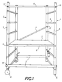
- la figure 1 est une vue en perspective d'un échafaudage selon l'invention,
- la figure 2 est une vue en perspective d'une échelle développée, obtenue après transformation dudit échafaudage,
- la figure 3 est une vue en élévation d'une extrémité du plateau horizontal,
- la figure 4 est une vue en coupe transversale dudit plateau horizontal encastré entre les deux échelles verticales,
- la figure 5 est une vue en coupe suivant la ligne V-V d'une partie de la figure 4, et
- la figure 6 est une vue de face d'une version d'échelle pourvue à sa base d'un arceau de stabilisation.
- En référence aux figures, l'échafaudage comporte deux échelles 1 et 2 verticales, chacune composée de deux montants 5 reliés entre eux par des échelons 8 tubulaires antidérapants.
- Ces échelles sont reliées au moyen d'un plateau 3 horizontal autobloquant, rigidifié par deux longerons de renfort 9 équipés à chacune de leurs extrémités d'un embout souple 10. Ces embouts souples 10, obturant les longerons de renfort 9, servent de butées de maintien longitudinal du plateau 3 horizontal encastré entre les montants 5 et un échelon 8 de chaque échelle verticale 1 et 2. Lesdits embouts souples 10 peuvent être interchangeables et sont réalisés dans une matière synthétique déformable, assurant ainsi une contrainte sur les deux échelons 8 supportant le plateau 3 horizontal. Les deux longerons de renfort 9 présentent des longueurs légèrement différentes, le longeron le plus long étant placé du côté ouvert de l'échafaudage pour augmenter la contrainte entre les deux échelles. Cette tension rigidifie l'ensemble de l'échafaudage et évite tout déplacement intempestif du plateau 3 horizontal autobloquant.
- L'écartement des deux échelles verticales 1 et 2 est assuré à leur base par deux longerons de base 4, articulés à chacune de leurs extrémités aux montants 5 correspondants de chaque échelle 1, 2 au moyen d'axes filetés 13 solidaires des longerons de base 4 et noyées dans des alvéoles 12 correspondantes prévues dans les montants 5. Lesdits longerons de base 4 sont munis de crans antidérapants et peuvent être utilisés comme échelons pour accéder au plateau 3.
- Un bras de croisillon 7 reliant les deux échelles 1 et 2 assure la rigidité longitudinale de l'échafaudage. Ce bras de croisillon 7 est articulé à chacune de ses extrémités à un des montants 5 correspondant de chaque échelle 1, 2 au moyen d'un axe fileté 13 solidaire du bras de croisillon 7 traversant une alvéole 12 prévue dans le montant 5 correspondant et maintenue par un écrou à dévissage rapide 13′ comme par exemple un écrou à oreilles.
- Une lisse de sécurité 6 est prévue dans la partie supérieure et est également articulée à chacune de ses extrémités à un des montants 5 correspondant de chaque échelle 1, 2 de la même manière que le bras de croisillon 7. Comme son nom l'indique, cette lisse 6 est destinée au maintien et à la sécurité de l'utilisateur.
- Une des deux échelles verticales est équipée de roulettes 11 permettant un déplacement de l'échafaudage, par l'utilisateur, en le maintenant d'une seule main.
- Tous les éléments tubulaires sont équipés d'embouts 15 en matière synthétique et sont interchangeables.
- Dans une autre version de réalisation, une ou les deux échelles 1, 2 verticales peuvent être élargies à leur base, en prévoyant un arceau de stabilisation 18 en lieu et place du premier échelon 8, pourvu de deux supports d'appui dont l'écartement est supérieur à l'écartement des deux montants de chaque échelle, assurant à l'ensemble une très grande stabilité latérale. Cet arceau 18 est muni de crans antidérapants permettant à l'utilisateur de poser son pied en toute sécurité et d'embouts 19 en matière synthétique. Ledit arceau peut être muni de roulettes pivotantes et autoblocables (non représentées).
- Cet échafaudage peut être transformé en échelle développée d'appui, en enlevant le plateau 3 horizontal par simple pression manuelle du bas vers le haut, et le bras de croisillon 7 en dévissant manuellement les deux écrous 13' à serrage rapide. Il suffit de rapprocher les deux échelles verticales 1 et 2. Les deux longerons de base 4 articulés guident l'ensemble et lorsque les deux échelles 1 et 2 sont l'une contre l'autre, une ou deux brides 16 fixées sur un des échelons 8 d'une échelle 1 reçoit un échelon de l'échelle 2. Le blocage est réalisé à l'aide d'une vis 17 agencée pour rapprocher les deux flasques d'une bride 16. Les deux échelles 1 et 2 sont ainsi verrouillées en position développée, les roulettes 11 étant appuyées contre la façade.
- Cet échafaudage peut être plié de manière à occuper un encombrement réduit pour son stockage ou son rangement, en enlevant le plateau 3 horizontal, l'axe de maintien 13 d'une extrémité du bras de croisillon 7 et l'axe de maintien 13 d'une extrémité de la lisse de sécurité 6. L'échelle 2 munie des roulettes 11 est rabattue sur les longerons de base 4 tandis que l'échelle 1 est rabattue sous lesdits longerons 4. Le plateau 3 est ensuite posé sur l'ensemble plié et le tout peut être rangé ou stocké en ne prenant qu'un minimum de place.
- Toutes les pièces principales composant l'échafaudage objet de la présente invention ne présentent pas une densité supérieure à 2,7 (densité de l'aluminium). Les longerons de renfort 9 servant de raidisseurs au plateau 3 horizontal ont l'avantage de le rigidifier tout en allégeant sa masse totale. Ce gain de poids réalisé, permet un allègement de l'échafaudage d'environ 30 % par rapport aux échafaudages disponibles sur le marché. Cet avantage facilite aussi la manutention et l'utilisation de ce produit.
- La présente invention n'est pas limitée à l'exemple de réalisation décrit ci-dessus, mais elle s'étend à toute modification variante évidente pour un homme de métier.
Claims (10)
- Echafaudage comprenant deux échelles verticales maintenues parallèlement entre elles par un plateau horizontal, deux longerons de base, au moins un bras de croisillon et des moyens de blocage des échelles en position verticale, le plateau horizontal (3) étant rigidifié par deux longerons de renfort, caractérisé en ce que les moyens de blocage comportent lesdits longerons de renfort (9) pourvus à leurs extrémités d'embouts souples agencés pour prendre respectivement appui contre un échelon de chacune des deux échelles.
- Echafaudage selon la revendication 1, caractérisé en ce que les embouts souples sont en matière synthétique déformable.
- Echafaudage selon la revendication 1, caractérisé en ce que les deux longerons de renfort (9) présentent des longueurs légèrement différentes.
- Echafaudage selon la revendication 1, caractérisé en ce que la largeur du plateau (3) est égale à l'espacement des montants (5) de chaque échelle.
- Echafaudage selon la revendication 1, caractérisé en ce que les deux longerons de base (4) sont situés à la base de l'échafaudage pour définir l'écartement des deux échelles (1) et (2) et en ce qu'ils sont articulés à chacune de leurs extrémités sur les montants (5) correspondants.
- Echafaudage selon la revendication 5, caractérisé en ce que les deux longerons de base (4) sont des profilés qui constituent des échelons d'accès au plateau (3).
- Echafaudage selon la revendication 1, caractérisé en ce qu'il comporte une lisse de sécurité (6) articulée à chacune de ses extrémités sur un des montants (5) de chacune des deux échelles (1) et (2).
- Echafaudage selon la revendication 1, caractérisé en ce que les deux échelles (1) et (2) verticales et en ce que les deux longerons de base (4) et la lisse de sécurité (6) articulés sur les montants (5) desdites échelles forment un parallélogramme déformable agencé pour permettre un pliage de l'échafaudage et sa transformation en échelle développée.
- Echafaudage selon la revendication 1, caractérisé en ce que les échelles (1) et (2) comportent à la place du premier échelon, un arceau de stabilisation (18) pourvu de deux supports d'appui dont l'écartement est supérieur à l'écartement des deux montants (5) de chaque échelle.
- Echafaudage selon la revendication 9, caractérisé en ce que l'arceau de stabilisation (18) est muni de roulettes pivotantes et autoblocables.
Applications Claiming Priority (2)
| Application Number | Priority Date | Filing Date | Title |
|---|---|---|---|
| FR9107198A FR2677391A1 (fr) | 1991-06-10 | 1991-06-10 | Echafaudage pliant transformable en echelle. |
| FR9107198 | 1991-06-10 |
Publications (1)
| Publication Number | Publication Date |
|---|---|
| EP0518794A1 true EP0518794A1 (fr) | 1992-12-16 |
Family
ID=9413780
Family Applications (1)
| Application Number | Title | Priority Date | Filing Date |
|---|---|---|---|
| EP92440074A Withdrawn EP0518794A1 (fr) | 1991-06-10 | 1992-06-09 | Echafaudage pliant transformable en échelle |
Country Status (2)
| Country | Link |
|---|---|
| EP (1) | EP0518794A1 (fr) |
| FR (1) | FR2677391A1 (fr) |
Families Citing this family (1)
| Publication number | Priority date | Publication date | Assignee | Title |
|---|---|---|---|---|
| CN110454077A (zh) * | 2019-09-11 | 2019-11-15 | 李鹏飞 | 一种多功能梯子 |
Citations (5)
| Publication number | Priority date | Publication date | Assignee | Title |
|---|---|---|---|---|
| GB894259A (en) * | 1960-03-09 | 1962-04-18 | Thomas Ltd Martin | Improvements in or relating to builders' staging |
| FR2313546A2 (fr) * | 1975-06-06 | 1976-12-31 | Saint Martin Charles | Echelle double utilisable comme echafaudage |
| WO1986001847A1 (fr) * | 1984-09-20 | 1986-03-27 | John Clement Preston | Module d'echafaudage et son procede de montage |
| EP0276489A1 (fr) * | 1987-01-25 | 1988-08-03 | Langer geb. Layher, Ruth | Plateforme d'échafaudage |
| EP0348885A2 (fr) * | 1988-07-01 | 1990-01-03 | Langer, Ruth, geb. Layher | Elément d'échafaudage non-vertical avec un dispositif de fixation |
-
1991
- 1991-06-10 FR FR9107198A patent/FR2677391A1/fr not_active Withdrawn
-
1992
- 1992-06-09 EP EP92440074A patent/EP0518794A1/fr not_active Withdrawn
Patent Citations (5)
| Publication number | Priority date | Publication date | Assignee | Title |
|---|---|---|---|---|
| GB894259A (en) * | 1960-03-09 | 1962-04-18 | Thomas Ltd Martin | Improvements in or relating to builders' staging |
| FR2313546A2 (fr) * | 1975-06-06 | 1976-12-31 | Saint Martin Charles | Echelle double utilisable comme echafaudage |
| WO1986001847A1 (fr) * | 1984-09-20 | 1986-03-27 | John Clement Preston | Module d'echafaudage et son procede de montage |
| EP0276489A1 (fr) * | 1987-01-25 | 1988-08-03 | Langer geb. Layher, Ruth | Plateforme d'échafaudage |
| EP0348885A2 (fr) * | 1988-07-01 | 1990-01-03 | Langer, Ruth, geb. Layher | Elément d'échafaudage non-vertical avec un dispositif de fixation |
Also Published As
| Publication number | Publication date |
|---|---|
| FR2677391A1 (fr) | 1992-12-11 |
Similar Documents
| Publication | Publication Date | Title |
|---|---|---|
| EP0296916A1 (fr) | Elément modulaire de construction, notamment d'échelle ou d'échafaudage | |
| EP0900037A1 (fr) | Siege compose d'elements assemblables | |
| FR2929304A1 (fr) | Dispositif d'echafaudage repliable et a hauteur de travail modulable | |
| EP0468907A1 (fr) | Passerelle-support repliable pour banches de coffrage | |
| EP1783322B1 (fr) | Echelle à plate-forme et tubes garde-corps repliables, notamment pour les échelles coulissantes | |
| EP3940189B1 (fr) | Dispositif de travail en hauteur a garde-corps articule et portillon automatique | |
| EP0518794A1 (fr) | Echafaudage pliant transformable en échelle | |
| EP1109987A1 (fr) | Structure support portative utilisable en tant qu'echelle ou escabeau | |
| EP0674741A1 (fr) | Echafaudage reglable destine a prendre appui sur une surface en pente | |
| FR2745030A1 (fr) | Nacelle de travail destinee a etre utilisee sur une echelle | |
| FR3113695A1 (fr) | Dispositif de travail en hauteur a garde-corps articule et moyen de maintien en position repliee | |
| FR2908804A1 (fr) | Garde-corps d'echafaudage a montage en securite | |
| FR3159599A1 (fr) | Bacs à linge superposés | |
| EP0580456B1 (fr) | Echafaudage | |
| FR2616468A1 (fr) | Element modulaire de construction, notamment d'echelle ou d'echafaudage | |
| FR2510164A1 (fr) | Passerelle a consoles pliables pour travaux de batiments | |
| EP0874108A1 (fr) | Dispositif pour le montage en sécurité des échafaudages | |
| FR2523829A1 (fr) | Ensemble transformable pouvant etre utilise a volonte comme table, etabli ou echafaudage | |
| FR2627533A1 (fr) | Echafaudage pliable comportant un plateau equipe de pieds articules et d'un garde-corps | |
| FR2716491A1 (fr) | Echelle, notamment pour travaux domestiques. | |
| FR3159817A1 (fr) | Moyen de maintien en position de rangement d’un profilé de stabilisateur d’un dispositif de travail en hauteur | |
| FR3101088A1 (fr) | Echafaudage | |
| FR2577202A1 (fr) | Casier pour le conditionnement d'un lot d'objets, notamment d'objets lourds et volumineux tels que des bouteilles de gaz liquefie | |
| FR2927919A1 (fr) | Element d'echafaudage et ensemble d'echafaudage comprenant un tel element | |
| EP2071099A1 (fr) | Procédé de montage et démontage en securité d'un échafaudage roulant et lisses de montage de securité utilisées |
Legal Events
| Date | Code | Title | Description |
|---|---|---|---|
| PUAI | Public reference made under article 153(3) epc to a published international application that has entered the european phase |
Free format text: ORIGINAL CODE: 0009012 |
|
| AK | Designated contracting states |
Kind code of ref document: A1 Designated state(s): AT BE CH DE DK ES FR GB GR IT LI LU MC NL PT SE |
|
| 18D | Application deemed to be withdrawn |
Effective date: 19930617 |