EP0519228A1 - Capsule à haute tension avec au minimum deux couches - Google Patents
Capsule à haute tension avec au minimum deux couches Download PDFInfo
- Publication number
- EP0519228A1 EP0519228A1 EP92108649A EP92108649A EP0519228A1 EP 0519228 A1 EP0519228 A1 EP 0519228A1 EP 92108649 A EP92108649 A EP 92108649A EP 92108649 A EP92108649 A EP 92108649A EP 0519228 A1 EP0519228 A1 EP 0519228A1
- Authority
- EP
- European Patent Office
- Prior art keywords
- protective covering
- voltage system
- voltage
- encapsulation
- protective
- Prior art date
- Legal status (The legal status is an assumption and is not a legal conclusion. Google has not performed a legal analysis and makes no representation as to the accuracy of the status listed.)
- Granted
Links
- 239000002245 particle Substances 0.000 claims abstract description 37
- 238000005538 encapsulation Methods 0.000 claims abstract description 21
- 238000009434 installation Methods 0.000 claims abstract 3
- 230000001681 protective effect Effects 0.000 claims description 76
- 239000000463 material Substances 0.000 claims description 6
- 239000011253 protective coating Substances 0.000 claims description 5
- 239000004698 Polyethylene Substances 0.000 claims description 4
- GWEVSGVZZGPLCZ-UHFFFAOYSA-N Titan oxide Chemical compound O=[Ti]=O GWEVSGVZZGPLCZ-UHFFFAOYSA-N 0.000 claims description 4
- -1 polyethylene Polymers 0.000 claims description 4
- 229920000573 polyethylene Polymers 0.000 claims description 4
- 239000000126 substance Substances 0.000 claims description 3
- 239000004593 Epoxy Substances 0.000 claims description 2
- PNEYBMLMFCGWSK-UHFFFAOYSA-N aluminium oxide Inorganic materials [O-2].[O-2].[O-2].[Al+3].[Al+3] PNEYBMLMFCGWSK-UHFFFAOYSA-N 0.000 claims description 2
- 229910052593 corundum Inorganic materials 0.000 claims description 2
- 239000000203 mixture Substances 0.000 claims description 2
- 239000003973 paint Substances 0.000 claims description 2
- 229910001845 yogo sapphire Inorganic materials 0.000 claims description 2
- 239000004922 lacquer Substances 0.000 claims 1
- 239000011241 protective layer Substances 0.000 abstract description 6
- 239000002184 metal Substances 0.000 abstract 1
- 238000009413 insulation Methods 0.000 description 6
- 230000000694 effects Effects 0.000 description 5
- 238000009825 accumulation Methods 0.000 description 4
- 230000008878 coupling Effects 0.000 description 3
- 238000010168 coupling process Methods 0.000 description 3
- 238000005859 coupling reaction Methods 0.000 description 3
- 239000010410 layer Substances 0.000 description 3
- 230000000717 retained effect Effects 0.000 description 3
- 230000015556 catabolic process Effects 0.000 description 2
- 238000011161 development Methods 0.000 description 2
- 230000018109 developmental process Effects 0.000 description 2
- 238000005299 abrasion Methods 0.000 description 1
- 239000002313 adhesive film Substances 0.000 description 1
- XAGFODPZIPBFFR-UHFFFAOYSA-N aluminium Chemical compound [Al] XAGFODPZIPBFFR-UHFFFAOYSA-N 0.000 description 1
- 229910052782 aluminium Inorganic materials 0.000 description 1
- 230000003321 amplification Effects 0.000 description 1
- 238000004140 cleaning Methods 0.000 description 1
- 239000011248 coating agent Substances 0.000 description 1
- 238000000576 coating method Methods 0.000 description 1
- 238000004040 coloring Methods 0.000 description 1
- 230000001419 dependent effect Effects 0.000 description 1
- 239000000835 fiber Substances 0.000 description 1
- 238000003199 nucleic acid amplification method Methods 0.000 description 1
- 239000007787 solid Substances 0.000 description 1
- 230000003746 surface roughness Effects 0.000 description 1
Images

Classifications
-
- H—ELECTRICITY
- H02—GENERATION; CONVERSION OR DISTRIBUTION OF ELECTRIC POWER
- H02G—INSTALLATION OF ELECTRIC CABLES OR LINES, OR OF COMBINED OPTICAL AND ELECTRIC CABLES OR LINES
- H02G5/00—Installations of bus-bars
- H02G5/06—Totally-enclosed installations, e.g. in metal casings
- H02G5/063—Totally-enclosed installations, e.g. in metal casings filled with oil or gas
- H02G5/065—Particle traps
Definitions
- the invention is based on a high-voltage system according to the preamble of claim 1.
- High-voltage systems which have a grounded metallic encapsulation filled with insulating gas, the inner surface of which, opposite the high-voltage active parts, is provided with a protective coating.
- This protective coating is intended to make this surface smooth so that it can be cleaned without fibers or other residues from cleaning aids being retained by surface roughness of the inner surface, which would reduce the dielectric strength of the gas insulation section.
- the surface of the active parts is often provided with a similar protective covering in such systems.
- conductive particles can arise as a result of abrasion at moving contact points or from switching residues. As a rule, these particles can move freely within the encapsulation and can accumulate at certain points in such a way that the dielectric strength of the insulating gas sections is reduced.
- the invention seeks to remedy this.
- the invention as characterized in the claims, solves the problem of creating a high-voltage system in which a reduction in the dielectric strength of the insulating gas sections cannot occur due to unfavorably attached free particles.
- a metallic wall 1 has peaks 2 and other unevenness on the surface.
- a first protective covering 3 covers the surface of the wall 1 and levels out the unevenness, so that none of the tips 2 breaks through this protective covering.
- the protective covering 3 is covered by a second protective covering 4, the protective covering 4 either being applied directly to the protective covering 3 or being intimately connected to it, for example with the aid of electrostatic forces.
- Electrically conductive particles 5 are attached to the protective covering 4, only one of which is shown.
- the insulating gas-filled interior of the high-voltage system connects above the protective covering 4.
- the wall 1 can therefore either as part of an encapsulation of the high-voltage system or as part of its active parts. However, it is also possible to dispense with coating the active parts with the protective covering 4.
- the first protective covering 3 has a comparatively high electrical conductivity or a large dielectric constant ⁇ 1, which is advantageously in the range around 30. This is achieved in that particles 6 are introduced into the base material for the first protective covering 3, for example an epoxy paint.
- the particles 6 can for example consist of TiO2 components or conductive coated Al2O3 or a mixture of both substances. Other electrically conductive substances are also conceivable for this introduction. Due to the conductive protective covering 3, the surface of the coated part is approximated to a surface that acts as a dielectric smooth surface. The tips 2 are no longer dielectrically harmful, since they lie within the electrically conductive or dielectrically active protective covering 3.
- the second protective covering 4 has an electrically insulating effect, ie it has a comparatively small dielectric constant ⁇ 2 compared to the protective covering 3.
- Protective coverings 4 of this type can be produced on the basis of polyethylene. It is also possible to use foamed material based on polyethylene.
- the protective covering 4 can be designed as an electrostatically adhesive film 3 which can be removed if necessary.
- the second protective covering 4, like the first protective covering 3, can also be constructed in multiple layers if dielectric boundary conditions or the processability of the material for this protective covering 4 should make this necessary.
- the second protective covering 4 generally has a dielectric constant ⁇ 2 in the range from 1 to 2.
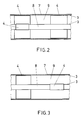
- FIG. 2 shows a section through a cylindrical high-voltage system with a metallic encapsulation 7, an active part 8 and an interior space 9 filled with insulating gas.
- the inner surface of the encapsulation 7 and the outer surface of the active part 8 are provided with the first protective covering 3. It is possible to coat the entire inner surface of the encapsulation 7 and also the entire surface of the active part 8 with the second protective layer 4. However, it is also sensible, as indicated in the left part of FIG. 2, to provide the protective layer 4 only in one area or in several areas of the high-voltage system, specifically on the active part 8 and opposite on the inside of the encapsulation 7. For some applications, it is sufficient however, as indicated in the right part of FIG. 2, only to provide the inner surface of the encapsulation 7 with the second protective layer 4, and this can be done in one or more areas of the high-voltage system. However, it is also possible to provide the entire inner surface of the encapsulation 7 with the protective covering 4.
- Fig. 3 shows a further possibility of applying protective coverings 4 in the high-voltage system.
- the protective coverings 4 are namely offset from one another.
- Such designs can be provided several times in the high-voltage system. It is also possible to combine the designs according to FIGS. 2 and 3 with one another in order to achieve an optimal distribution of the protective coverings 4 in accordance with the requirements of the respective high-voltage system.
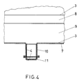
- Fig. 4 shows a high-voltage system with a connector 10 attached in the lower region of the encapsulation 7, which is closed gas-tight by a cover 11.
- the inner wall of the connector 10 and the inner wall of the cover 11 are provided with the second protective covering 4.
- This version is intended as a particle trap.
- the first protective covering 3 very advantageously reduces the local roughness-related maximum field strength in the interior 9 to acceptable values.
- the second protective covering 4 has the task of increasing the so-called lifting field, ie the field strength that is necessary to make the free, electrically conductive particles 5 lift off.
- the macroscopic lifting field E0 can be estimated from the capacitive coupling of the particle 5 to the respective base, here referred to as wall 1. The following relationship applies: E0 ⁇ ⁇ ⁇ C '(-0.3) E0 is the lifting field strength, ⁇ is the density of the particle 5, C 'is the area-related average capacitance of the protective coverings 3 and 4 connected in series with respect to the rough surface of the wall 1.
- the capacitive coupling of the particle 5 can be estimated according to the following relationship: E0 ⁇ 2.25 ⁇ 106 V ⁇ m 0.2 kg- 0.5 ⁇ ⁇ (d / ⁇ 2) 0.3 E0 is the field strength at which the particle 5 is not yet lifted off, ⁇ is the density of the particle 5, d is the thickness of the second protective coating 4, ⁇ 2 is the dielectric constant of the protective coating 4.
- This value of E0 is already in a range which is generally not exceeded in conventional high-voltage systems, so that these simple measures can advantageously increase the operational safety of this system.
- the material of the protective covering 4 must accordingly have the smallest possible dielectric constant ⁇ 2. In this way, the availability of the high-voltage system can be increased with simple means and low material expenditure.
- the particles 5 are held on the protective covering 4 and cannot move on in the system, so that no accumulation of particles can occur which could lead to insulation breakdowns.
- the protective covering 4 is now always provided in such places where the particles 5 can be retained without significantly reducing the insulation strength. A accumulation of conductive particles 5, which could lead to insulation breakdowns, is not possible in this system. Furthermore, an accumulation of conductive particles 5 on solid insulation can also be reliably avoided in this way.
- the protective coverings 4 are advantageously applied in those areas of the high-voltage system which are less stressed dielectric than the other areas of the system.
- the local amplification of the dielectric load as a result of the particles 5 which act as dielectrically act as tips does not have as great an effect in these regions which are otherwise less loaded with dielectric. Any danger to the system from these specifically retained particles 5 is thus avoided with great certainty.
- the second protective covering 4 is arranged on the inner surface of the encapsulation in a different area than the corresponding second protective covering 4 on the outer surface of the active part 8, since in this case the field disturbances are caused by the particles 5 deposited do not overlap in the same place and thus cannot impermissibly reduce the dielectric strength.
- the arrangement of the second protective covering 4 in the vicinity of assembly openings in the encapsulation 7 or in areas of the system that are accessible during revisions is expedient, since the protective covering 4 can thus be freed from the accumulated particles 5 easily and without additional assembly effort. It also seems to make sense to specifically color the second protective covering 4 in order to make the zones to be cleaned more visible. However, if the entire system is covered with a protective covering 4 coated, which is quite possible with certain system configurations, this special coloring is not necessary.
- Particle traps in high-voltage systems with protective coverings 4 in order to ensure that the particles 5 remain in these traps safely.
- Particle traps in existing systems can be upgraded with comparatively little effort using newly installed protective coverings 3 and 4 in order to achieve greater operational reliability of the high-voltage system.
- the second protective covering 4 is designed as a removable film which adheres electrostatically to the protective covering 3, this film can be removed together with the attached particles 5. Such a possibility would be particularly advantageous during commissioning if, for example, after a trial operation of the system, this film could be removed with the majority of all loose particles 5.
- the capacitive coupling between the film, the second layer of the protective covering 4 and the protective covering 3 can be designed in such a way that optimal protection against freely moving particles 5 is achieved.
Landscapes
- Chemical & Material Sciences (AREA)
- Oil, Petroleum & Natural Gas (AREA)
- Gas-Insulated Switchgears (AREA)
- Electrostatic Separation (AREA)
Applications Claiming Priority (2)
| Application Number | Priority Date | Filing Date | Title |
|---|---|---|---|
| DE4120309A DE4120309A1 (de) | 1991-06-20 | 1991-06-20 | Hochspannungsanlage |
| DE4120309 | 1991-06-20 |
Publications (2)
| Publication Number | Publication Date |
|---|---|
| EP0519228A1 true EP0519228A1 (fr) | 1992-12-23 |
| EP0519228B1 EP0519228B1 (fr) | 1995-11-22 |
Family
ID=6434328
Family Applications (1)
| Application Number | Title | Priority Date | Filing Date |
|---|---|---|---|
| EP92108649A Revoked EP0519228B1 (fr) | 1991-06-20 | 1992-05-22 | Capsule à haute tension avec au minimum deux couches |
Country Status (4)
| Country | Link |
|---|---|
| US (1) | US5264660A (fr) |
| EP (1) | EP0519228B1 (fr) |
| JP (1) | JPH05191908A (fr) |
| DE (2) | DE4120309A1 (fr) |
Cited By (5)
| Publication number | Priority date | Publication date | Assignee | Title |
|---|---|---|---|---|
| CN1041982C (zh) * | 1993-12-28 | 1999-02-03 | Abb研究有限公司 | 高压设备 |
| WO1999063634A1 (fr) * | 1998-06-02 | 1999-12-09 | Abb Research Ltd. | Fil a haute tension a revetement protecteur hydrophile |
| WO2007006685A1 (fr) * | 2005-07-07 | 2007-01-18 | Siemens Aktiengesellschaft | Procede pour entretenir un tuyau comportant un systeme de pieges a particules qui s'etend le long du tuyau, et dispositifs servant a la mise en oeuvre de ce procede |
| FR2971101A1 (fr) * | 2011-01-27 | 2012-08-03 | Edmond Thuries | Systeme de transport de l'energie electrique sous enveloppe metallique a isolation mixte solide et gazeuse, pouvant etre enterre |
| EP2405550A4 (fr) * | 2009-03-06 | 2017-04-12 | Kabushiki Kaisha Toshiba | Dispositif isolé hermétique |
Families Citing this family (6)
| Publication number | Priority date | Publication date | Assignee | Title |
|---|---|---|---|---|
| US5656796A (en) * | 1993-04-26 | 1997-08-12 | Fmc Corp. | High energy flexible coaxial cable and connections |
| DE4446944A1 (de) | 1994-12-28 | 1996-07-04 | Abb Research Ltd | Hochspannungsanlage |
| EP1569313B1 (fr) | 2004-02-27 | 2006-10-18 | ABB Technology AG | Appareil Haute Tension avec piège à particules |
| DE102004032018A1 (de) * | 2004-06-28 | 2006-01-12 | Siemens Ag | Kapselungsgehäuse einer Elektroenergieübertragungseinrichtung mit einer Teilchenfalle |
| JP5200282B2 (ja) * | 2008-10-03 | 2013-06-05 | 三菱電機株式会社 | 絶縁スペーサ |
| EP3067149A1 (fr) | 2015-03-13 | 2016-09-14 | Wartmann Technologie AG | Tube pressurisé pour commutateurs isolés ou conducteurs et procédé de production |
Citations (4)
| Publication number | Priority date | Publication date | Assignee | Title |
|---|---|---|---|---|
| CH570720A5 (fr) * | 1974-04-17 | 1975-12-15 | Bbc Brown Boveri & Cie | |
| DE3112022A1 (de) * | 1981-03-26 | 1982-10-14 | Siemens AG, 1000 Berlin und 8000 München | "elektrische anlage oder geraet" |
| US4564721A (en) * | 1984-04-18 | 1986-01-14 | Hitachi, Ltd. | Gas-insulated electrical apparatus with electret for captivating conductive particles and method of removing such particles during assembly thereof |
| US4667061A (en) * | 1985-04-02 | 1987-05-19 | Hitachi, Ltd. | Gas insulated apparatus with internal coated insulation layer of high dielectric constant |
Family Cites Families (11)
| Publication number | Priority date | Publication date | Assignee | Title |
|---|---|---|---|---|
| GB1068970A (en) * | 1964-11-19 | 1967-05-17 | Central Electr Generat Board | Improvements in or relating to electric cables with compressed gas insulation |
| US3433891A (en) * | 1966-12-29 | 1969-03-18 | Gen Electric | Graded insulated cable |
| US3515909A (en) * | 1968-08-14 | 1970-06-02 | John George Trump | Dielectric-covered electrodes |
| US3564108A (en) * | 1969-08-14 | 1971-02-16 | Rca Corp | Coaxial transmission line |
| DE2323379A1 (de) * | 1973-05-09 | 1974-11-21 | Siemens Ag | Laengswasserdichtes koaxiales hochfrequenzkabel |
| US3985948A (en) * | 1973-11-28 | 1976-10-12 | General Cable Corporation | Watertight disc coaxial cables |
| US3856978A (en) * | 1974-02-21 | 1974-12-24 | Westinghouse Electric Corp | Adherent coating for captivating small particles in gas-insulated electrical equipment |
| US4029890A (en) * | 1976-04-19 | 1977-06-14 | General Electric Company | Particle trapping elbow joint for enclosed high voltage electric bus apparatus |
| DE2838358A1 (de) * | 1978-09-02 | 1980-03-20 | Licentia Gmbh | Verfahren zur vergroesserung der spannungsfestigkeit von isolatoren |
| DE3543301A1 (de) * | 1985-12-07 | 1987-06-11 | Roehm Gmbh | Elektrisch leitende feste kunststoffe |
| IT1227546B (it) * | 1988-12-09 | 1991-04-15 | Muller Sergio | Cavo coassiale perfezionato e relativo metodo di fabbricazione |
-
1991
- 1991-06-20 DE DE4120309A patent/DE4120309A1/de not_active Withdrawn
-
1992
- 1992-05-22 DE DE59204400T patent/DE59204400D1/de not_active Revoked
- 1992-05-22 EP EP92108649A patent/EP0519228B1/fr not_active Revoked
- 1992-05-29 US US07/890,248 patent/US5264660A/en not_active Expired - Fee Related
- 1992-06-17 JP JP4158185A patent/JPH05191908A/ja active Pending
Patent Citations (4)
| Publication number | Priority date | Publication date | Assignee | Title |
|---|---|---|---|---|
| CH570720A5 (fr) * | 1974-04-17 | 1975-12-15 | Bbc Brown Boveri & Cie | |
| DE3112022A1 (de) * | 1981-03-26 | 1982-10-14 | Siemens AG, 1000 Berlin und 8000 München | "elektrische anlage oder geraet" |
| US4564721A (en) * | 1984-04-18 | 1986-01-14 | Hitachi, Ltd. | Gas-insulated electrical apparatus with electret for captivating conductive particles and method of removing such particles during assembly thereof |
| US4667061A (en) * | 1985-04-02 | 1987-05-19 | Hitachi, Ltd. | Gas insulated apparatus with internal coated insulation layer of high dielectric constant |
Cited By (6)
| Publication number | Priority date | Publication date | Assignee | Title |
|---|---|---|---|---|
| CN1041982C (zh) * | 1993-12-28 | 1999-02-03 | Abb研究有限公司 | 高压设备 |
| WO1999063634A1 (fr) * | 1998-06-02 | 1999-12-09 | Abb Research Ltd. | Fil a haute tension a revetement protecteur hydrophile |
| WO2007006685A1 (fr) * | 2005-07-07 | 2007-01-18 | Siemens Aktiengesellschaft | Procede pour entretenir un tuyau comportant un systeme de pieges a particules qui s'etend le long du tuyau, et dispositifs servant a la mise en oeuvre de ce procede |
| CN100561033C (zh) * | 2005-07-07 | 2009-11-18 | 西门子公司 | 维护具有沿管件延伸的粒子井系统的管件的方法及实施该方法的装置 |
| EP2405550A4 (fr) * | 2009-03-06 | 2017-04-12 | Kabushiki Kaisha Toshiba | Dispositif isolé hermétique |
| FR2971101A1 (fr) * | 2011-01-27 | 2012-08-03 | Edmond Thuries | Systeme de transport de l'energie electrique sous enveloppe metallique a isolation mixte solide et gazeuse, pouvant etre enterre |
Also Published As
| Publication number | Publication date |
|---|---|
| JPH05191908A (ja) | 1993-07-30 |
| US5264660A (en) | 1993-11-23 |
| DE59204400D1 (de) | 1996-01-04 |
| DE4120309A1 (de) | 1992-12-24 |
| EP0519228B1 (fr) | 1995-11-22 |
Similar Documents
| Publication | Publication Date | Title |
|---|---|---|
| DE2844725C2 (de) | Elektrode für einen Ozon-Generator | |
| EP0519228B1 (fr) | Capsule à haute tension avec au minimum deux couches | |
| DE69309400T2 (de) | Funkensicherer rotierender Zerstäuber | |
| DE1782048B2 (de) | Hochspannungseinrichtung in Form eines Hochspannungsgenerators oder Hochspannungs-Koaxialkabels | |
| DE102012204052B4 (de) | Hochspannungsdurchführung mit leitenden Einlagen für Gleichspannung und Verfahren zu ihrer Herstellung | |
| EP0214480B1 (fr) | Câble optique autoportant sans métal pour des lignes aériennes | |
| DE1615039B2 (de) | Isolieranordnung für Hochspannung | |
| EP0068067A1 (fr) | Résistance à haute tension pour isolateurs de lignes aériennes | |
| DE1441679A1 (de) | Breitbandfilter | |
| DE3013891C2 (de) | Elektrostatisches Pulverspritzverfahren zur Erzeugung eines Farbauftrags | |
| DE2050727C3 (de) | Überspannungsableiteranordnung | |
| DE4444554C2 (de) | Gekapselte elektrische Hochspannungsleitung | |
| DE69206381T2 (de) | Gerät zur Oberflächenbehandlung mittels Coronaentladung. | |
| DE2843120A1 (de) | Gekapselte blitzschutzvorrichtung | |
| DE69736916T2 (de) | Garnitur für Kabelendverschluss und Material für die Bildung der Garnitur | |
| CH645483A5 (de) | Vorrichtung zur ueberspannungsableitung. | |
| DE578225C (de) | Entionisierungseinrichtung zum Loeschen von Wechselstromlichtboegen | |
| DE2115636A1 (de) | Anordnung zur Kompensation von Stör kapazitäten an Halbleiterventilen | |
| DE1590536A1 (de) | Isolator | |
| DE2348136C3 (de) | Elektrisches Gerät für Hochspannung mit einer ein Isoliergas enthaltenden Kapselung aus Metall | |
| EP3909801B1 (fr) | Véhicule ferroviaire et procédé de fabrication d'un véhicule ferroviaire | |
| DE3715715A1 (de) | Abgeschirmtes gehaeuse | |
| DE762230C (de) | Elektrostatische Abschirmung fuer mit Wanderwellen beanspruchte, aus Scheibenspulen aufgebaute Roehrenwicklungen von elektrischen Transformatoren oder Drosselspulen | |
| EP0661788A1 (fr) | Arrangement à haute tension | |
| DE69808461T2 (de) | Von einer mit schirmen versehenen isolierhülse überdeckter kabelendverschluss |
Legal Events
| Date | Code | Title | Description |
|---|---|---|---|
| PUAI | Public reference made under article 153(3) epc to a published international application that has entered the european phase |
Free format text: ORIGINAL CODE: 0009012 |
|
| AK | Designated contracting states |
Kind code of ref document: A1 Designated state(s): CH DE FR GB IT LI |
|
| 17P | Request for examination filed |
Effective date: 19930604 |
|
| 17Q | First examination report despatched |
Effective date: 19940725 |
|
| GRAA | (expected) grant |
Free format text: ORIGINAL CODE: 0009210 |
|
| AK | Designated contracting states |
Kind code of ref document: B1 Designated state(s): CH DE FR GB IT LI |
|
| REF | Corresponds to: |
Ref document number: 59204400 Country of ref document: DE Date of ref document: 19960104 |
|
| ITF | It: translation for a ep patent filed | ||
| ET | Fr: translation filed | ||
| GBT | Gb: translation of ep patent filed (gb section 77(6)(a)/1977) |
Effective date: 19960126 |
|
| PLBI | Opposition filed |
Free format text: ORIGINAL CODE: 0009260 |
|
| PLBF | Reply of patent proprietor to notice(s) of opposition |
Free format text: ORIGINAL CODE: EPIDOS OBSO |
|
| 26 | Opposition filed |
Opponent name: SIEMENS AG Effective date: 19960822 |
|
| PLBF | Reply of patent proprietor to notice(s) of opposition |
Free format text: ORIGINAL CODE: EPIDOS OBSO |
|
| PGFP | Annual fee paid to national office [announced via postgrant information from national office to epo] |
Ref country code: GB Payment date: 19970410 Year of fee payment: 6 |
|
| PLAW | Interlocutory decision in opposition |
Free format text: ORIGINAL CODE: EPIDOS IDOP |
|
| APAC | Appeal dossier modified |
Free format text: ORIGINAL CODE: EPIDOS NOAPO |
|
| APAE | Appeal reference modified |
Free format text: ORIGINAL CODE: EPIDOS REFNO |
|
| APAC | Appeal dossier modified |
Free format text: ORIGINAL CODE: EPIDOS NOAPO |
|
| PG25 | Lapsed in a contracting state [announced via postgrant information from national office to epo] |
Ref country code: GB Free format text: LAPSE BECAUSE OF NON-PAYMENT OF DUE FEES Effective date: 19980522 |
|
| GBPC | Gb: european patent ceased through non-payment of renewal fee |
Effective date: 19980522 |
|
| PGFP | Annual fee paid to national office [announced via postgrant information from national office to epo] |
Ref country code: FR Payment date: 19990419 Year of fee payment: 8 |
|
| PGFP | Annual fee paid to national office [announced via postgrant information from national office to epo] |
Ref country code: DE Payment date: 19990420 Year of fee payment: 8 |
|
| PGFP | Annual fee paid to national office [announced via postgrant information from national office to epo] |
Ref country code: CH Payment date: 19990421 Year of fee payment: 8 |
|
| APAC | Appeal dossier modified |
Free format text: ORIGINAL CODE: EPIDOS NOAPO |
|
| RAP2 | Party data changed (patent owner data changed or rights of a patent transferred) |
Owner name: ABB BUSINESS SERVICES LTD. |
|
| RDAH | Patent revoked |
Free format text: ORIGINAL CODE: EPIDOS REVO |
|
| RDAG | Patent revoked |
Free format text: ORIGINAL CODE: 0009271 |
|
| STAA | Information on the status of an ep patent application or granted ep patent |
Free format text: STATUS: PATENT REVOKED |
|
| 27W | Patent revoked |
Effective date: 20000211 |
|
| REG | Reference to a national code |
Ref country code: CH Ref legal event code: PL |
|
| APAH | Appeal reference modified |
Free format text: ORIGINAL CODE: EPIDOSCREFNO |