EP0519622A2 - Boîte pour le palpeur d'ondes amorties et appareil - Google Patents
Boîte pour le palpeur d'ondes amorties et appareil Download PDFInfo
- Publication number
- EP0519622A2 EP0519622A2 EP92305121A EP92305121A EP0519622A2 EP 0519622 A2 EP0519622 A2 EP 0519622A2 EP 92305121 A EP92305121 A EP 92305121A EP 92305121 A EP92305121 A EP 92305121A EP 0519622 A2 EP0519622 A2 EP 0519622A2
- Authority
- EP
- European Patent Office
- Prior art keywords
- radiation
- sensor
- shell
- base
- port
- Prior art date
- Legal status (The legal status is an assumption and is not a legal conclusion. Google has not performed a legal analysis and makes no representation as to the accuracy of the status listed.)
- Withdrawn
Links
Images


Classifications
-
- G—PHYSICS
- G01—MEASURING; TESTING
- G01N—INVESTIGATING OR ANALYSING MATERIALS BY DETERMINING THEIR CHEMICAL OR PHYSICAL PROPERTIES
- G01N21/00—Investigating or analysing materials by the use of optical means, i.e. using sub-millimetre waves, infrared, visible or ultraviolet light
- G01N21/62—Systems in which the material investigated is excited whereby it emits light or causes a change in wavelength of the incident light
- G01N21/63—Systems in which the material investigated is excited whereby it emits light or causes a change in wavelength of the incident light optically excited
- G01N21/64—Fluorescence; Phosphorescence
- G01N21/645—Specially adapted constructive features of fluorimeters
- G01N21/648—Specially adapted constructive features of fluorimeters using evanescent coupling or surface plasmon coupling for the excitation of fluorescence
-
- G—PHYSICS
- G01—MEASURING; TESTING
- G01N—INVESTIGATING OR ANALYSING MATERIALS BY DETERMINING THEIR CHEMICAL OR PHYSICAL PROPERTIES
- G01N21/00—Investigating or analysing materials by the use of optical means, i.e. using sub-millimetre waves, infrared, visible or ultraviolet light
- G01N21/17—Systems in which incident light is modified in accordance with the properties of the material investigated
- G01N21/55—Specular reflectivity
- G01N21/552—Attenuated total reflection
-
- G—PHYSICS
- G01—MEASURING; TESTING
- G01N—INVESTIGATING OR ANALYSING MATERIALS BY DETERMINING THEIR CHEMICAL OR PHYSICAL PROPERTIES
- G01N21/00—Investigating or analysing materials by the use of optical means, i.e. using sub-millimetre waves, infrared, visible or ultraviolet light
- G01N21/75—Systems in which material is subjected to a chemical reaction, the progress or the result of the reaction being investigated
- G01N21/77—Systems in which material is subjected to a chemical reaction, the progress or the result of the reaction being investigated by observing the effect on a chemical indicator
- G01N21/7703—Systems in which material is subjected to a chemical reaction, the progress or the result of the reaction being investigated by observing the effect on a chemical indicator using reagent-clad optical fibres or optical waveguides
-
- Y—GENERAL TAGGING OF NEW TECHNOLOGICAL DEVELOPMENTS; GENERAL TAGGING OF CROSS-SECTIONAL TECHNOLOGIES SPANNING OVER SEVERAL SECTIONS OF THE IPC; TECHNICAL SUBJECTS COVERED BY FORMER USPC CROSS-REFERENCE ART COLLECTIONS [XRACs] AND DIGESTS
- Y10—TECHNICAL SUBJECTS COVERED BY FORMER USPC
- Y10S—TECHNICAL SUBJECTS COVERED BY FORMER USPC CROSS-REFERENCE ART COLLECTIONS [XRACs] AND DIGESTS
- Y10S435/00—Chemistry: molecular biology and microbiology
- Y10S435/808—Optical sensing apparatus
-
- Y—GENERAL TAGGING OF NEW TECHNOLOGICAL DEVELOPMENTS; GENERAL TAGGING OF CROSS-SECTIONAL TECHNOLOGIES SPANNING OVER SEVERAL SECTIONS OF THE IPC; TECHNICAL SUBJECTS COVERED BY FORMER USPC CROSS-REFERENCE ART COLLECTIONS [XRACs] AND DIGESTS
- Y10—TECHNICAL SUBJECTS COVERED BY FORMER USPC
- Y10S—TECHNICAL SUBJECTS COVERED BY FORMER USPC CROSS-REFERENCE ART COLLECTIONS [XRACs] AND DIGESTS
- Y10S436/00—Chemistry: analytical and immunological testing
- Y10S436/805—Optical property
-
- Y—GENERAL TAGGING OF NEW TECHNOLOGICAL DEVELOPMENTS; GENERAL TAGGING OF CROSS-SECTIONAL TECHNOLOGIES SPANNING OVER SEVERAL SECTIONS OF THE IPC; TECHNICAL SUBJECTS COVERED BY FORMER USPC CROSS-REFERENCE ART COLLECTIONS [XRACs] AND DIGESTS
- Y10—TECHNICAL SUBJECTS COVERED BY FORMER USPC
- Y10S—TECHNICAL SUBJECTS COVERED BY FORMER USPC CROSS-REFERENCE ART COLLECTIONS [XRACs] AND DIGESTS
- Y10S436/00—Chemistry: analytical and immunological testing
- Y10S436/807—Apparatus included in process claim, e.g. physical support structures
Definitions
- This invention relates to improved evanescent wave sensors for use in spectrophotometric assays of analytes in fluids, and more particularly to such sensors having a shell with inner and outer wall surfaces which propagate radiation between them by total internal reflection.
- the evanescent wave is an electromagnetic waveform which typically extends less than a wavelength into the surrounding medium. However, this penetration is sufficient to permit substantial optical interaction between the evanescent wave component and target substance(s) or analytes in the medium.
- Analyte as used herein, shall be understood to include any of a variety of chemical and biochemical substances.
- the analyte sources may include physiological, scientific and industrial (toxic and nontoxic) test media; where the presence, absence or quantity of the analyte in the test medium is sought to be determined; and where, for example, analysis of a physiological analyte is relevant to diagnosis and/or treatment of disease.
- optical waveguides for example, in the form of fiber optic rods typically coated with either an antibody or an antigen which binds the corresponding antigen or antibody, respectively from a medium or test sample. This coating is applied typically prior to the performance of an immunoassay measurement.
- an antibody is bound to the surface of the fiber optic rod to form a reactant coating, and the device is immersed in a test sample comprising the antigen to be analyzed, if present, and a second antibody, previously labeled by a fluorescent tag.
- the fluorescent labeled antigen is first mixed with the antigen in the sample, and the mixture is brought into contact with the rod and the first, bound antibody coating.
- the fluorescently labeled antibody attached to the antigen to form a tagged complex bound to the fiber optic rod by the first antibody or the fluorescently labeled antigen itself combines with the first antibody coated on the fiber optic rod.
- Light is introduced into the fiber optic rod at a predetermined wavelength band and is propagated along the rod by total internal reflection. The reflection is, of course, not completely total since the fluorescent tag absorbs a small amount of radiation.
- the attached fluorescent tag referred to as a fluorophore
- the attached fluorescent tag is excited by the evanescent wave electromagnetic fields at a first wavelength and fluoresces at a second, longer wavelength. Fluorescence from the excited fluorophore passes into the optical waveguide via a tunneling effect and the portion of the fluorescent radiation which occurs at an angle greater than the critical angle is propagated through the optical waveguide to emerge from an output end.
- fiber optic rods in fluorescent immunoassays provides several advantages over the use of glass or plastic microtiter plates into which fluid suspected of containing an analyte is placed. Rather than serving as an optical waveguide, the plate simply contains the fluid and radiation is passed directly through the fluid and the plate to excite a tagged complex. The plate requires separate washing steps to remove unattached analyte and tagged binder, because unbound fluorophores still present in the medium would otherwise be detected. By comparison, the use of the fiber optic rod eliminates the additional washing steps and is therefore faster and easier.
- fiber optic rods have a number of disadvantages including difficulty in handling the rod during manufacture and its mounting within a test apparatus. Fiber optic rods must be carefully handled because even a tiny nick or scratch in the surface defeats total internal reflection at that region. In defective or damaged rods, radiation escapes from the rod rather than propagating down the entire length of the rod.
- Fiber optic rods requires a number of processing steps. Typically, fiber optic rods of silica are drawn from a furnace and then cut. These are bundled and potted in wax to enable handling without scratching the surface of the rods. The rods are then recut to length, polished, rewaxed and cleaned. Finally, the rods are coated with a hydrophobic silane to assist attachment of a reactant coating, and the rod is then cured. An antibody or other reactant is then coupled or attached to the rod to form the reactant coating, typically by dipping the rod in an antibody solution.
- a 1 mm diameter rod having a length of 50 mm typically achieves only about twenty-two reflections along its length for light near the critical angle, and even fewer reflections for light propagated at lower angles.
- the waveguide has an elongated, rod-shaped core having an opening within the core material.
- a reactant coating is disposed about the opening within the core.
- the elongated core has the disadvantages mentioned above for solid fiber optic rods, namely difficulty in handling during manufacture, coating and mounting.
- the preferred evanescent wave sensor of the present invention has a shell with a radiation port at one end and a base at the other end.
- a wall extends between the radiation port and the base to define inner and outer wall surfaces. Radiation introduced through the radiation port bounces (reflects) between the walls as it is internally reflected by those surfaces, when the radiation is introduced at an angle greater than that of the critical angle (relative to a reference line normal to the surface) and a surrounding medium has a lower index of refraction than that of the material forming the shell.
- the shell has a large surface area for its length, in comparison to fiber optic rods, and therefore is compact.
- the inner wall surface converges to substantially a point centered beneath the radiation port.
- This arrangement presents an inclinded surface to virtually all incoming radiation signals to assist propagation by total internal reflection.
- the radiation port which receives incident radiation and passes emission radiation, may be planar, convex, or concave.
- the shell may have a pyramid shape, such as to form a cone.
- the interior of the shell is hollow, and the base defines an opening into the interior.
- a reactant coating may be disposed on one of the inner and outer wall surfaces when the sensor is for use in an assay of an analyte in a medium, and the reactant coating includes a binder of the analyte such as an immobilized antibody, an immobilized antigen, an enzyme, or other binding molecule.
- the shell material is transmissive to radiation which can excite fluorescence of a fluorescent tag and is transmissive to fluorescent radiation from the fluorescent tag when fluorescence is monitored. Alternatively, another parameter such as absorption may be monitored.
- the senor further includes a handle attached to the base, such as a tab, an annular flange, or other projection which extends away from the base in a direction transverse to that of the inner and outer wall surfaces.
- the handle enables manipulation of the shell during manufacture, coating with the reagent, and installation in an apparatus for analyzing a medium.
- the shell material prefferably be suitable for manufacture by injection molding.
- the shell can be made precisely and cost effectively.
- Acceptable materials include plastics including polymethylmethacrylate, polystyrene, polycarbonate, or even a moldable glass.
- This invention also features apparatus for analyzing a test medium including a shell such as described above and receptacle means for defining a chamber about a portion of the shell to contact the test medium to the shell for analysis.
- the receptacle defines an access port which enables radiation signals to enter into and emerge from the radiation port of the shell.
- the apparatus may further include means for guiding radiation through the access port from a radiation source, and means for guiding fluorescent radiation from the shell to means for detecting fluorescent radiation.
- the receptacle may surround the shell and the access port communicates with the chamber.
- the access port preferably is defined by an inclined surface in the receptacle which converges toward a narrow region disposed below the radiation port of the shell.
- the inclined surface establishes a well which minimizes the effect of overfilling the chamber.
- the apparatus may further include means for introducing the test medium to be analyzed into the chamber, and means for establishing a fluid-tight seal between the base of the shell and the receptacle.
- Another object of the invention is to provide a sensor having a large surface area for its length.
- Yet another object of the invention is to provide a sensor which generates a large number of internal reflections per unit length.
- a still further object of the invention is to provide a sensor which is easily alignable with incoming radiation signals so that the radiation enters the sensor at close to the critical angle of the sensor.
- a further object of the invention is to provide a sensor which is easier to manipulate and less costly to manufacture.
- Yet another object of the invention is to provide such a sensor which may be injection molded.
- a sensor according to this invention and apparatus and method for using the sensor can be accomplished by a shell having a radiation port at a first end and a base at a second end.
- the base has a dimension greater than that of the radiation port, and inner and outer wall surfaces of the shell extend between the radiation port and the base.
- the wall surfaces are substantially parallel to each other in the direction extending between the radiation port and the base to reflect light between those surfaces by total internal reflection when the radiation signal(s) is/are introduced at an angle greater than that of the critical angle and a surrounding medium has a lower index of refraction than that of the material comprising the shell.
- the base has a dimension, such as a diameter, greater than that of the radiation port so that the walls of the shell diverge as they approach the base.
- the sensor shell is frustoconical in shape as shown for sensor 10, Fig. 1, which illustrates a cross-sectional view.
- the sensor 10 includes a shell or cone 11, having a planar radiation port 12 and base 14.
- a wall 16 extends between the radiation port 12 and the base 14 and defines outer wall surface 18 and inner wall surface 20.
- the interior of the shell 11 is hollow and the base 14 defines a circular opening 22 which communicates with the interior.
- the inner wall 20 converges to a point 24 beneath the radiation port 12 so that virtually all radiation signals entering through radiation port 12 impinges at a desired angle on inner wall surface 20.
- the senor 10 further includes handle 26 which is an annular flange connected to the base 14.
- handle 26 is a non-active surface, and therefore can be grasped without damaging an optically active surface.
- the radiation port 12 and wall surfaces 18 and 20 are optically active surfaces which are optically polished. Both incoming excitation radiation signals and outgoing fluorescent radiation signals (or other monitored radiation) reflect off the surfaces 18 and 20 without encountering the handle 26. Radiation which exits through the base 14 or the handle 26 will not affect the assay.
- the handle is integral, it need not be integral but can be a separate member attached to the sensor.
- the lower portion of the shell 11 can be designated as a handle and not used as an optically active area.
- One technique for holding a sensor without interfering with the optically active area is disclosed in U.S. Patent No. 4,671,938; which is incorporated herein by reference.
- the dimensions for the sensor 10 in the preferred embodiment are as follows.
- the radiation port 10 has an outer diameter of 0.92 mm, and the base 14 has an outer diameter of 10.26 mm.
- the handle 26 has an outer diameter of 16 mm which provides approximately 5 mm of graspable surface along all sides of the shell 11.
- the sensor 10 is approximately 11.5 mm in length, including a thickness of 0.5 mm for the handle 26.
- the wall 16 also has a uniform wall thickness of 0.5 mm to provide a large number of internal reflections along its length.
- the material is polymethylmethacrylate (PMMA) having an index of refraction of 1.4917 at a wavelength of 589.3 nm.
- the sensor 10 in comparison to fiber optic rods used in the art, has a large surface area for its length.
- the outer wall surface 18 has an area of approximately 170 mm2. This area is slightly greater than the 157 mm2 of a 50 mm fiber optic rod having a diameter of 1 mm as is presently used in fluorescent immunoassays.
- the material be injection moldable so that the sensor may by rapidly and inexpensively formed, and easily mass produced. Further, optically polishing the mold will establish optically polished surfaces which do not require further polishing following manufacture. Another factor is that the material must have an index of refraction greater than that of the intended medium to be analyzed, as described below. Additionally, it is desirable for the material to be " optically pure and provide low attenuation of the radiation of interest.
- Silica glass is suitable for ultraviolet or visible radiation
- plastics such as polymethyl methacrylate (PMMA), polystyrene, and polycarbonate are suitable for visible radiation
- fluoride glass or chalcogenide are suitable for near infrared radiation.
- Other organic polymeric materials such as silicones, acrylates, fluoroacrylates, and the like can also be used as the sensor material. It is also desirable for the material to be nonfluorescent to the radiation of interest for assays involving fluorescence.
- the material it is desirable for the material to have suitable surface properties or characteristics for binding of a reactant coating to it, or to be amendable to modification to assist bonding.
- PMMA is preferred not only for its optical purity and its injection molding characteristics, but also because it is hydrophobic which enables antibodies and proteins to be attached to the surface simply by bringing them in contact with the PMMA.
- a silane coating it is desirable to add a silane coating to provide either a hydrophobic surface or one amendable to covalent coupling chemistries.
- the shell 10 has an angle a as shown in Fig. 2A.
- Angle a represents the inclination of the axis of propagation 32 relative to the cone axis 30 which passes through the center of the radiation port 12 and the base 14.
- the axis of propagation 32 passes through the center of wall 16, halfway between outer wall surface 18 and inner wall surfaces 18, 20 and the cone axis 30 is also angle a.
- Light ray 34 is shown propagating through the wall 16 after passing through the port 12, and bouncing between inner wall surface 20 and outer wall surface 18 due to total internal reflection.
- Total internal reflection occurs when the angle of the ray 34 is greater than the critical angle, which in turn depends upon the index of refraction n1 of the wall 16 relative to the index of refraction n2 of a first medium, typically air, through which radiation passes to enter and exit the radiation port 12, and the index of refraction n3 of a sample medium, typically a fluid L, i.e. a liquid, which surrounds a lower portion of the sensor 10.
- a fluid L typically i.e. a liquid
- the fluid L is contacted to a portion of the outer wall 18, which is coated with a reactant coating 36 which may be an immobilized antibody, an antigen, a receptor, a nucleic acid, an enzyme, or other binding substance as is known in the art.
- a reactant coating 36 which may be an immobilized antibody, an antigen, a receptor, a nucleic acid, an enzyme, or other binding substance as is known in the art. Coating as used herein shall be understood to include specific and nonspecific reactions including noncovalent binding and covalent binding. It is desirable for the reactant coating to bind an analyte in the sample medium or test sample.
- a first antibody is attached to the sensor by dip coating after cleaning the outer wall surface 18 by sonicating the sensor for several seconds while it is immersed in a Freon TF bath.
- a typical antibody has a height of approximately 100 angstroms (A) and binds and antigen having a typical thickness of 100-200 A in the case of a large molecular weight antigen.
- a second antibody having an attached fluorophore label is then contacted against the antigen to form a tagged complex having a fluorophore spaced approximately 300-400 A from the surface of the outer wall 18.
- an evanescent wave excites the fluorophore which induces emission at a longer wavelength.
- the fluorescent emission is indicated by rays 40, shown in phantom.
- the portion of the rays 40 which are internally reflected are propagated back through the radiation port 12 in the described embodiment, and detected as described below. This portion depends strongly on the distance of the fluorophore from the PMMA/sample medium interface, and decreases rapidly with increasing distance as expected for a tunneling-like effect.
- the parameters of a particular cone construction according to the invention are as follows.
- n3 of the sample medium the test sample to be analyzed
- n3 is used as described below.
- a plastic material such as PMMA has an index of refraction n D of approximately 1.49 and fused silica has index of refraction of approximately 1.46.
- air has an index of refraction of approximately 1.00
- many biological liquids have an index of refraction of approximately 1.33.
- the sensor material index (n1) must be greater than index n3 or that associated with a solid coating of interest.
- the test sample to be analyzed may be contained in a gas or a liquid phase which is exposed to a solid composite construction.
- a solid silicone containing a fluorescent material such as a ruthenium-based dye is coated onto the outer surface of a PMMA sensor as a layer having a thickness of 1-10 microns.
- the sensor is then exposed to another test medium such as blood or gas, and the oxygen contained therein diffusing into the silicone layer quenches (reduces) the fluorescence of the dye.
- the amount of quenching affects the level of detected fluorescence.
- Silicone has an index of refraction of approximately 1.43, and therefore the sensor substrate in this application requires an index of refraction greater than 1.43 for waveguiding and evanescent pumping of the silicone layer.
- the evanescent wave does not propagate into the gas or blood sample, rather the interaction is confined to a fraction of a wavelength depth into the silicone coating layer.
- the reactant coating has a low refractive index and a sufficient thickness so as to preclude direct interaction of light between the sensor and the medium to be analyzed.
- the critical angle is greater at the interface of the sensor and the fluid L than that of the sensor-air interface, in the case of a liquid based sensor, the critical angle defined by the sensor substrate and the measured fluid L is used to establish the minimum acceptable angle of a ray 42.
- the fluid to be analyzed is a liquid having an index of refraction n D of 1.33 and the sensor is formed of PMMA having index of refraction n D of 1.49 at a wavelength of 589.3 nm
- the critical angle is 63.2°.
- angle b is selected to be 67°. Subtracting this angle from 90° establishes angle a as 23°.
- an acceptable launch angle e is calculated as shown in Fig. 2C.
- the cone is constructed by selecting the index of refraction of the cone material and the test medium to be analyzed, and determining the critical angle at the interface of the cone and the test medium for waveguiding of radiation signals at the desired wavelength.
- the cone angle is calculated with respect to the axis of propagation by subtracting the critical angle from 90°. For a collimated radiation source, this angle may, in principle, be used. However, in practice, the cone apex angle is made somewhat less to account for misalignments and mechanical tolerances. If there is an angle of incidence at the radiation port 12 of greater than 0°, the cone apex angle is reduced to make the walls steeper.
- the length of the cone is selected to provide the required surface area.
- a receptacle 50 for defining a chamber about a sensor 10 and an optical system 51 for delivering radiation signals to and collecting radiation signals from the sensor are shown in Fig. 3.
- the receptacle 50 defines a chamber 52 into which fluid to be analyzed is delivered.
- a fluid-tight seal is established between the base 14 and the receptacle 50 by a weld 54 which is formed by sonically welding the handle 26 to the receptacle 50.
- the receptacle 50 and the sensor 10 in the above construction form a disposable cartridge suitable for one time use.
- a removable seal may be established using an o-ring and a clamp, for example. In either case, the attachment 54 is made to a non-active surface which does not affect sensor performance.
- Fluid to be analyzed is introduced into the chamber 52 through an introduction port 56 and a passage 58.
- the test sample may be injected through introduction port 56 using a syringe, or a well 60 may be provided having a wall 62, shown in phantom.
- liquid to be analyzed is poured into the well 60 and is drawn by capillary action through the passage 58 and upwardly through the chamber 52.
- the walls of the chamber match the shape of the sensor 10 to minimize the volume of the chamber.
- the gap between the outer wall surface 18 and the receptacle is 0.25 mm with a fluid level height of 10 mm, and the chamber has a working volume of approximately 0.05 ml.
- the receptacle 50 further defines an access port 64 which enable the radiation port 12 to communicate with radiation source 66 and detector 68.
- the access port 64 also serves another function.
- the inclined surface 67 diverges away from narrowed region 70 which serves to limit capillary action beyond the narrowed region 70. Further, the widened area accommodates excess liquid which may be introduced into the chamber 52. Providing an overflow area avoids contaminating the radiation port 12 and minimizes the surface area of the core which is exposed to the excess liquid.
- the surface area of the additionally exposed region of the sensor 10 is far less than the surface area that would be exposed without the widened region of the access port 64, and is also far less than that which would be exposed if a corresponding length of the sensor toward the base of the cone were exposed.
- the radiation source 66 supplies collimated radiation 68 at a desired wavelength.
- the radiation source 66 is a laser.
- noncollimated radiation is provided by an element 70 such as a light emitting diode, a halogen lamp, or a flash lamp.
- Noncollimated radiation is collected by lens 72 and passed through an interference filter 74 to provide collimated radiation at the desired wavelength.
- the radiation 68 is reflected by beam splitter 76 and passed through launch lens 78 which focuses the radiation upon radiation port 12 of the sensor 10.
- Fluorescent radiation 80 to be detected emerges through the radiation port 12 and is directed by the lens 78 through the beam splitter 76 and collection lens 82 which in turn impinges the radiation upon the detector 68.
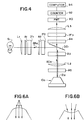
- FIG. 4 A more detailed illustration of an optical system for use with the apparatus according to the invention is shown in Fig. 4.
- Light from a 3200° K tungsten halogen source S1 is collected by a 25 mm focal length plane convex lens L1 which is uncoated.
- the beam diameter throughout the system (above lens L2) is narrowed to 5 mm by apertures A1, A2, A3, and A4.
- Omega Optical Inc. 485/22nm interference filters IF1 and IF2 pass blue excitation light at the wavelength of 463 nm to 507 nm.
- the excitation light 68a is reflected off an Omega 510 dichroic element DCI and which then passes through aperture A3, lens L2 having a focal length of 25 mm, and aperture A5 having an opening of 1 mm.
- a circular spot 0.8 mm in diameter is projected on the radiation port 12a at an incident angle of less than 5.85°.
- fluorescence radiation 80a returns through aperture A5, lens L2, aperture A3, and passes through the dichroic element DCl.
- the beam is narrowed by aperture A4 and wavelengths other than that of interest are blocked by Omega 530/30 nm interference filter IF3.
- Radiation 80a is then focused by lens L3 having a focal length of 30 mm onto a photomultiplier tube 90, model no. 1527 available from Hammamatsu.
- the photomultiplier tube is operated at 800 volts and the output is counted by a counter 92, such as model 1112 photon counter available from the manufacturer EG&G.
- the analog output of the counter 90 is digitized and either plotted or stored in a computer 94.
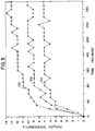
- FIG. 5 An example of three competitive displacement fluorescent immunoassays conducted with the system of Fig. 4 are shown in Fig. 5.
- the three curves 100, 102 and 104 illustrate kinetic displacement in detected photon counts (in hundreds) per second versus time in seconds. All sensors had approximately 2.88 x 10 ⁇ 16 moles/mm2 binding sites. The surface binding site capacity was established by selecting a ratio of nonspecific rabbit IgG to specific anti-digoxin antibody. Antibodies in the selected ratio were attached to the outer wall of the sensor by hydrophobic bonding. All three assays were conducted using 2.93 ng/ml fluoresceinated digoxin conjugate plus a nonlabelled digoxin standard.
- the curve 100 represents use of a standard of 0 ng/ml digoxin
- curve 102 represents use of a digoxin standard of 5.0 ng/ml
- curve 104 represents use of a digoxin standard of 10.0 ng/ml. It can be seen that the greater the concentration of nonlabelled digoxin in the standard, the lower the observed counts, which is the expected result from a competitive immunoassay. The displacement occurs rapidly and can be observed within the first several minutes.
- the radiation port may have a convex surface as shown in Fig. 6A, or a concave surface as shown in Fig. 6B to assist aligning incoming radiation at the desired angle.
- the base portion of the cone may not be used as a support for the cone; the cone could be mounted in any position.
- non-conical sensor shapes are acceptable, such as a pyramid shape having a base with a greater width than that of the radiation port.
- the pyramid can have a base in the form of a regular or nonregular polygon such as a triangle, quadrangle, or any number of sides from two (if the sides are curved) to twenty, or more.
- the walls extend up to converge at a radiation port which distributes the radiation waves evenly about the entire device, that is, over a 360° path.
- the conical shape is preferred, however, because it contains fewer corners and edges at which radiation may escape rather than be totally internally reflected.
- Two or more materials may be used to form the shell, and one or more of the materials may not be transparent to radiation.
- a reactant coating may be disposed on the inner surface instead of, or in addition to, being disposed on the outer surface of the sensor.
- Sensor 10b has outer wall surface 18b and inner wall surface 20b which converge toward each other as they extend away from radiation port 12b.
- the angle of light propagating between converging surfaces 18b, 20b becomes increasingly smaller relative to the critical angle, that is, the angle approaches the critical angle.
- the light signal will exit the sensor 10b when its angle becomes less than the critical angle.
- the converging wall surfaces can be formed along part or all of the length of the sensor 10b to focus the radiation and to increase the mechanical integrity of the shell near the radiation port 12b.
- the sensor 10c has increased wall thickness at the lower portion of the sensor, and therefore increased mechanical integrity in that region.
Landscapes
- Chemical & Material Sciences (AREA)
- Health & Medical Sciences (AREA)
- Physics & Mathematics (AREA)
- Immunology (AREA)
- Analytical Chemistry (AREA)
- Biochemistry (AREA)
- General Health & Medical Sciences (AREA)
- General Physics & Mathematics (AREA)
- Life Sciences & Earth Sciences (AREA)
- Pathology (AREA)
- Nuclear Medicine, Radiotherapy & Molecular Imaging (AREA)
- Engineering & Computer Science (AREA)
- Chemical Kinetics & Catalysis (AREA)
- Plasma & Fusion (AREA)
- Investigating, Analyzing Materials By Fluorescence Or Luminescence (AREA)
- Optical Measuring Cells (AREA)
- Investigating Or Analysing Materials By Optical Means (AREA)
Applications Claiming Priority (2)
| Application Number | Priority Date | Filing Date | Title |
|---|---|---|---|
| US712003 | 1991-06-07 | ||
| US07/712,003 US5156976A (en) | 1991-06-07 | 1991-06-07 | Evanescent wave sensor shell and apparatus |
Publications (2)
| Publication Number | Publication Date |
|---|---|
| EP0519622A2 true EP0519622A2 (fr) | 1992-12-23 |
| EP0519622A3 EP0519622A3 (en) | 1993-05-26 |
Family
ID=24860392
Family Applications (1)
| Application Number | Title | Priority Date | Filing Date |
|---|---|---|---|
| EP19920305121 Withdrawn EP0519622A3 (en) | 1991-06-07 | 1992-06-04 | Evanescent wave sensor shell and apparatus |
Country Status (4)
| Country | Link |
|---|---|
| US (1) | US5156976A (fr) |
| EP (1) | EP0519622A3 (fr) |
| JP (1) | JPH07174692A (fr) |
| CA (1) | CA2069538A1 (fr) |
Cited By (9)
| Publication number | Priority date | Publication date | Assignee | Title |
|---|---|---|---|---|
| DE4307042A1 (de) * | 1993-03-05 | 1994-09-08 | S & L Ges Fuer Wissenschaftlic | Verfahren zum optischen qualitativen und quantitativen Nachweis von Molekülen, Biomolekülen und Mikroorganismen |
| US5557415A (en) * | 1992-05-21 | 1996-09-17 | Faxekalk A/S | Apparatus and method for inducing and detecting fluorescence |
| DE19725050A1 (de) * | 1997-06-13 | 1998-12-17 | Fraunhofer Ges Forschung | Anordnung zur Detektion biochemischer oder chemischer Substanzen mittels Fluoreszenzlichtanregung und Verfahren zu dessen Herstellung |
| EP1204856B1 (fr) * | 1999-08-20 | 2005-07-13 | Stiftung Für Diagnostische Forschung | Procede pour mettre en evidence des substances selon la technique du champ evanescent |
| DE102010041426A1 (de) * | 2010-09-27 | 2012-05-03 | Siemens Aktiengesellschaft | Messeinheit und Verfahren zur optischen Untersuchung einer Flüssigkeit zur Bestimmung einer Analyt-Konzentration |
| DE102007033124B4 (de) * | 2007-07-16 | 2012-12-06 | Fraunhofer-Gesellschaft zur Förderung der angewandten Forschung e.V. | Vorrichtung zur optischen Detektion von Substanzen in einem flüssigen oder gasförmigen Medium |
| DE102018202588A1 (de) * | 2018-02-21 | 2019-08-22 | Robert Bosch Gmbh | Optische Sensorvorrichtung sowie ein Verfahren zur Herstellung einer optischen Sensorvorrichtung |
| DE102018202591A1 (de) * | 2018-02-21 | 2019-08-22 | Robert Bosch Gmbh | Optisches System sowie ein Verfahren zur Herstellung eines optischen Systems |
| DE102021133357A1 (de) | 2021-12-15 | 2023-06-15 | Endress+Hauser Conducta Gmbh+Co. Kg | Sensorelement, Sensorsystem und Verfahren zum Herstellen des Sensorelements |
Families Citing this family (32)
| Publication number | Priority date | Publication date | Assignee | Title |
|---|---|---|---|---|
| US5340715A (en) * | 1991-06-07 | 1994-08-23 | Ciba Corning Diagnostics Corp. | Multiple surface evanescent wave sensor with a reference |
| CA2069537A1 (fr) * | 1991-06-07 | 1992-12-08 | Thomas A. Cook | Systeme d'analyse a sorties multiples utilisant un capteur d'ondes evanescentes |
| US5512492A (en) | 1993-05-18 | 1996-04-30 | University Of Utah Research Foundation | Waveguide immunosensor with coating chemistry providing enhanced sensitivity |
| US5677196A (en) * | 1993-05-18 | 1997-10-14 | University Of Utah Research Foundation | Apparatus and methods for multi-analyte homogeneous fluoro-immunoassays |
| US5919712A (en) | 1993-05-18 | 1999-07-06 | University Of Utah Research Foundation | Apparatus and methods for multi-analyte homogeneous fluoro-immunoassays |
| US5387525A (en) * | 1993-09-03 | 1995-02-07 | Ciba Corning Diagnostics Corp. | Method for activation of polyanionic fluorescent dyes in low dielectric media with quaternary onium compounds |
| US5814565A (en) * | 1995-02-23 | 1998-09-29 | University Of Utah Research Foundation | Integrated optic waveguide immunosensor |
| US5492674A (en) * | 1995-03-17 | 1996-02-20 | Boehringer Mannheim Corporation | Evanescent wave immunoassay system |
| US5745231A (en) * | 1995-06-12 | 1998-04-28 | American Research Corporation Of Virginia | Method of fluorescence analysis comprising evanescent wave excitation and out-of-plane photodetection |
| US5639668A (en) * | 1995-09-14 | 1997-06-17 | Boehringer Mannheim Corporation | Optical apparatus for performing an immunoassay |
| US5854863A (en) * | 1996-03-15 | 1998-12-29 | Erb; Judith | Surface treatment and light injection method and apparatus |
| AU2583797A (en) * | 1996-03-19 | 1997-10-10 | University Of Utah Research Foundation | Oscillation apparatus and methods for multi-analyte homogeneous fluoro-immunoassays |
| DE19628002C1 (de) * | 1996-07-11 | 1997-12-18 | Inst Chemo Biosensorik | Vorrichtung und Verfahren zur Durchführung von Fluoreszenzimmunotests |
| US5832165A (en) | 1996-08-28 | 1998-11-03 | University Of Utah Research Foundation | Composite waveguide for solid phase binding assays |
| US5863790A (en) * | 1997-05-14 | 1999-01-26 | Minnesota Mining And Manfacturing Company | Biological sterility indicator |
| US6025189A (en) * | 1997-05-14 | 2000-02-15 | 3M Innovative Properties Company | Apparatus for reading a plurality of biological indicators |
| US6063591A (en) * | 1997-05-14 | 2000-05-16 | 3M Innovative Properties Company | System for measuring the efficacy of a sterilization cycle |
| US6222619B1 (en) | 1997-09-18 | 2001-04-24 | University Of Utah Research Foundation | Diagnostic device and method |
| SE9803850L (sv) * | 1998-11-11 | 2000-05-12 | Kildal Antenna Consulting Ab | Dielektrisk mikrovågssensor |
| US6300638B1 (en) | 1998-11-12 | 2001-10-09 | Calspan Srl Corporation | Modular probe for total internal reflection fluorescence spectroscopy |
| US6254830B1 (en) | 1999-11-05 | 2001-07-03 | The Board Of Governors For Higher Education, State Of Rhode Island And Providence Plantations | Magnetic focusing immunosensor for the detection of pathogens |
| ATE428918T1 (de) * | 2001-01-23 | 2009-05-15 | Univ Dublin City | Lumineszenz-detektor |
| JP3429282B2 (ja) * | 2001-02-02 | 2003-07-22 | リサーチ・インターナショナル・インコーポレーテッド | 自動化されたシステム、及びサンプルの分析方法 |
| JP2007516413A (ja) * | 2003-06-25 | 2007-06-21 | コーニンクレッカ フィリップス エレクトロニクス エヌ ヴィ | 高感度でエバネッセント場を検出する表面構造を有するサポート |
| JP2008510158A (ja) * | 2004-08-18 | 2008-04-03 | ユニバーシティ オブ バーゼル | 単分子アナライト検出 |
| US7496245B2 (en) * | 2004-08-20 | 2009-02-24 | Research International, Inc. | Misalignment compensating optical sensor and method |
| DE102005026839A1 (de) * | 2005-06-10 | 2006-12-21 | Universität Tübingen | Verfahren und Vorrichtung zur quantitativen Bestimmung von Analyten in flüssigen Proben |
| US7651869B2 (en) * | 2006-03-14 | 2010-01-26 | Research International, Inc. | Optical assay apparatus and methods |
| CA2668421A1 (fr) * | 2008-06-27 | 2009-12-27 | Tyco Healthcare Group Lp | Systeme et methode de detection optique continue de substance a analyser dans la circulation sanguine |
| US8696991B1 (en) | 2010-01-04 | 2014-04-15 | Harold W. Howe | Field deployable surface plasmon resonance based biosensor |
| US10150559B2 (en) | 2015-04-18 | 2018-12-11 | Adtex Inc. | Unmanned flying object and control device therefor |
| WO2018080938A1 (fr) * | 2016-10-25 | 2018-05-03 | Big Sur Scientific, Llc | Systèmes et procédés d'analyse chimique utilisant un spectromètre à réflectance totale atténuée par filtre accordable de fabry-pérot (fptf-atr) |
Family Cites Families (15)
| Publication number | Priority date | Publication date | Assignee | Title |
|---|---|---|---|---|
| FR1480923A (fr) * | 1965-05-24 | 1967-08-09 | ||
| US3604927A (en) * | 1966-11-16 | 1971-09-14 | Block Engineering | Total reflection fluorescence spectroscopy |
| US3669545A (en) * | 1971-05-06 | 1972-06-13 | Wilks Scientific Corp | Apparatus and method for analysis by attenuated total reflection |
| US3733130A (en) * | 1972-03-07 | 1973-05-15 | Atomic Energy Commission | Slotted probe for spectroscopic measurements |
| US4582809A (en) * | 1982-06-14 | 1986-04-15 | Myron J. Block | Apparatus including optical fiber for fluorescence immunoassay |
| US4602869A (en) * | 1983-12-05 | 1986-07-29 | Harrick Nicolas J | Internal reflection prism liquid cell |
| US4978503A (en) * | 1984-06-13 | 1990-12-18 | Ares-Serono Research & Development Limited Partnership | Devices for use in chemical test procedures |
| AT383684B (de) * | 1984-09-17 | 1987-08-10 | Avl Verbrennungskraft Messtech | Anordnung zur fluoreszenzoptischen messung von stoffkonzentrationen in einer probe |
| US4671938A (en) * | 1985-09-09 | 1987-06-09 | Ciba-Corning Diagnostics, Corp. | Immunoassay apparatus |
| US4716121A (en) * | 1985-09-09 | 1987-12-29 | Ord, Inc. | Fluorescent assays, including immunoassays, with feature of flowing sample |
| US4730882A (en) * | 1986-02-10 | 1988-03-15 | Spectra-Tech, Inc. | Multiple internal reflectance spectroscopy system |
| US4852967A (en) * | 1986-03-25 | 1989-08-01 | Ciba Corning Diagnostics Corp. | Evanescent wave sensors |
| AU604364B2 (en) * | 1987-08-13 | 1990-12-13 | Dow Chemical Company, The | Sulfur dioxide removal from gas streams using hydroxyalkyl substituted piperazinones |
| US4893894A (en) * | 1988-04-29 | 1990-01-16 | Mine Safety Appliances Company | Evanescent sensor |
| US5035504A (en) * | 1990-04-23 | 1991-07-30 | Nicolas J. Harrick | Liquid analysis with internal reflection spectroscopy |
-
1991
- 1991-06-07 US US07/712,003 patent/US5156976A/en not_active Expired - Fee Related
-
1992
- 1992-05-26 CA CA002069538A patent/CA2069538A1/fr not_active Abandoned
- 1992-06-04 EP EP19920305121 patent/EP0519622A3/en not_active Withdrawn
- 1992-06-08 JP JP4147348A patent/JPH07174692A/ja not_active Withdrawn
Cited By (13)
| Publication number | Priority date | Publication date | Assignee | Title |
|---|---|---|---|---|
| US5557415A (en) * | 1992-05-21 | 1996-09-17 | Faxekalk A/S | Apparatus and method for inducing and detecting fluorescence |
| DE4307042A1 (de) * | 1993-03-05 | 1994-09-08 | S & L Ges Fuer Wissenschaftlic | Verfahren zum optischen qualitativen und quantitativen Nachweis von Molekülen, Biomolekülen und Mikroorganismen |
| DE19725050A1 (de) * | 1997-06-13 | 1998-12-17 | Fraunhofer Ges Forschung | Anordnung zur Detektion biochemischer oder chemischer Substanzen mittels Fluoreszenzlichtanregung und Verfahren zu dessen Herstellung |
| WO1998057151A1 (fr) * | 1997-06-13 | 1998-12-17 | Fraunhofer-Gesellschaft zur Förderung der angewandten Forschung e.V. | Dispositif de detection de substances chimiques et biochimiques par excitation de lumiere fluorescente et son procede de production |
| DE19725050C2 (de) * | 1997-06-13 | 1999-06-24 | Fraunhofer Ges Forschung | Anordnung zur Detektion biochemischer oder chemischer Substanzen mittels Fluoreszenzlichtanregung und Verfahren zu deren Herstellung |
| US6534011B1 (en) | 1997-06-13 | 2003-03-18 | Fraunhofer-Gesellschaft Zur Forderung Der Angewandten Forschung E.V. | Device for detecting biochemical or chemical substances by fluorescence excitation |
| EP1204856B1 (fr) * | 1999-08-20 | 2005-07-13 | Stiftung Für Diagnostische Forschung | Procede pour mettre en evidence des substances selon la technique du champ evanescent |
| DE102007033124B4 (de) * | 2007-07-16 | 2012-12-06 | Fraunhofer-Gesellschaft zur Förderung der angewandten Forschung e.V. | Vorrichtung zur optischen Detektion von Substanzen in einem flüssigen oder gasförmigen Medium |
| US8877129B2 (en) | 2007-07-16 | 2014-11-04 | Fraunhofer-Gesellschaft Zur Foerderung Der Angewandten Forschung E.V. | Method and device for optical detection of substances in a liquid or gaseous medium |
| DE102010041426A1 (de) * | 2010-09-27 | 2012-05-03 | Siemens Aktiengesellschaft | Messeinheit und Verfahren zur optischen Untersuchung einer Flüssigkeit zur Bestimmung einer Analyt-Konzentration |
| DE102018202588A1 (de) * | 2018-02-21 | 2019-08-22 | Robert Bosch Gmbh | Optische Sensorvorrichtung sowie ein Verfahren zur Herstellung einer optischen Sensorvorrichtung |
| DE102018202591A1 (de) * | 2018-02-21 | 2019-08-22 | Robert Bosch Gmbh | Optisches System sowie ein Verfahren zur Herstellung eines optischen Systems |
| DE102021133357A1 (de) | 2021-12-15 | 2023-06-15 | Endress+Hauser Conducta Gmbh+Co. Kg | Sensorelement, Sensorsystem und Verfahren zum Herstellen des Sensorelements |
Also Published As
| Publication number | Publication date |
|---|---|
| CA2069538A1 (fr) | 1992-12-08 |
| JPH07174692A (ja) | 1995-07-14 |
| US5156976A (en) | 1992-10-20 |
| EP0519622A3 (en) | 1993-05-26 |
Similar Documents
| Publication | Publication Date | Title |
|---|---|---|
| US5156976A (en) | Evanescent wave sensor shell and apparatus | |
| EP0519623B1 (fr) | Système de palpeur avec surfaces multiples pour ondes amorties | |
| EP0075353B1 (fr) | Procédé et dispositif pour la détermination de substances en solution à l'aide d'un guide d'ondes optique | |
| CA1266826A (fr) | Appareil de dosage | |
| US4844869A (en) | Immunoassay apparatus | |
| US6558958B1 (en) | Optical fiber evanescent field excited fluorosensor and method of manufacture | |
| CA1277506C (fr) | Appareil et methode de dosage immunologique par fluorescence | |
| US5350697A (en) | Scattered light detection apparatus | |
| JP3474880B2 (ja) | 免疫分析を行うための光学装置 | |
| Nadeau et al. | High-Q whispering-gallery mode sensor in liquids | |
| US5152962A (en) | Immunoassay apparatus | |
| JPH05504626A (ja) | 化学又は生化学試験に用いる試料セル | |
| JP2000019100A (ja) | Sprセンサセル及びこれを用いた免疫反応測定装置 | |
| CA1339005C (fr) | Methode d'analyse | |
| JP2000356585A (ja) | Sprセンサセル及びこれを用いた免疫反応測定装置 | |
| JP2010521679A (ja) | 流体貯留機構と流体選択機構が一体になったバイオセンサーカートリッジ及びバイオセンサー搭載システム | |
| US7615759B2 (en) | Fluorescence analysis apparatus | |
| JP2000171391A (ja) | Sprセンサセル及びこれを用いた免疫反応測定装置 | |
| JPH1123468A (ja) | 光導波路を使用した固相表面上の蛍光分析装置 | |
| NO161945B (no) | Fremgangsmaate og apparat for bestemmelse av stoffer i opploesning med en optisk boelgeleder. |
Legal Events
| Date | Code | Title | Description |
|---|---|---|---|
| PUAI | Public reference made under article 153(3) epc to a published international application that has entered the european phase |
Free format text: ORIGINAL CODE: 0009012 |
|
| AK | Designated contracting states |
Kind code of ref document: A2 Designated state(s): CH DE ES FR GB IT LI |
|
| PUAL | Search report despatched |
Free format text: ORIGINAL CODE: 0009013 |
|
| AK | Designated contracting states |
Kind code of ref document: A3 Designated state(s): CH DE ES FR GB IT LI |
|
| 17P | Request for examination filed |
Effective date: 19931104 |
|
| 17Q | First examination report despatched |
Effective date: 19950906 |
|
| STAA | Information on the status of an ep patent application or granted ep patent |
Free format text: STATUS: THE APPLICATION IS DEEMED TO BE WITHDRAWN |
|
| 18D | Application deemed to be withdrawn |
Effective date: 19970101 |