EP0520171A1 - Teilnehmerschnittstellenschaltung mit einer Schleifenschlusserkennungsschaltung - Google Patents
Teilnehmerschnittstellenschaltung mit einer Schleifenschlusserkennungsschaltung Download PDFInfo
- Publication number
- EP0520171A1 EP0520171A1 EP92107867A EP92107867A EP0520171A1 EP 0520171 A1 EP0520171 A1 EP 0520171A1 EP 92107867 A EP92107867 A EP 92107867A EP 92107867 A EP92107867 A EP 92107867A EP 0520171 A1 EP0520171 A1 EP 0520171A1
- Authority
- EP
- European Patent Office
- Prior art keywords
- circuit
- current
- amplifiers
- terminals
- line
- Prior art date
- Legal status (The legal status is an assumption and is not a legal conclusion. Google has not performed a legal analysis and makes no representation as to the accuracy of the status listed.)
- Granted
Links
Images

Classifications
-
- H—ELECTRICITY
- H04—ELECTRIC COMMUNICATION TECHNIQUE
- H04M—TELEPHONIC COMMUNICATION
- H04M19/00—Current supply arrangements for telephone systems
- H04M19/02—Current supply arrangements for telephone systems providing ringing current or supervisory tones, e.g. dialling tone or busy tone
- H04M19/026—Arrangements for interrupting the ringing current
Definitions
- This invention relates to telephone circuits, and more particularly, to an electronic subscriber link circuit assembly, i.e. one having an electronic interface between the telephone subscriber line and the telephone exchange, with a circuit for detecting the hook-off condition during the ring step.
- a telephone subscriber sets comprised essentially of a speech circuit and a bell connected in parallel to each other, is connected to a telephone exchange by means of a two-wire line.
- a capacitor Connected in series to the speech circuit which would be only closed on hooking off, and serially to the bell, is a capacitor operative to DC uncouple the bell from the line.
- a telephone subscriber line is supplied a direct voltage from a source, having an alternate voltage source connected serially thereto, which forms the ring signal generator, when the exchange devices control special line connection contacts to close and issue said ring signals to the subscriber.
- the ring signals are sent over the line at predetermined intervals.
- a DC component overlaps the alternate ring current over the line.
- the hook-off condition is detected by circuit means of an electronic type which sense the presence of direct current on the line due to hooking off, even where it overlaps the alternate current of a possible ring signal.
- Ring signals have usually a frequency in the 16 to 66 Hz range and voltage RMS values in the 50 to 105-Volt range, that is, much higher values than those of telephone speech signals.
- the signals are not interrupted directly on hooking off, they are converted, by the speech circuit of the telephone subscriber set, to high-intensity acoustical signals which are harmful to the subscriber's hearing and the set itself. Accordingly, such circuit means are designed to timely sense the hook-off condition and issue an interrupt signal for the ring signals at once to the exchange devices.
- Implemented by electronic means are also other functions required for proper operation of the e network, such as handling the supply of direct current and sending ring signals, switching from two- to four-wire conversion, providing protection from overvoltages, checking the line operability, and so forth.
- These functions are performed by a circuit assembly which forms an interface between the telephone exchange control devices and the telephone subscriber line. This is commonly referred to as the electronic subscriber link or SLIC (Subscriber Line Interface Circuit).
- SLIC Subscriber Line Interface Circuit
- Most of the circuits of the electronic subscriber link are integrated to few, usually two, monolithic IC devices.
- the generator of ring signals is in some instances incorporated to one of the integrated circuits, and in some other instances, is a discrete component serving, as a rule, all of the subscriber lines to the exchange. This invention can be advantageously applied to the last-named situation.
- the hook-off recognition function is performed through the use of a discrete component, resistive network for detecting the line transverse current, and of circuit means internal to one of the integrated circuits to obtain the hook-off information from that current.
- the resistive network consists of six resistors which, for the circuit to operate properly, must be a high-accuracy (1 o/oo) type and are, therefore, relatively expensive, and the internal circuit means obviously require special access terminals for connection to the resistive network.
- Another object is to provide a circuit assembly as above, which can be advantageously implemented with monolithic IC devices having a reduced number of terminals.
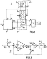
- a supply circuit 5 which comprises a battery or direct voltage source UB having its positive pole connected to the ground connection of the circuit assembly, and a ring current generator in series with the battery UB, being in the form of two identical, push-pull alternate current sources shown at AC.
- Switch-over means such as a relay and respective contacts, generally indicated at 7, are represented by two switches 7A and 7B arranged to connect terminals A and B, respectively, of the telephone line L to the output terminals 3A and 3B of circuit 3 or the terminals of the supply circuit 5.
- the last-named connection is established through two resistors RP having the same resistive value, e.g. 300 ohms, and forming the so-called bridge resistances which, as is known, are required for the coupling at the exchange between the supply circuit and the subscriber line.
- the resistive network formed of these four resistors and the two bridge resistors is effective to separate the so-called transverse current, i.e. the useful component of the line current, from the so-called longitudinal current, i.e. the component from noise and stray phenomena.
- transverse current i.e. the useful component of the line current
- longitudinal current i.e. the component from noise and stray phenomena.
- the network operation is based on that the transverse current flows in opposite directions through the two resistors RP, whereas the longitudinal current flows in the same direction through both of them.
- the six resistors in the network should be all carefully sorted out such that their coupling can be a highly accurate one.
- the transverse current information thus revealed is processed within the circuit 3 by circuit means adapted to obtain information about a possible hook-off condition of the subscriber set U with the line L connected to the supply circuit 5 as a call or ring signal is being sent.
- circuit means will recognize the presence of a DC component in the transverse current and send a signal to the exchange control devices whereby the ring signal is discontinued and the line of the calling subscriber is put through that of the called subscriber.
- FIG 2 where similar elements to those in Figure 1 are denoted by just the same references and comparable ones by the same references primed, illustrates a circuit assembly according to the invention.
- the supply circuit 5' is a so-called unbalanced bell type, that is one in which the ring generator consists of a single alternate current source AC' and is, from the functional standpoint, the equivalent of the conventional one with two push-pull sources.
- This construction for the power supply is preferable in that it affords a simpler circuitry, but in principle, the invention could be also practiced with a conventional balanced bell supply, as explained hereinafter with reference to Figure 5.
- the bridge resistors are connected, the one RP, between one contact of the switch 7B and the supply circuit 5', specifically the negative terminal of the battery UB through the source AC', in series, similarly to the circuit of Figure 1, and the other RP', between the line terminal A and the output terminal 3A of circuit 3'.
- An additional resistor RA is connected between the line terminal B and the output terminal 3B of circuit 3'.
- the resistive value of resistor RA should be much higher than that of resistors RP, for example equal to 4 kOhms, for a reason to be explained.
- the terminals 3A and 3B of circuit 3' are the output terminals of two bridge-connected operational amplifiers in a buffer configuration. This construction of the output stage of circuit 3' allows the line current flowing through the stage output terminals 3A and 3B to be detected. With that, moreover, the output terminal 3A will be, during the ring step, at a DC potential a few volts below ground level (typically 5 Volts), and the output terminal 3B will be at a potential a few volts above battery UB voltage (typically 5 Volts).
- the line current information which in the conventional circuit of Figure 1 was obtained through the net 6 of six precision resistors, according to the invention, it is obtained directly from the final stage of the interface circuit 3' which is coupled, as shown, to the telephone line L even with the latter connected to the supply circuit 5', via the bridge resistor RP' and the additional resistor RA.
- the resistive value of the last-named resistor is sufficiently large not to significantly alter the desired level for the ring signal unused on the subscriber line, but still capable of supplying on terminal 3B the required line current information.
- the final stage of circuit 3' may be illustrated schematically by two operational amplifiers, indicated at 9A and 9B in Figure 2, which have their respective inverting inputs connected to the respective outputs 3A and 3B, and the non-inverting terminals biased to a voltage value VA slightly below ground and a voltage value VB slightly above battery UB voltage, respectively.
- a circuit block 15, e.g. of the kind described in Patent Application No. 19983-A/85, filed on 03.20.85 by SGS Microelettronica S.p.A., is connected to the amplifiers 9A and 9B so as to obtain, from currents IA and IB as by add and subtract operations, a current kIT which is the mirror image of the transverse current IT.
- a detection circuit indicated at 17 in Figure 2, which obtains, from the image of the transverse current IT, information of the presence of a DC component on the line current, and accordingly, detects any hook-offs and sends a corresponding signal (OH) to the exchange control devices.
- resistor RA is not strictly required. In fact, with ring voltage values below 60 Volts RMS, or more generally, with any value of the ring voltage where high-precision sensing circuits are employed, it is not necessary that current IB be other than zero, since the current IT information may be alternatively obtained from just current IA by virtue of the detection being carried out by performing the half-sum of currents IA and IB.
- the hook-off detecting circuit 17 may be a conventional one, such as that disclosed in Italian Patent No. 1,212,838 to this Applicant, but could be advantageously configured as shown diagramatically in Figure 3.
- a logic circuit LG will receiver from the exchange control devices, a ring command signal RC and, as a result, cause a switch 8, in series with the input of a transconductance operational amplifier OTA, to make.
- the latter has a transfer characteristic of the kind illustrated by Figure 4, that is outputs a current ICRT which is proportional to the input current IIN, for values of this current falling between two given threshold values, and maintained constant at a positive or negative value Io as the input current varies, upon attaining such values.
- the mean value of current kIT Prior to hooking off, the mean value of current kIT would be less than the threshold current IS, and accordingly, the capacitor CRT left in the discharged state.
- the mean value of kIT Upon hooking off, due to the direct current which overlaps the ring alternate current, the mean value of kIT will exceed the threshold current IS, and the capacitor CRT become charged.
- the output of the circuit OTA is connected to the input of a comparator CP which has another input at a predetermined reference voltage VREF and its output connected to the logic circuit LG. On the voltage across the capacitor CRT exceeding the value of the reference voltage VREF, the comparator CP will send a signal to the logic circuit LG, which transmits a hook-off condition signal OH to the exchange control devices.
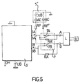
- FIG. 5 Shown in Figure 5, where similar elements to those in Figure 2 are denoted by the same references, is a circuit assembly according to the invention, wherein the ring signal is supplied by two identical, push-pull AC sources being both designated AC.
- This circuit differs from the one shown in Figure 2 by that the bridge resistor, here designated RP'' and relating to the line terminal A, is connected to the supply circuit 5'' through contact 7A, as was the case with the conventional circuit in Figure 1, and in that a second resistor RA', having the same resistive value as RA, is connected between the terminal A and the output 3A of circuit 3'.
- the bridge resistor here designated RP'' and relating to the line terminal A
- the line current information is supplied through the two resistors RA and RA', and the above-described characteristic of circuit 3' is utilized whereby the terminals 3A and 3B are, during the ring step, at voltages close to ground and negative battery pole levels, respectively.
- the resistors RA and RA' are both required at all times.
- the circuit assembly of this invention fully achieves its objects.
- it requires no discrete high-precision resistors to detect the line current, since it utilizes current information already present on the interface circuit, and hence, no dedicated electrical connections between external components and the interface circuit.
- the latter can be advantageously integrated with a reduced number of terminals.
- the few additional discrete components involved, which as explained are not invariably necessary, are no critical values, and form, therefore, low-cost components.
Landscapes
- Engineering & Computer Science (AREA)
- Signal Processing (AREA)
- Interface Circuits In Exchanges (AREA)
- Devices For Supply Of Signal Current (AREA)
- Emergency Protection Circuit Devices (AREA)
- Exchange Systems With Centralized Control (AREA)
- Telephonic Communication Services (AREA)
Applications Claiming Priority (2)
| Application Number | Priority Date | Filing Date | Title |
|---|---|---|---|
| ITMI911748 | 1991-06-25 | ||
| ITMI911748A IT1248549B (it) | 1991-06-25 | 1991-06-25 | Complesso circuitale telefonico ad attacco d'utente elettronico con circuito per la rivelazione dello sgancio in fase di suoneria a numerodi componenti ridotto. |
Publications (2)
| Publication Number | Publication Date |
|---|---|
| EP0520171A1 true EP0520171A1 (de) | 1992-12-30 |
| EP0520171B1 EP0520171B1 (de) | 1997-02-05 |
Family
ID=11360202
Family Applications (1)
| Application Number | Title | Priority Date | Filing Date |
|---|---|---|---|
| EP92107867A Expired - Lifetime EP0520171B1 (de) | 1991-06-25 | 1992-05-11 | Teilnehmerschnittstellenschaltung mit einer Schleifenschlusserkennungsschaltung |
Country Status (11)
| Country | Link |
|---|---|
| US (1) | US5402484A (de) |
| EP (1) | EP0520171B1 (de) |
| JP (1) | JPH05167678A (de) |
| KR (1) | KR100263659B1 (de) |
| CN (1) | CN1030365C (de) |
| AT (1) | ATE148818T1 (de) |
| BR (1) | BR9202108A (de) |
| CA (1) | CA2068971C (de) |
| DE (1) | DE69217279T2 (de) |
| IT (1) | IT1248549B (de) |
| TW (1) | TW199951B (de) |
Cited By (2)
| Publication number | Priority date | Publication date | Assignee | Title |
|---|---|---|---|---|
| EP0724348A1 (de) * | 1995-01-30 | 1996-07-31 | Harris Corporation | Verfahren und Schaltungsanordnung zur eigensicheren Abhebeerkennung bei Telefonsystemstörung |
| EP0760576A1 (de) * | 1995-08-30 | 1997-03-05 | Harris Corporation | Integrierte Rufanschlussschaltung und -verfahren |
Families Citing this family (1)
| Publication number | Priority date | Publication date | Assignee | Title |
|---|---|---|---|---|
| EP0651541B1 (de) * | 1993-10-29 | 2001-01-10 | STMicroelectronics S.r.l. | Fernsprech-Teilnehmerschaltung mit einem galvanischen Trennungselement zur Erzeugung der An/Aus Zustände einer Fernsprechleitung |
Citations (3)
| Publication number | Priority date | Publication date | Assignee | Title |
|---|---|---|---|---|
| EP0073462A2 (de) * | 1981-08-27 | 1983-03-09 | Siemens Aktiengesellschaft | Teilnehmeranschlussschaltung |
| US4473719A (en) * | 1982-05-17 | 1984-09-25 | At&T Bell Laboratories | Switchhook status detector |
| CH675803A5 (en) * | 1988-05-19 | 1990-10-31 | Siemens Ag Albis | Call signal disconnection circuit for telephone network - uses superimposed DC signal fed via amplifier to threshold switch |
Family Cites Families (11)
| Publication number | Priority date | Publication date | Assignee | Title |
|---|---|---|---|---|
| GB1479094A (en) * | 1975-03-25 | 1977-07-06 | Standard Telephones Cables Ltd | Ring trip detectors |
| US4396805A (en) * | 1981-09-21 | 1983-08-02 | Siemens Corporation | Ring trip detector for a subscriber line interface circuit |
| US4524245A (en) * | 1983-01-13 | 1985-06-18 | Redcom Laboratories Inc. | Ring trip detection system |
| US4866768A (en) * | 1985-06-26 | 1989-09-12 | Siemens Corporate Research & Support, Inc. | Station line interface circuit for a telecommunication network |
| JPH0671295B2 (ja) * | 1987-04-06 | 1994-09-07 | 沖電気工業株式会社 | 加入者線給電回路 |
| CA1291835C (en) * | 1987-06-19 | 1991-11-05 | Toshiro Tojo | Ring trip circuit for subscriber telephone |
| FR2631765B1 (fr) * | 1988-05-20 | 1990-08-31 | Dolphin Integration Sa | Circuit d'interface telephonique |
| US5189697A (en) * | 1990-04-30 | 1993-02-23 | Northern Telecom Limited | Line interface circuit |
| DE4019365A1 (de) * | 1990-06-18 | 1991-12-19 | Philips Patentverwaltung | Schaltungsanordnung fuer ein teilnehmergeraet |
| US5133006A (en) * | 1990-10-31 | 1992-07-21 | Seiscor Technologies Inc. | Combination interface circuit for coupling a digital loop carrier telephone system |
| JPH05268336A (ja) * | 1992-03-19 | 1993-10-15 | Fujitsu Ltd | リングトリップ回路 |
-
1991
- 1991-06-25 IT ITMI911748A patent/IT1248549B/it active IP Right Grant
-
1992
- 1992-05-11 EP EP92107867A patent/EP0520171B1/de not_active Expired - Lifetime
- 1992-05-11 DE DE69217279T patent/DE69217279T2/de not_active Expired - Fee Related
- 1992-05-11 AT AT92107867T patent/ATE148818T1/de not_active IP Right Cessation
- 1992-05-12 TW TW081103655A patent/TW199951B/zh active
- 1992-05-15 CN CN92103695A patent/CN1030365C/zh not_active Expired - Fee Related
- 1992-05-19 CA CA002068971A patent/CA2068971C/en not_active Expired - Fee Related
- 1992-05-29 US US07/891,548 patent/US5402484A/en not_active Expired - Lifetime
- 1992-06-01 JP JP4140551A patent/JPH05167678A/ja active Pending
- 1992-06-02 BR BR929202108A patent/BR9202108A/pt not_active Application Discontinuation
- 1992-06-17 KR KR1019920010462A patent/KR100263659B1/ko not_active Expired - Fee Related
Patent Citations (3)
| Publication number | Priority date | Publication date | Assignee | Title |
|---|---|---|---|---|
| EP0073462A2 (de) * | 1981-08-27 | 1983-03-09 | Siemens Aktiengesellschaft | Teilnehmeranschlussschaltung |
| US4473719A (en) * | 1982-05-17 | 1984-09-25 | At&T Bell Laboratories | Switchhook status detector |
| CH675803A5 (en) * | 1988-05-19 | 1990-10-31 | Siemens Ag Albis | Call signal disconnection circuit for telephone network - uses superimposed DC signal fed via amplifier to threshold switch |
Non-Patent Citations (1)
| Title |
|---|
| IEEE JOURNAL OF SOLID-STATE CIRCUITS vol. SC-18, no. 6, December 1983, NEW YORK, USA pages 665 - 677; SIRSI ET AL.: 'Integrated Electronic Subscriber Line Interface Circuit with Ringing on Chip' * |
Cited By (2)
| Publication number | Priority date | Publication date | Assignee | Title |
|---|---|---|---|---|
| EP0724348A1 (de) * | 1995-01-30 | 1996-07-31 | Harris Corporation | Verfahren und Schaltungsanordnung zur eigensicheren Abhebeerkennung bei Telefonsystemstörung |
| EP0760576A1 (de) * | 1995-08-30 | 1997-03-05 | Harris Corporation | Integrierte Rufanschlussschaltung und -verfahren |
Also Published As
| Publication number | Publication date |
|---|---|
| ATE148818T1 (de) | 1997-02-15 |
| KR100263659B1 (ko) | 2000-08-01 |
| CN1030365C (zh) | 1995-11-22 |
| DE69217279D1 (de) | 1997-03-20 |
| BR9202108A (pt) | 1993-02-02 |
| JPH05167678A (ja) | 1993-07-02 |
| ITMI911748A1 (it) | 1992-12-25 |
| TW199951B (de) | 1993-02-11 |
| CN1068229A (zh) | 1993-01-20 |
| CA2068971C (en) | 2002-01-22 |
| ITMI911748A0 (it) | 1991-06-25 |
| EP0520171B1 (de) | 1997-02-05 |
| DE69217279T2 (de) | 1997-05-28 |
| IT1248549B (it) | 1995-01-19 |
| CA2068971A1 (en) | 1992-12-26 |
| US5402484A (en) | 1995-03-28 |
Similar Documents
| Publication | Publication Date | Title |
|---|---|---|
| EP0323516B1 (de) | Rufabschaltungserkennungsschaltung für telefonteilnehmer | |
| EP0212632B1 (de) | Teilnehmerschnittstellenschaltung | |
| US4447675A (en) | Ring-trip detector | |
| EP0617533A2 (de) | Gerät und Verfahren zur Zustandserkennung einer Fernsprechleitung | |
| EP0520171B1 (de) | Teilnehmerschnittstellenschaltung mit einer Schleifenschlusserkennungsschaltung | |
| EP0520156B1 (de) | Strombegrenzte Teilnehmerschnittstellenschaltung | |
| US5289537A (en) | On-hook transmission circuit in cable line | |
| US5636274A (en) | Switch controller and method | |
| US4459433A (en) | Station identification circuit arrangement | |
| CA1311570C (en) | Apparatus for testing spare line circuits in a communication system | |
| EP0056810A1 (de) | Schleifendetektionsschaltung zur verwendung in der schnittstelle einer teilnehmerschleife | |
| US4369337A (en) | Central office interface circuit | |
| US4167656A (en) | Junctor checking system | |
| US3894192A (en) | DX signaling circuit | |
| US6944286B1 (en) | Ground key detection circuit and method for interference-resistant detection of the activation of a ground key for telephones | |
| JP3097626B2 (ja) | 加入者線監視回路 | |
| KR100238541B1 (ko) | 사설교환기의 과금신호 처리장치 | |
| US3467787A (en) | Circuit arrangement to supervise telecommunication and particularly telephone lines | |
| US5500896A (en) | Code converter comprising protection circuit | |
| EP0455335A1 (de) | Schnittstellenschaltung für Teilnehmerleitung | |
| JPS61145947A (ja) | リングトリツプ回路 | |
| JPH0415657B2 (de) | ||
| JPS6139696A (ja) | 通話電流検出回路 | |
| JPS5860861A (ja) | 電話応答装置の監視装置 | |
| JPS625758A (ja) | 電話回線電圧検出回路 |
Legal Events
| Date | Code | Title | Description |
|---|---|---|---|
| PUAI | Public reference made under article 153(3) epc to a published international application that has entered the european phase |
Free format text: ORIGINAL CODE: 0009012 |
|
| AK | Designated contracting states |
Kind code of ref document: A1 Designated state(s): AT BE CH DE DK ES FR GB GR IT LI LU MC NL PT SE |
|
| 17P | Request for examination filed |
Effective date: 19930217 |
|
| 17Q | First examination report despatched |
Effective date: 19950530 |
|
| GRAG | Despatch of communication of intention to grant |
Free format text: ORIGINAL CODE: EPIDOS AGRA |
|
| GRAH | Despatch of communication of intention to grant a patent |
Free format text: ORIGINAL CODE: EPIDOS IGRA |
|
| GRAH | Despatch of communication of intention to grant a patent |
Free format text: ORIGINAL CODE: EPIDOS IGRA |
|
| GRAA | (expected) grant |
Free format text: ORIGINAL CODE: 0009210 |
|
| AK | Designated contracting states |
Kind code of ref document: B1 Designated state(s): AT BE CH DE DK ES FR GB GR IT LI LU MC NL PT SE |
|
| PG25 | Lapsed in a contracting state [announced via postgrant information from national office to epo] |
Ref country code: NL Free format text: LAPSE BECAUSE OF FAILURE TO SUBMIT A TRANSLATION OF THE DESCRIPTION OR TO PAY THE FEE WITHIN THE PRESCRIBED TIME-LIMIT Effective date: 19970205 Ref country code: LI Effective date: 19970205 Ref country code: GR Free format text: LAPSE BECAUSE OF FAILURE TO SUBMIT A TRANSLATION OF THE DESCRIPTION OR TO PAY THE FEE WITHIN THE PRESCRIBED TIME-LIMIT Effective date: 19970205 Ref country code: ES Free format text: THE PATENT HAS BEEN ANNULLED BY A DECISION OF A NATIONAL AUTHORITY Effective date: 19970205 Ref country code: DK Effective date: 19970205 Ref country code: CH Effective date: 19970205 Ref country code: BE Effective date: 19970205 Ref country code: AT Effective date: 19970205 |
|
| REF | Corresponds to: |
Ref document number: 148818 Country of ref document: AT Date of ref document: 19970215 Kind code of ref document: T |
|
| ITF | It: translation for a ep patent filed | ||
| REG | Reference to a national code |
Ref country code: CH Ref legal event code: EP |
|
| REF | Corresponds to: |
Ref document number: 69217279 Country of ref document: DE Date of ref document: 19970320 |
|
| ET | Fr: translation filed | ||
| PG25 | Lapsed in a contracting state [announced via postgrant information from national office to epo] |
Ref country code: SE Effective date: 19970505 Ref country code: PT Effective date: 19970505 |
|
| PG25 | Lapsed in a contracting state [announced via postgrant information from national office to epo] |
Ref country code: LU Free format text: LAPSE BECAUSE OF NON-PAYMENT OF DUE FEES Effective date: 19970531 |
|
| NLV1 | Nl: lapsed or annulled due to failure to fulfill the requirements of art. 29p and 29m of the patents act | ||
| REG | Reference to a national code |
Ref country code: CH Ref legal event code: PL |
|
| PG25 | Lapsed in a contracting state [announced via postgrant information from national office to epo] |
Ref country code: MC Effective date: 19971130 |
|
| PLBE | No opposition filed within time limit |
Free format text: ORIGINAL CODE: 0009261 |
|
| STAA | Information on the status of an ep patent application or granted ep patent |
Free format text: STATUS: NO OPPOSITION FILED WITHIN TIME LIMIT |
|
| 26N | No opposition filed | ||
| REG | Reference to a national code |
Ref country code: GB Ref legal event code: IF02 |
|
| PGFP | Annual fee paid to national office [announced via postgrant information from national office to epo] |
Ref country code: DE Payment date: 20020516 Year of fee payment: 11 |
|
| PG25 | Lapsed in a contracting state [announced via postgrant information from national office to epo] |
Ref country code: DE Free format text: LAPSE BECAUSE OF NON-PAYMENT OF DUE FEES Effective date: 20031202 |
|
| PGFP | Annual fee paid to national office [announced via postgrant information from national office to epo] |
Ref country code: GB Payment date: 20040505 Year of fee payment: 13 |
|
| PGFP | Annual fee paid to national office [announced via postgrant information from national office to epo] |
Ref country code: FR Payment date: 20040510 Year of fee payment: 13 |
|
| PG25 | Lapsed in a contracting state [announced via postgrant information from national office to epo] |
Ref country code: IT Free format text: LAPSE BECAUSE OF NON-PAYMENT OF DUE FEES Effective date: 20050511 Ref country code: GB Free format text: LAPSE BECAUSE OF NON-PAYMENT OF DUE FEES Effective date: 20050511 |
|
| GBPC | Gb: european patent ceased through non-payment of renewal fee |
Effective date: 20050511 |
|
| PG25 | Lapsed in a contracting state [announced via postgrant information from national office to epo] |
Ref country code: FR Free format text: LAPSE BECAUSE OF NON-PAYMENT OF DUE FEES Effective date: 20060131 |
|
| REG | Reference to a national code |
Ref country code: FR Ref legal event code: ST Effective date: 20060131 |