EP0520175A1 - Buse avec dispositif auxiliaire pour aspirateur - Google Patents
Buse avec dispositif auxiliaire pour aspirateur Download PDFInfo
- Publication number
- EP0520175A1 EP0520175A1 EP92108007A EP92108007A EP0520175A1 EP 0520175 A1 EP0520175 A1 EP 0520175A1 EP 92108007 A EP92108007 A EP 92108007A EP 92108007 A EP92108007 A EP 92108007A EP 0520175 A1 EP0520175 A1 EP 0520175A1
- Authority
- EP
- European Patent Office
- Prior art keywords
- housing
- vacuum cleaner
- drive
- cleaner nozzle
- brush roller
- Prior art date
- Legal status (The legal status is an assumption and is not a legal conclusion. Google has not performed a legal analysis and makes no representation as to the accuracy of the status listed.)
- Granted
Links
Images


Classifications
-
- A—HUMAN NECESSITIES
- A47—FURNITURE; DOMESTIC ARTICLES OR APPLIANCES; COFFEE MILLS; SPICE MILLS; SUCTION CLEANERS IN GENERAL
- A47L—DOMESTIC WASHING OR CLEANING; SUCTION CLEANERS IN GENERAL
- A47L9/00—Details or accessories of suction cleaners, e.g. mechanical means for controlling the suction or for effecting pulsating action; Storing devices specially adapted to suction cleaners or parts thereof; Carrying-vehicles specially adapted for suction cleaners
- A47L9/02—Nozzles
- A47L9/04—Nozzles with driven brushes or agitators
- A47L9/0405—Driving means for the brushes or agitators
- A47L9/0416—Driving means for the brushes or agitators driven by fluid pressure, e.g. by means of an air turbine
-
- A—HUMAN NECESSITIES
- A47—FURNITURE; DOMESTIC ARTICLES OR APPLIANCES; COFFEE MILLS; SPICE MILLS; SUCTION CLEANERS IN GENERAL
- A47L—DOMESTIC WASHING OR CLEANING; SUCTION CLEANERS IN GENERAL
- A47L9/00—Details or accessories of suction cleaners, e.g. mechanical means for controlling the suction or for effecting pulsating action; Storing devices specially adapted to suction cleaners or parts thereof; Carrying-vehicles specially adapted for suction cleaners
- A47L9/02—Nozzles
- A47L9/04—Nozzles with driven brushes or agitators
- A47L9/0427—Gearing or transmission means therefor
- A47L9/0444—Gearing or transmission means therefor for conveying motion by endless flexible members, e.g. belts
Definitions
- the invention relates to an active vacuum cleaner nozzle mentioned in the preamble of claim 1.
- the present invention relates specifically to a vacuum cleaner nozzle with an additional, driven brush roller.
- the invention has for its object to provide an active vacuum cleaner nozzle of the type described above, which enables convenient, user-friendly maintenance and accessibility of the entire nozzle interior with all of its functional elements.
- the upper housing part is pivotally articulated on the lower housing part of the two-part nozzle housing in such a way that the upper housing part can be pivoted between a releasably lockable first position which closes the inside of the housing and a second position which exposes the brush roller, the transmission and the drive inside is.
- the intake manifold connection piece is pivotably articulated on the lower housing part between a first position that locks the upper housing part and a second position that unlocks the upper housing part in such a way that the pivoting position of the intake manifold connection piece unlocking the upper part of the nozzle housing lies in a swivel angle range that is outside of the intended working mode the swivel angle required for the nozzle.
- This type of housing locking eliminates the need for structurally complex and cost-increasing additional locking mechanisms, as well as inexpensive, but less stable, resilient snap locks.
- a spring stop that can be overcome is provided at the end of the swivel angle range required for the working mode and before the start of the swivel angle range of the intake manifold connection opening.
- these are functionally dimensioned and cooperatively positioned flat ribs on the sliding surfaces of the locking mechanism.
- such locking points can also be realized by spring-loaded locking balls or in any other known manner.
- this locking of the upper part of the nozzle housing is designed in the manner of a surface seal with wide, complementary overlapping locking surfaces by the swivel bearing block of the intake manifold connection piece.
- this swivel bearing area of the intake manifold connection piece is preferably also simultaneously formed as part of a drive housing, especially as part of the turbine housing, generally as a cylinder jacket segment with an opening to the intake pipe connection piece.
- the swivel bearing block of the intake manifold connection piece is configured so as to be so, overall specifically as a hollow cylinder cutout that it simultaneously fulfills three functions, namely the swivel mounting of the intake pipe connection piece, freely pivotable part of the drive housing, especially the turbine housing of the brush roller drive and finally the upper part of the nozzle housing is pneumatically sealed.
- the active vacuum cleaner nozzle shown in FIG. 1 in the form of a schematic line drawing consists of a two-part housing 2, 3 provided with a suction pipe connection piece 1, in which a brush roller 4, a drive 5 and a gear 6 are arranged.
- the drive 5 is designed as a turbine and the gear 6 as a toothed belt drive.
- the upper housing part is articulated on the lower housing part 3 via a pivot bearing, which is explained in more detail in FIG. 3, coaxially to the axis 7 of the brush roller 4.
- Fig. 1 the upper housing part is shown in a central pivot position, that is, in a partially open position, which does not yet correspond to the full opening, but also does not correspond to the locked state.
- the upper part of the nozzle housing 2 is pivoted further in the direction of arrow 8 and then, in the end position finally defined by means of a stop, completely releases the interior of the nozzle housing for engagement from above with all its functional parts.
- the upper housing part 2 is pivoted against the direction of the arrow 8 until the folded lower edge 10 of the upper housing part lies flush with the complementary folded upper edge 9 of the lower housing part 3.
- the intake edge connection-side end edge 11 of the housing upper part 2 swings freely past the brush edge on the front edge 12 of the bearing block 13 designed in the manner of a hollow cylinder segment, to the extent that the outer edge 14 of the housing is just flush with the complementary cylindrical inner wall surface 15 of the bearing block 13 of the intake manifold connector 1 is.
- the intake manifold connection piece 1 is pivoted in the direction of arrow 8 in such a way that the complementary cylindrical surfaces 14 and 15 of the upper housing part 2 or of the intake pipe connection piece 1 slide flush on one another.
- a projecting transverse rib 16 and a transverse rib 15 projecting in the same way on the cylindrical jacket surface 15 of the intake manifold connection piece 1 are formed on the cylinder surface 14 of the upper housing part 2, which for the purpose of clarifying the function in FIG. 1 are enlarged and are not shown to scale.
- transverse ribs 16, 17 are dimensioned such that, on the one hand, they mark a sufficiently effective and clearly noticeable stop and pressure point in the transition area between the swivel angle area used in the working mode and the swivel angle area of the intake manifold connection piece 1 that unlocks the upper part 2 of the housing, but on the other hand they can be overcome non-destructively by elastic means.
- the vacuum cleaner nozzle shown as an exemplary embodiment in the figures runs on a pair of front rollers 18 and a pair of rear rollers 19.
- the upper housing part 2, the brush roller 4 and the front rollers 18 coaxially rotatable about a pivot or rotation axis 7, while the journals for the rear rollers 19 and the pivot bearing for the intake manifold connection piece 1 are also arranged coaxially on an axis of rotation or pivot axis 20.
- the drive for the brush roller 4 is designed in the form of a twin turbine with a right-hand turbine impeller 5 ′ and a left-hand turbine impeller 5 ′′, which run on a common bearing shaft 21.
- the torque that can be picked up by this twin turbine drive 5 '5' 'on the shaft 21 is transmitted via a rubber toothed belt 22 from the center between the two turbine wheels 5' 5 '' to a central coupling 23 on the brush roller 4.
- the toothed belt drive 6 is completely encapsulated in a channel-like gear housing 24, which is horizontally separated at least essentially in the center and sealed by complementary folds with one part integral part of the lower housing part 3 of the suction nozzle and with its upper part an integral part of the upper housing part 2 of the suction nozzle .
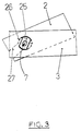
- the upper housing part 2 can be seen in the schematic, function-explaining FIG. 3, via a sliding pin 25 which is designed in the manner of a sliding block and which is fixed in a rotationally fixed manner to the lower housing part 3 and an open round hole / elongated hole combination 26, 27 which is formed in the upper housing part 2, so on the lower part 3 hinged that the upper housing part 2 is freely removable from the lower housing part 3 in the open position.
- a sliding pin 25 which is designed in the manner of a sliding block and which is fixed in a rotationally fixed manner to the lower housing part 3 and an open round hole / elongated hole combination 26, 27 which is formed in the upper housing part 2, so on the lower part 3 hinged that the upper housing part 2 is freely removable from the lower housing part 3 in the open position.
Landscapes
- Engineering & Computer Science (AREA)
- Mechanical Engineering (AREA)
- Nozzles For Electric Vacuum Cleaners (AREA)
- Jet Pumps And Other Pumps (AREA)
Applications Claiming Priority (2)
| Application Number | Priority Date | Filing Date | Title |
|---|---|---|---|
| DE4121130A DE4121130A1 (de) | 1991-06-26 | 1991-06-26 | Aktive staubsaugerduese |
| DE4121130 | 1991-06-26 |
Publications (2)
| Publication Number | Publication Date |
|---|---|
| EP0520175A1 true EP0520175A1 (fr) | 1992-12-30 |
| EP0520175B1 EP0520175B1 (fr) | 1995-10-11 |
Family
ID=6434799
Family Applications (1)
| Application Number | Title | Priority Date | Filing Date |
|---|---|---|---|
| EP92108007A Expired - Lifetime EP0520175B1 (fr) | 1991-06-26 | 1992-05-12 | Buse avec dispositif auxiliaire pour aspirateur |
Country Status (3)
| Country | Link |
|---|---|
| EP (1) | EP0520175B1 (fr) |
| AT (1) | ATE128832T1 (fr) |
| DE (2) | DE4121130A1 (fr) |
Cited By (4)
| Publication number | Priority date | Publication date | Assignee | Title |
|---|---|---|---|---|
| EP0650689A1 (fr) * | 1993-11-02 | 1995-05-03 | Rexair, Inc | Instrument de nettoyage à collecteur démontable |
| WO1996035367A1 (fr) * | 1995-05-13 | 1996-11-14 | Vorwerk & Co. Interholding Gmbh | Dispositif de montage pour une brosse ou equipe d'une brosse pour un appareil de nettoyage du sol |
| US6513190B1 (en) | 2000-04-21 | 2003-02-04 | The Hoover Company | Turbine powered vacuum cleaner nozzle |
| EP3222185A4 (fr) * | 2015-12-10 | 2018-06-13 | Jiangsu Midea Cleaning Appliances Co., Ltd. | Ensemble brosse à plancher pour aspirateur vertical et aspirateur vertical comprenant celui-ci |
Citations (4)
| Publication number | Priority date | Publication date | Assignee | Title |
|---|---|---|---|---|
| DE1243346B (de) * | 1959-03-06 | 1967-06-29 | Preco Inc | Luftturbine fuer den Antrieb eines Reinigungswerkzeuges in einem Staubsaugermundstueck |
| EP0061826A1 (fr) * | 1981-03-26 | 1982-10-06 | Black & Decker Inc. | Buse d'aspirateur pour utilisation sur surfaces horizontales et verticales |
| EP0313403A2 (fr) * | 1987-10-23 | 1989-04-26 | Matsushita Electric Industrial Co., Ltd. | Suceur d'un aspirateur de poussières |
| EP0381015A1 (fr) * | 1989-01-31 | 1990-08-08 | Fedag | Tuyère d'aspiration à fonction multiple |
-
1991
- 1991-06-26 DE DE4121130A patent/DE4121130A1/de not_active Withdrawn
-
1992
- 1992-05-12 AT AT92108007T patent/ATE128832T1/de not_active IP Right Cessation
- 1992-05-12 DE DE59203957T patent/DE59203957D1/de not_active Expired - Fee Related
- 1992-05-12 EP EP92108007A patent/EP0520175B1/fr not_active Expired - Lifetime
Patent Citations (4)
| Publication number | Priority date | Publication date | Assignee | Title |
|---|---|---|---|---|
| DE1243346B (de) * | 1959-03-06 | 1967-06-29 | Preco Inc | Luftturbine fuer den Antrieb eines Reinigungswerkzeuges in einem Staubsaugermundstueck |
| EP0061826A1 (fr) * | 1981-03-26 | 1982-10-06 | Black & Decker Inc. | Buse d'aspirateur pour utilisation sur surfaces horizontales et verticales |
| EP0313403A2 (fr) * | 1987-10-23 | 1989-04-26 | Matsushita Electric Industrial Co., Ltd. | Suceur d'un aspirateur de poussières |
| EP0381015A1 (fr) * | 1989-01-31 | 1990-08-08 | Fedag | Tuyère d'aspiration à fonction multiple |
Cited By (6)
| Publication number | Priority date | Publication date | Assignee | Title |
|---|---|---|---|---|
| EP0650689A1 (fr) * | 1993-11-02 | 1995-05-03 | Rexair, Inc | Instrument de nettoyage à collecteur démontable |
| WO1996035367A1 (fr) * | 1995-05-13 | 1996-11-14 | Vorwerk & Co. Interholding Gmbh | Dispositif de montage pour une brosse ou equipe d'une brosse pour un appareil de nettoyage du sol |
| US6513190B1 (en) | 2000-04-21 | 2003-02-04 | The Hoover Company | Turbine powered vacuum cleaner nozzle |
| EP3222185A4 (fr) * | 2015-12-10 | 2018-06-13 | Jiangsu Midea Cleaning Appliances Co., Ltd. | Ensemble brosse à plancher pour aspirateur vertical et aspirateur vertical comprenant celui-ci |
| US10178931B2 (en) | 2015-12-10 | 2019-01-15 | Jiangsu Midea Cleaning Appliances Co., Ltd. | Upright vacuum cleaner |
| US10448798B2 (en) | 2015-12-10 | 2019-10-22 | Jiangsu Midea Cleaning Appliances Co., Ltd. | Floor brush assembly for upright vacuum cleaner and upright vacuum cleaner with the same |
Also Published As
| Publication number | Publication date |
|---|---|
| DE4121130A1 (de) | 1993-01-07 |
| DE59203957D1 (de) | 1995-11-16 |
| ATE128832T1 (de) | 1995-10-15 |
| EP0520175B1 (fr) | 1995-10-11 |
Similar Documents
| Publication | Publication Date | Title |
|---|---|---|
| EP0526694B1 (fr) | Buse avec dispositif actif pour aspirateur | |
| EP0339323B1 (fr) | Aspirateur de poussières électrique | |
| EP0289710B1 (fr) | Disposition de sacs filtrants dans des aspirateurs électriques | |
| EP0277628A2 (fr) | Dispositif de nettoyage par succion | |
| DE709147C (de) | Staubsauger | |
| EP0361240B1 (fr) | Collecteur de poussières pour aspirateur | |
| DE3027913C2 (de) | Staubsauger mit einem durch einen Deckel verschließbaren Staubraum | |
| EP1190662A1 (fr) | Buse d'aspiration pour aspirateur | |
| EP0520175A1 (fr) | Buse avec dispositif auxiliaire pour aspirateur | |
| DE102010030731B4 (de) | Staubsaugerdüse | |
| DE3815321A1 (de) | Staubsauger | |
| DE3414862A1 (de) | Staubsaugermundstueck mit saugrohranschluss, gleitsohle und rotierender buerstenwalze | |
| DE69104177T2 (de) | Verstellbarer Besen mit Schrapper. | |
| DE4112635C2 (de) | Staubsauger | |
| EP0111716B1 (fr) | Support pivotable | |
| DE3308294A1 (de) | Staubsaugermundstueck mit gleitsohle und rotierender buerstenwalze | |
| EP0956806B1 (fr) | Dispositif d'aspiration pour aspirer des saletés ou des matières contenant des saletés | |
| DE3440910C2 (fr) | ||
| EP0711526B1 (fr) | Tubulure de connexion pour aspirateur | |
| EP0441320A1 (fr) | Embout d'aspirateur avec brosse à moteur électrique | |
| DE1774843U (de) | Maschine zum reinigen von strassen, flugplaetzen u. dgl. | |
| DE19655237B4 (de) | Hand-Reinigungsgerät mit Schwenkdüse | |
| DE4132869A1 (de) | Saugduese fuer ein saugreinigungsgeraet | |
| DE4040099C2 (de) | Staubsauger mit einer Haltevorrichtung für einen Filterbeutel | |
| DE4028113A1 (de) | Ansteckbare bodenduese eines akkubetriebenen handstaubsaugers |
Legal Events
| Date | Code | Title | Description |
|---|---|---|---|
| PUAI | Public reference made under article 153(3) epc to a published international application that has entered the european phase |
Free format text: ORIGINAL CODE: 0009012 |
|
| AK | Designated contracting states |
Kind code of ref document: A1 Designated state(s): AT DE ES FR GB IT NL SE |
|
| 17P | Request for examination filed |
Effective date: 19930624 |
|
| 17Q | First examination report despatched |
Effective date: 19940527 |
|
| GRAA | (expected) grant |
Free format text: ORIGINAL CODE: 0009210 |
|
| AK | Designated contracting states |
Kind code of ref document: B1 Designated state(s): AT DE ES FR GB IT NL SE |
|
| PG25 | Lapsed in a contracting state [announced via postgrant information from national office to epo] |
Ref country code: IT Free format text: LAPSE BECAUSE OF FAILURE TO SUBMIT A TRANSLATION OF THE DESCRIPTION OR TO PAY THE FEE WITHIN THE PRE;WARNING: LAPSES OF ITALIAN PATENTS WITH EFFECTIVE DATE BEFORE 2007 MAY HAVE OCCURRED AT ANY TIME BEFORE 2007. THE CORRECT EFFECTIVE DATE MAY BE DIFFERENT FROM THE ONE RECORDED.SCRIBED TIME-LIMIT Effective date: 19951011 Ref country code: GB Effective date: 19951011 Ref country code: ES Free format text: THE PATENT HAS BEEN ANNULLED BY A DECISION OF A NATIONAL AUTHORITY Effective date: 19951011 Ref country code: NL Free format text: LAPSE BECAUSE OF FAILURE TO SUBMIT A TRANSLATION OF THE DESCRIPTION OR TO PAY THE FEE WITHIN THE PRESCRIBED TIME-LIMIT Effective date: 19951011 Ref country code: FR Effective date: 19951011 |
|
| REF | Corresponds to: |
Ref document number: 128832 Country of ref document: AT Date of ref document: 19951015 Kind code of ref document: T |
|
| REF | Corresponds to: |
Ref document number: 59203957 Country of ref document: DE Date of ref document: 19951116 |
|
| PG25 | Lapsed in a contracting state [announced via postgrant information from national office to epo] |
Ref country code: SE Effective date: 19960111 |
|
| NLV1 | Nl: lapsed or annulled due to failure to fulfill the requirements of art. 29p and 29m of the patents act | ||
| EN | Fr: translation not filed | ||
| GBV | Gb: ep patent (uk) treated as always having been void in accordance with gb section 77(7)/1977 [no translation filed] |
Effective date: 19951011 |
|
| PG25 | Lapsed in a contracting state [announced via postgrant information from national office to epo] |
Ref country code: AT Effective date: 19960512 |
|
| PLBE | No opposition filed within time limit |
Free format text: ORIGINAL CODE: 0009261 |
|
| STAA | Information on the status of an ep patent application or granted ep patent |
Free format text: STATUS: NO OPPOSITION FILED WITHIN TIME LIMIT |
|
| 26N | No opposition filed | ||
| PGFP | Annual fee paid to national office [announced via postgrant information from national office to epo] |
Ref country code: DE Payment date: 20090630 Year of fee payment: 18 |
|
| PG25 | Lapsed in a contracting state [announced via postgrant information from national office to epo] |
Ref country code: DE Free format text: LAPSE BECAUSE OF NON-PAYMENT OF DUE FEES Effective date: 20101201 |