EP0520175B1 - Buse avec dispositif auxiliaire pour aspirateur - Google Patents
Buse avec dispositif auxiliaire pour aspirateur Download PDFInfo
- Publication number
- EP0520175B1 EP0520175B1 EP92108007A EP92108007A EP0520175B1 EP 0520175 B1 EP0520175 B1 EP 0520175B1 EP 92108007 A EP92108007 A EP 92108007A EP 92108007 A EP92108007 A EP 92108007A EP 0520175 B1 EP0520175 B1 EP 0520175B1
- Authority
- EP
- European Patent Office
- Prior art keywords
- housing
- vacuum cleaner
- cleaner nozzle
- connection piece
- suction tube
- Prior art date
- Legal status (The legal status is an assumption and is not a legal conclusion. Google has not performed a legal analysis and makes no representation as to the accuracy of the status listed.)
- Expired - Lifetime
Links
- 238000004140 cleaning Methods 0.000 claims description 4
- 230000001680 brushing effect Effects 0.000 claims 7
- 230000001360 synchronised effect Effects 0.000 claims 1
- 230000007246 mechanism Effects 0.000 abstract description 3
- 239000000835 fiber Substances 0.000 description 5
- 230000000295 complement effect Effects 0.000 description 4
- 230000000694 effects Effects 0.000 description 3
- 238000012423 maintenance Methods 0.000 description 3
- 239000000463 material Substances 0.000 description 3
- 238000000034 method Methods 0.000 description 2
- 239000002245 particle Substances 0.000 description 2
- 230000008569 process Effects 0.000 description 2
- 230000000630 rising effect Effects 0.000 description 2
- 238000010521 absorption reaction Methods 0.000 description 1
- 230000008878 coupling Effects 0.000 description 1
- 238000010168 coupling process Methods 0.000 description 1
- 238000005859 coupling reaction Methods 0.000 description 1
- 230000001419 dependent effect Effects 0.000 description 1
- 239000000428 dust Substances 0.000 description 1
- 230000007257 malfunction Effects 0.000 description 1
- 238000007789 sealing Methods 0.000 description 1
- 230000003068 static effect Effects 0.000 description 1
- 230000007704 transition Effects 0.000 description 1
Images

Classifications
-
- A—HUMAN NECESSITIES
- A47—FURNITURE; DOMESTIC ARTICLES OR APPLIANCES; COFFEE MILLS; SPICE MILLS; SUCTION CLEANERS IN GENERAL
- A47L—DOMESTIC WASHING OR CLEANING; SUCTION CLEANERS IN GENERAL
- A47L9/00—Details or accessories of suction cleaners, e.g. mechanical means for controlling the suction or for effecting pulsating action; Storing devices specially adapted to suction cleaners or parts thereof; Carrying-vehicles specially adapted for suction cleaners
- A47L9/02—Nozzles
- A47L9/04—Nozzles with driven brushes or agitators
- A47L9/0405—Driving means for the brushes or agitators
- A47L9/0416—Driving means for the brushes or agitators driven by fluid pressure, e.g. by means of an air turbine
-
- A—HUMAN NECESSITIES
- A47—FURNITURE; DOMESTIC ARTICLES OR APPLIANCES; COFFEE MILLS; SPICE MILLS; SUCTION CLEANERS IN GENERAL
- A47L—DOMESTIC WASHING OR CLEANING; SUCTION CLEANERS IN GENERAL
- A47L9/00—Details or accessories of suction cleaners, e.g. mechanical means for controlling the suction or for effecting pulsating action; Storing devices specially adapted to suction cleaners or parts thereof; Carrying-vehicles specially adapted for suction cleaners
- A47L9/02—Nozzles
- A47L9/04—Nozzles with driven brushes or agitators
- A47L9/0427—Gearing or transmission means therefor
- A47L9/0444—Gearing or transmission means therefor for conveying motion by endless flexible members, e.g. belts
Definitions
- the invention relates to an active vacuum cleaner nozzle mentioned in the preamble of claim 1.
- the present invention relates specifically to a vacuum cleaner nozzle with an additional, driven brush roller.
- a vacuum cleaner nozzle for use on horizontal and vertical surfaces is known from EP-A-0 061 826 A1.
- this known vacuum cleaner nozzle it is possible, for example, to suction off both the horizontal treads and the vertical rising surfaces at steps without having to perform a pivoting movement of the suction pipe between the suction pipe connection piece and the hose line to the vacuum cleaner.
- this known vacuum cleaner nozzle is rotated by 180 ° at its connection point to the suction pipe.
- this generic and known vacuum cleaner nozzle has the disadvantage that, in order to eliminate, for example, a malfunction that has occurred on the turbine-operated brush roller due to matted fibers, the entire vacuum cleaner nozzle must be rotated into a position corresponding to the operating position for suctioning vertical rising surfaces, with the aid of a then suitable tool, for example in the form of a lever formed by the flat side of a screwdriver, the housing lower part of the two-part vacuum cleaner nozzle housing must be opened at a snap closure point with the use of force in order to be completely separated from the housing upper part so that the housing interior is accessible for cleaning purposes. It is easy to understand that this is a time-consuming and tedious process, since this process can only be carried out regularly with the aid of a suitable tool.
- the invention has for its object to provide an active vacuum cleaner nozzle of the type described above, which enables convenient, user-friendly maintenance and accessibility of the entire interior of the nozzle with all its functional elements.
- the intake manifold connection piece is pivotably articulated on the lower housing part between a first position that locks the upper housing part and a second position that unlocks the upper housing part such that the pivoting position of the intake manifold connection piece unlocking the upper part of the nozzle housing lies in a pivoting angle range that is outside of the intended working mode the swivel angle required for the nozzle.
Landscapes
- Engineering & Computer Science (AREA)
- Mechanical Engineering (AREA)
- Nozzles For Electric Vacuum Cleaners (AREA)
- Jet Pumps And Other Pumps (AREA)
Claims (10)
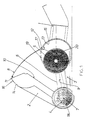
- Tuyère active d'aspirateur, se composant d'un boîtier en deux parties muni d'un raccord (1) du tuyau d'aspiration, boîtier dans lequel sont disposés un tambour-brosse (4), un entraînement (5) et une transmission qui transmet le couple de rotation séparable de l'entraînement (5) au tambour-brosse, les deux parties du boîtier étant reliées entre elles de façon détachable de sorte que l'espace intérieur du boîtier est accessible à l'utilisateur afin d'être nettoyé, la partie supérieure (2) du boîtier obturant l'intérieur de celui-ci dans une première position verrouillable de façon déblocable et débloquant, dans une seconde position, le tambour-brosse (4), la transmission (6) et l'entraînement (5), caractérisée en ce que la partie supérieure (2) du boîtier est articulée de façon pivotante à la partie inférieure (3) du boîtier et en ce que, pour obtenir la première position de verrouillage et la seconde position de déverrouillage, un mouvement de pivotement du raccord (1) du tuyau d'aspiration est réalisable.
- Tuyère d'aspirateur selon la revendication 1, caractérisée en ce que le raccord (1) du tuyau d'aspiration est articulé à la partie inférieure (3) du boîtier entre la première position qui verrouille la partie supérieure (2) du boîtier et la seconde position qui déverrouille la partie supérieure (2) du boîtier, la position de déverrouillage se trouvant dans une zone d'angle de pivotement qui se situe en dehors de la zone d'angle de pivotement du raccord du tuyau d'aspiration (1), zone nécessaire pour le mode de fonctionnement, conforme à la détermination, de la tuyère.
- Tuyère d'aspirateur selon la revendication 2, caractérisée par une butée d'arrêt (16, 17) franchissable par déformation, entre la zone d'angle de pivotement du raccord (1) du tuyau d'aspiration, zone nécessaire au mode de fonctionnement, conformément à la détermination, et la zone d'angle de pivotement qui déverrouille la partie supérieure (2) du boîtier.
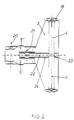
- Tuyère d'aspirateur selon l'une des revendications 2 ou 3, caractérisée en ce que la partie du raccord (1) du tuyau d'aspiration située du côté du boîtier et se présentant sous la forme d'un palier pivotant (13) est conçue en tant que partie d'un boîtier de commande destiné à l'entraînement (5) du tambourbrosse (4) de façon à empiéter au moins partiellement (14, 15) sur l'entraînement dans la zone d'angle de pivotement du mode de fonctionnement et à débloquer l'entraînement (5) dans la zone d'angle de pivotement déverrouillante.
- Tuyère d'aspirateur selon l'une des revendications 1 à 4, caractérisée par une turbine faisant fonction d'entraînement (5) pour le tambour-brosse (4).
- Tuyère d'aspirateur selon les revendications 4 et 5, caractérisée en ce que le palier (13) du raccord (1) du tuyau d'aspiration, palier situé du côté du boîtier, est conçu en tant que pièce du cylindre de turbine.
- Tuyère d'aspirateur selon l'une des revendications 1 à 6, caractérisée par une paire de poulies arrière (19) situées du côté du raccord du tuyau d'aspiration et par une paire de poulies avant (20), les axes de rotation (7) des poulies avant (18), du tambour-brosse (4) et l'axe de pivotement de la partie supérieure (2) du boîtier étant disposés de façon coaxiale les uns par rapport aux autres.
- Tuyère d'aspirateur selon l'une des revendications 1 à 7, caractérisée en ce que la transmission est une commande à courroie dentée (6) qui est accouplée, de façon centrale et du côté de l'entraînement, entre deux roues de turbine (5', 5'') tournant sur un arbre et, de façon centrale et du côté sortie, sur le tambour-brosse (4).
- Tuyère d'aspirateur selon la revendication 8, caractérisée par un carter de protection des transmissions (24) blindant entièrement l'ensemble de la commande à courroie (6, 22) lorsque le boitier de la tuyère d'aspiration (2, 3) est fermé, et conçu en deux parties dans la partie inférieure (3) et la partie supérieure (2) du boîtier de la tuyère d'aspiration, carter de protection des transmissions qui participe à l'ouverture de la commande à courroie, en la débloquant également entièrement, lors de l'ouverture de la partie supérieure du boîtier de la tuyère d'aspiration.
- Tuyère d'aspirateur selon l'une des revendication 1 à 9, caractérisée en ce que le palier pivotant de la partie supérieure du boîtier de la tuyère est pourvu d'un pivot (25) du genre d'un glisseur et d'une combinaison ouverte d'un trou rond, d'un trou oblong et d'un trou de palier (26, 27) de cette facon qu'à l'extremité ouvrante de la zone d'angle de pivotement la partie supérieure (2) du boîtier est librement retirable de la partie inférieure (3) du boîtier.
Applications Claiming Priority (2)
| Application Number | Priority Date | Filing Date | Title |
|---|---|---|---|
| DE4121130A DE4121130A1 (de) | 1991-06-26 | 1991-06-26 | Aktive staubsaugerduese |
| DE4121130 | 1991-06-26 |
Publications (2)
| Publication Number | Publication Date |
|---|---|
| EP0520175A1 EP0520175A1 (fr) | 1992-12-30 |
| EP0520175B1 true EP0520175B1 (fr) | 1995-10-11 |
Family
ID=6434799
Family Applications (1)
| Application Number | Title | Priority Date | Filing Date |
|---|---|---|---|
| EP92108007A Expired - Lifetime EP0520175B1 (fr) | 1991-06-26 | 1992-05-12 | Buse avec dispositif auxiliaire pour aspirateur |
Country Status (3)
| Country | Link |
|---|---|
| EP (1) | EP0520175B1 (fr) |
| AT (1) | ATE128832T1 (fr) |
| DE (2) | DE4121130A1 (fr) |
Families Citing this family (4)
| Publication number | Priority date | Publication date | Assignee | Title |
|---|---|---|---|---|
| US5537710A (en) * | 1993-11-02 | 1996-07-23 | Rexair, Inc. | Cleaning tool having split manifold |
| DE19517700A1 (de) * | 1995-05-13 | 1996-11-14 | Vorwerk Co Interholding | Aufnahmevorrichtung für eine oder mit einer Bürste für ein Bodenreinigungsgerät |
| US6513190B1 (en) | 2000-04-21 | 2003-02-04 | The Hoover Company | Turbine powered vacuum cleaner nozzle |
| US10448798B2 (en) | 2015-12-10 | 2019-10-22 | Jiangsu Midea Cleaning Appliances Co., Ltd. | Floor brush assembly for upright vacuum cleaner and upright vacuum cleaner with the same |
Family Cites Families (4)
| Publication number | Priority date | Publication date | Assignee | Title |
|---|---|---|---|---|
| DE1243346B (de) * | 1959-03-06 | 1967-06-29 | Preco Inc | Luftturbine fuer den Antrieb eines Reinigungswerkzeuges in einem Staubsaugermundstueck |
| US4397060A (en) * | 1981-03-26 | 1983-08-09 | Black & Decker Inc. | Vacuum cleaner tool for use on horizontal and vertical surfaces |
| DE3879867T2 (de) * | 1987-10-23 | 1993-10-14 | Matsushita Electric Ind Co Ltd | Staubsaugermundstück. |
| DE4000374A1 (de) * | 1989-01-31 | 1990-08-02 | Duepro Ag | Mehrzweck-saugduese |
-
1991
- 1991-06-26 DE DE4121130A patent/DE4121130A1/de not_active Withdrawn
-
1992
- 1992-05-12 AT AT92108007T patent/ATE128832T1/de not_active IP Right Cessation
- 1992-05-12 DE DE59203957T patent/DE59203957D1/de not_active Expired - Fee Related
- 1992-05-12 EP EP92108007A patent/EP0520175B1/fr not_active Expired - Lifetime
Also Published As
| Publication number | Publication date |
|---|---|
| EP0520175A1 (fr) | 1992-12-30 |
| DE4121130A1 (de) | 1993-01-07 |
| DE59203957D1 (de) | 1995-11-16 |
| ATE128832T1 (de) | 1995-10-15 |
Similar Documents
| Publication | Publication Date | Title |
|---|---|---|
| EP0526694B1 (fr) | Buse avec dispositif actif pour aspirateur | |
| DE69918564T2 (de) | Konstruktion eines staubsaugermundstücks | |
| DE69936861T2 (de) | Steckverbinderanordnung für staubsaugerbeutel | |
| EP0277628B1 (fr) | Dispositif de nettoyage par succion | |
| EP0339323B1 (fr) | Aspirateur de poussières électrique | |
| DE69305561T2 (de) | Staubsauger | |
| DE69205179T2 (de) | Handstaubsauger. | |
| EP0289710B1 (fr) | Disposition de sacs filtrants dans des aspirateurs électriques | |
| DE709147C (de) | Staubsauger | |
| EP4054393A1 (fr) | Machine de nettoyage de sol et procédé de fonctionnement d'une machine de nettoyage de sol | |
| EP0361240B1 (fr) | Collecteur de poussières pour aspirateur | |
| EP0520175B1 (fr) | Buse avec dispositif auxiliaire pour aspirateur | |
| DE102010030731B4 (de) | Staubsaugerdüse | |
| DE69015548T2 (de) | Staubsauger. | |
| DE3414862A1 (de) | Staubsaugermundstueck mit saugrohranschluss, gleitsohle und rotierender buerstenwalze | |
| DE29901362U1 (de) | Aufnehmende Kehrmaschine | |
| DE3520119A1 (de) | Staubsaugerduese mit rotierender buerste | |
| DE19821705A1 (de) | Sauggerät zum Ansaugen von Schmutz o. dgl. enthaltendem Sauggut | |
| DE19520778C1 (de) | Saugvorrichtung für eine Kehrmaschine | |
| DE1124990B (de) | Strassenkehrmaschine | |
| WO2022048879A1 (fr) | Balayeuse automobile et procédé de production d'une balayeuse | |
| EP0441320A1 (fr) | Embout d'aspirateur avec brosse à moteur électrique | |
| DE10342455A1 (de) | Bodenreinigungsmaschine | |
| EP0064161A1 (fr) | Buse suceuse à attacher à une tuyère d'aspiration raccordée à un aspirateur de poussières | |
| DE3723148A1 (de) | Schmutzsaugerentsorgung |
Legal Events
| Date | Code | Title | Description |
|---|---|---|---|
| PUAI | Public reference made under article 153(3) epc to a published international application that has entered the european phase |
Free format text: ORIGINAL CODE: 0009012 |
|
| AK | Designated contracting states |
Kind code of ref document: A1 Designated state(s): AT DE ES FR GB IT NL SE |
|
| 17P | Request for examination filed |
Effective date: 19930624 |
|
| 17Q | First examination report despatched |
Effective date: 19940527 |
|
| GRAA | (expected) grant |
Free format text: ORIGINAL CODE: 0009210 |
|
| AK | Designated contracting states |
Kind code of ref document: B1 Designated state(s): AT DE ES FR GB IT NL SE |
|
| PG25 | Lapsed in a contracting state [announced via postgrant information from national office to epo] |
Ref country code: IT Free format text: LAPSE BECAUSE OF FAILURE TO SUBMIT A TRANSLATION OF THE DESCRIPTION OR TO PAY THE FEE WITHIN THE PRE;WARNING: LAPSES OF ITALIAN PATENTS WITH EFFECTIVE DATE BEFORE 2007 MAY HAVE OCCURRED AT ANY TIME BEFORE 2007. THE CORRECT EFFECTIVE DATE MAY BE DIFFERENT FROM THE ONE RECORDED.SCRIBED TIME-LIMIT Effective date: 19951011 Ref country code: GB Effective date: 19951011 Ref country code: ES Free format text: THE PATENT HAS BEEN ANNULLED BY A DECISION OF A NATIONAL AUTHORITY Effective date: 19951011 Ref country code: NL Free format text: LAPSE BECAUSE OF FAILURE TO SUBMIT A TRANSLATION OF THE DESCRIPTION OR TO PAY THE FEE WITHIN THE PRESCRIBED TIME-LIMIT Effective date: 19951011 Ref country code: FR Effective date: 19951011 |
|
| REF | Corresponds to: |
Ref document number: 128832 Country of ref document: AT Date of ref document: 19951015 Kind code of ref document: T |
|
| REF | Corresponds to: |
Ref document number: 59203957 Country of ref document: DE Date of ref document: 19951116 |
|
| PG25 | Lapsed in a contracting state [announced via postgrant information from national office to epo] |
Ref country code: SE Effective date: 19960111 |
|
| NLV1 | Nl: lapsed or annulled due to failure to fulfill the requirements of art. 29p and 29m of the patents act | ||
| EN | Fr: translation not filed | ||
| GBV | Gb: ep patent (uk) treated as always having been void in accordance with gb section 77(7)/1977 [no translation filed] |
Effective date: 19951011 |
|
| PG25 | Lapsed in a contracting state [announced via postgrant information from national office to epo] |
Ref country code: AT Effective date: 19960512 |
|
| PLBE | No opposition filed within time limit |
Free format text: ORIGINAL CODE: 0009261 |
|
| STAA | Information on the status of an ep patent application or granted ep patent |
Free format text: STATUS: NO OPPOSITION FILED WITHIN TIME LIMIT |
|
| 26N | No opposition filed | ||
| PGFP | Annual fee paid to national office [announced via postgrant information from national office to epo] |
Ref country code: DE Payment date: 20090630 Year of fee payment: 18 |
|
| PG25 | Lapsed in a contracting state [announced via postgrant information from national office to epo] |
Ref country code: DE Free format text: LAPSE BECAUSE OF NON-PAYMENT OF DUE FEES Effective date: 20101201 |