EP0520439A2 - Générateur électronique de courant de soudage pour le soudage à arc pulsé - Google Patents
Générateur électronique de courant de soudage pour le soudage à arc pulsé Download PDFInfo
- Publication number
- EP0520439A2 EP0520439A2 EP92110696A EP92110696A EP0520439A2 EP 0520439 A2 EP0520439 A2 EP 0520439A2 EP 92110696 A EP92110696 A EP 92110696A EP 92110696 A EP92110696 A EP 92110696A EP 0520439 A2 EP0520439 A2 EP 0520439A2
- Authority
- EP
- European Patent Office
- Prior art keywords
- pulse
- voltage
- arc
- basic
- setpoint
- Prior art date
- Legal status (The legal status is an assumption and is not a legal conclusion. Google has not performed a legal analysis and makes no representation as to the accuracy of the status listed.)
- Withdrawn
Links
Images
Classifications
-
- B—PERFORMING OPERATIONS; TRANSPORTING
- B23—MACHINE TOOLS; METAL-WORKING NOT OTHERWISE PROVIDED FOR
- B23K—SOLDERING OR UNSOLDERING; WELDING; CLADDING OR PLATING BY SOLDERING OR WELDING; CUTTING BY APPLYING HEAT LOCALLY, e.g. FLAME CUTTING; WORKING BY LASER BEAM
- B23K9/00—Arc welding or cutting
- B23K9/09—Arrangements or circuits for arc welding with pulsed current or voltage
- B23K9/091—Arrangements or circuits for arc welding with pulsed current or voltage characterised by the circuits
Definitions
- the invention relates to an electronic welding current generator according to the preamble of claim 1.
- the real arc voltage cannot be directly recorded as actual value for the purpose of regulating the pulse voltage, since electrical tapping is not possible on the arc. In most cases, the actual voltage value is therefore tapped at the output terminals of the welding power source.
- the setpoint value Up of the pulse voltage is set taking into account the other relevant parameters until the welding process runs optimally.
- the effective arc voltage is less than the regulated generator output voltage. The difference results from the voltage drop at the welding cables and the voltage drop at the contact nozzle.
- the invention has for its object to immediately recognize and effectively suppress or regulate to a set length in an electronic welding current generator of the type mentioned tendencies to shorten or extend the arc.
- the invention has the salient advantage that the arc length control in pulsed arc welding increases the process stability in both directions, the contact nozzle consumption is considerably reduced and the downtimes are reduced. In a practical test arrangement, the contact nozzle service life could be increased to 5 times the welding cycles when using the invention.
- the arc length also remains stable during manual welding, such as swinging in a fillet weld; in addition, the frequency of spatter is greatly reduced. Furthermore, the influence of the increase in welding cable resistance is Heating of the welding cables now has no influence on the welding process.
- the essence of the invention lies in the acquisition of a measured value which is directly proportional to the actual arc length, the principle of pulse technology with Up-I G modulation being advantageously used.
- the pulse voltage Up is regulated during the pulse phase tp, while the basic current I G is regulated during the basic phase t G. If the generator voltage is measured time-selectively during the basic phase t G , stored and updated after each pulse period, a measurement value proportional to the arc length is obtained in this way, which is excellently available for a higher-level control system that maintains the arc length.
- U IG master voltage for the base current I G This advantageously allows a characteristic curve that takes into account all process influences, which can be obtained similar to the rigid VDE characteristic curve.
- the process parameters required in pulse technology such as setpoints Up, tp or t G , can be incrementally or decrementally intervened, the degree of intervention, the control factor, being adjustable or rigidly defined.
- This Up-t G control type is particularly suitable for manual welding.
- one of the three aforementioned control types can be specified or switched on.
- the prerequisite for this is an optimally set welding process, whereby an existing control switch must be in the adjustment position.
- a differential display of any type can be switched, for example on a zero point instrument or LED line display, etc., in order to detect positive and negative deviations from zero
- the PI controller only acts as a P controller with a defined gain and thus functions as a display amplifier.
- This adjustment can also be carried out automatically be designed (automatic zero point adjustment).
- the control manipulated variable ⁇ Y can be assigned a limit indicator that signals to the user when the increased service life has been reached.
- the limit value detector preferably receives the arithmetic mean value of the manipulated variable as an input variable, thereby suppressing rapid manipulated variable fluctuations.
- the limit value detector is preferably blocked in the adjustment position and during the ignition phase of a welding process in order to avoid false messages; it is thus released with a delay.
- the limit value can be set with an assigned potentiometer for setting the limit value voltage U Gw .
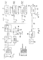
- a period T of the welding voltage 1 is shown in the block diagram in FIG. 1 of the electronic welding current generator.
- a higher generator pulse voltage Up is generated during the pulse phases tp and a lower generator basic voltage U G is generated during the basic phases t G , the basic phases t G preferably taking longer than the pulse phases tp.
- the welding voltage signal is given to an adaptation network 2, if necessary for adaptation of the measured value and / or for standardization and possibly for electrical isolation.
- the output signal of the network 2 is fed to a sample-and-hold circuit 3 for time-selective detection of the straight branch of the basic voltage U G of the welding voltage signal; at the same time, the output signal from the network 2 is applied in parallel to a module 4 for the selection and determination of the basic phase t G.
- This module 4 is used to delay the sample signal when the measuring voltage drops, but to switch it off immediately when the measuring voltage increases, so that actually only the horizontal branch of the basic voltage U G is detected.
- This measured value E obtained in this way is directly proportional to the real length LL of the arc.
- the measured value E is updated by each period T of the welding voltage, so that an updated measured value E proportional to the arc length LL is always available at the output of the sample-and-hold circuit 3; this measured value E thus represents the actual value of the basic voltage U G , which is directly proportional to the arc length LL that actually acts.
- the target value SWU LL is obtained from a block 6 of the comparison of this measured value E (actual value U G) is carried out with an adjustable set value for the arc length SWLL, which is preferably a voltage value SWU LL.
- the basic voltage U o is set via a potentiometer 19 of the module 6. In this way, the control deviation ⁇ X is obtained at the input of the PI controller 5, which is fed to the PI controller 5.
- a characteristic curve taking into account all process influences can be set, similar to the rigid VDE characteristic curve.
- the control deviation ⁇ X w is amplified by the PI controller 5 to the manipulated variable ⁇ Y, which represents the control output variable.
- the process parameters required in pulse technology such as setpoints, pulse voltage Up, pulse phase tp or basic phase t G, can now be incrementally or decrementally intervened.
- the degree of intervention, that is the control factor a can be designed to be adjustable or rigid.
- the manipulated variable ⁇ Y is given in parallel through a diode 7 in the forward direction to a switch 9 for the control mode "pulse voltage increase with tendency to arc shortening", i.e. If the arc length decreases, the pulse voltage is increased until the original arc length is reached again with this type of control.
- This type of control optimizes the welding process in particular.
- the manipulated variable ⁇ Y is applied via a diode 7 ', which is polarized in the forward direction, to a switch 9' for the control type "pulse voltage increase and pulse time increase with a tendency to shorten the arc", i.e. If the arc length decreases, the pulse voltage and the pulse width are increased until the original arc length is reached again.
- the manipulated variable ⁇ Y is applied to a switch 9 "via a diode 8 switched in the reverse direction in order to generate the control type" pulse voltage increase with a tendency to shorten the arc and increase in the base time with a tendency to extend the arc ", ie the control type serves to increase the pulse voltage when the arc length decreases and to increase the base time when the arc length increases Arc voltage and is mainly used for manual welding.
- a potentiometer 10, 10', 10" is arranged in front of each module 11, 11 ', 11 "in order to control factor a or a1 or
- SWU t p U t p + dU t p for module 11 'or
- SWU tG U tG + dU tG for module 11 ".
- This setpoint can now be used as a control variable in a suitable power unit used will.
- the manipulated variable ⁇ Y is equally given, preferably via an RC network 15, for averaging, a limit indicator 12 and, in parallel, a module 16 for display adaptation, the output signal of which is given to a display instrument 17 which is capable of displaying a ⁇ zero deviation.
- the limit indicator 12 signals to the user when the increased service life has been reached due to the higher-level control of the control types mentioned.
- the arithmetic averaging of the manipulated variable suppresses rapid manipulated variable swings.
- the limit indicator 12 is blocked by means of a switch 14 in the adjustment position and during the ignition phase of a welding process in order to avoid incorrect messages; it is released with a delay.
- the limit value voltage U Gw can be specified to the limit value detector 12 via a potentiometer 13.
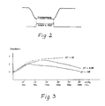
- FIG. 2 shows the acquisition of the basic voltage by the sample-and-hold circuit 3.
- the sample-and-hold signal is only applied to the measuring voltage during the basic phase t G when the basic voltage U G has actually been reached, ie that in this way only the horizontal branch of the measuring voltage is detected.
- the basic voltage is stored and is available in the hold phase as a preferably positive actual value signal for the subsequent setpoint / actual value comparison.
- the setpoint / actual value comparison takes place at the input of the PI controller 5, whose PI behavior can be predetermined in a changeable manner.
- Figure 3 shows the relationship between the control factor and the basic phase t G and the control voltage U tG . It can be seen that at short t G times the controller intervention is weakened because the so-called "internal control" is more effective, ie the tp phase is relatively large compared to the period duration T. At long t G times, From around 15 ms, the controller intervention becomes degressive so that the pulse frequency does not become too low.
Landscapes
- Engineering & Computer Science (AREA)
- Physics & Mathematics (AREA)
- Plasma & Fusion (AREA)
- Mechanical Engineering (AREA)
- Arc Welding Control (AREA)
- Generation Of Surge Voltage And Current (AREA)
Applications Claiming Priority (2)
| Application Number | Priority Date | Filing Date | Title |
|---|---|---|---|
| DE4121237A DE4121237C2 (de) | 1991-06-27 | 1991-06-27 | Elektronischer Schweißstrom-Generator für das Impuls-Lichtbogenschweißen |
| DE4121237 | 1991-06-27 |
Publications (2)
| Publication Number | Publication Date |
|---|---|
| EP0520439A2 true EP0520439A2 (fr) | 1992-12-30 |
| EP0520439A3 EP0520439A3 (en) | 1994-11-09 |
Family
ID=6434867
Family Applications (1)
| Application Number | Title | Priority Date | Filing Date |
|---|---|---|---|
| EP9292110696A Withdrawn EP0520439A3 (en) | 1991-06-27 | 1992-06-25 | Electronic welding current generator for pulsed-arc welding |
Country Status (5)
| Country | Link |
|---|---|
| US (1) | US5293027A (fr) |
| EP (1) | EP0520439A3 (fr) |
| JP (1) | JPH06155025A (fr) |
| CA (1) | CA2072711A1 (fr) |
| DE (1) | DE4121237C2 (fr) |
Cited By (1)
| Publication number | Priority date | Publication date | Assignee | Title |
|---|---|---|---|---|
| US6307177B1 (en) | 1997-04-25 | 2001-10-23 | Kuka Schweissanlagen Gmbh | Method and device for determining the voltage at welding power sources |
Families Citing this family (33)
| Publication number | Priority date | Publication date | Assignee | Title |
|---|---|---|---|---|
| US5756966A (en) * | 1995-09-22 | 1998-05-26 | General Electric Company | Method for joining metal components with improved arc voltage sensing and control |
| TW445192B (en) | 1999-04-12 | 2001-07-11 | Tri Tool Inc | Control method and apparatus for an arc welding system |
| DE10033387C2 (de) * | 2000-07-08 | 2002-11-07 | Nimak Lichtbogenschweismaschin | Verfahren und Gerät zum Schweißen oder Löten von Metall mittels Impulslichtbogen |
| US10040143B2 (en) | 2012-12-12 | 2018-08-07 | Illinois Tool Works Inc. | Dabbing pulsed welding system and method |
| US10906114B2 (en) | 2012-12-21 | 2021-02-02 | Illinois Tool Works Inc. | System for arc welding with enhanced metal deposition |
| US9950383B2 (en) | 2013-02-05 | 2018-04-24 | Illinois Tool Works Inc. | Welding wire preheating system and method |
| US10835983B2 (en) | 2013-03-14 | 2020-11-17 | Illinois Tool Works Inc. | Electrode negative pulse welding system and method |
| US11045891B2 (en) | 2013-06-13 | 2021-06-29 | Illinois Tool Works Inc. | Systems and methods for anomalous cathode event control |
| US10828728B2 (en) | 2013-09-26 | 2020-11-10 | Illinois Tool Works Inc. | Hotwire deposition material processing system and method |
| US9539662B2 (en) | 2013-10-30 | 2017-01-10 | Illinois Tool Works Inc. | Extraction of arc length from voltage and current feedback |
| US11154946B2 (en) | 2014-06-30 | 2021-10-26 | Illinois Tool Works Inc. | Systems and methods for the control of welding parameters |
| US11198189B2 (en) | 2014-09-17 | 2021-12-14 | Illinois Tool Works Inc. | Electrode negative pulse welding system and method |
| US11478870B2 (en) | 2014-11-26 | 2022-10-25 | Illinois Tool Works Inc. | Dabbing pulsed welding system and method |
| US10189106B2 (en) | 2014-12-11 | 2019-01-29 | Illinois Tool Works Inc. | Reduced energy welding system and method |
| US11370050B2 (en) | 2015-03-31 | 2022-06-28 | Illinois Tool Works Inc. | Controlled short circuit welding system and method |
| US11285559B2 (en) | 2015-11-30 | 2022-03-29 | Illinois Tool Works Inc. | Welding system and method for shielded welding wires |
| US10610946B2 (en) | 2015-12-07 | 2020-04-07 | Illinois Tool Works, Inc. | Systems and methods for automated root pass welding |
| US12194579B2 (en) | 2015-12-10 | 2025-01-14 | Illinois Tool Works Inc. | Systems, methods, and apparatus to preheat welding wire |
| US10675699B2 (en) | 2015-12-10 | 2020-06-09 | Illinois Tool Works Inc. | Systems, methods, and apparatus to preheat welding wire |
| US10766092B2 (en) | 2017-04-18 | 2020-09-08 | Illinois Tool Works Inc. | Systems, methods, and apparatus to provide preheat voltage feedback loss protection |
| US10870164B2 (en) | 2017-05-16 | 2020-12-22 | Illinois Tool Works Inc. | Systems, methods, and apparatus to preheat welding wire |
| CA3066666C (fr) | 2017-06-09 | 2024-10-01 | Illinois Tool Works Inc. | Pointes de contact dotees de filets et d'une tete pour permettre le devissage ou filets comprenant des fentes longitudinales destinees a un ecoulement de gaz; chalumeau de soudagedote de pointes de contact |
| EP3634684B1 (fr) | 2017-06-09 | 2022-10-05 | Illinois Tool Works Inc. | Chalumeau de soudage doté d'une première pointe de contact pour préchauffer un fil de soudage et d'une seconde pointe de contact |
| US11524354B2 (en) | 2017-06-09 | 2022-12-13 | Illinois Tool Works Inc. | Systems, methods, and apparatus to control weld current in a preheating system |
| US11247290B2 (en) | 2017-06-09 | 2022-02-15 | Illinois Tool Works Inc. | Systems, methods, and apparatus to preheat welding wire |
| CA3066677C (fr) | 2017-06-09 | 2023-04-04 | Illinois Tool Works Inc. | Ensemble de soudage pour un chalumeau de soudage, avec deux pointes de contact et un corps de refroidissement pour refroidir et conduire un courant |
| US11020813B2 (en) | 2017-09-13 | 2021-06-01 | Illinois Tool Works Inc. | Systems, methods, and apparatus to reduce cast in a welding wire |
| EP3843933B1 (fr) | 2018-08-31 | 2026-01-14 | Illinois Tool Works, Inc. | Système de soudage à l'arc submergé et chalumeau de soudage à l'arc submergé pour le préchauffage résistif d'un fil d'électrode |
| US11014185B2 (en) | 2018-09-27 | 2021-05-25 | Illinois Tool Works Inc. | Systems, methods, and apparatus for control of wire preheating in welding-type systems |
| EP3898055A2 (fr) | 2018-12-19 | 2021-10-27 | Illinois Tool Works, Inc. | Systèmes, procédés et appareil pour préchauffer un fil de soudage |
| US12583048B2 (en) | 2019-03-29 | 2026-03-24 | Illinois Tool Works Inc. | Methods and apparatus to convert welding-type power to welding-type power and resistive preheating power |
| US12103121B2 (en) | 2019-04-30 | 2024-10-01 | Illinois Tool Works Inc. | Methods and apparatus to control welding power and preheating power |
| US11772182B2 (en) | 2019-12-20 | 2023-10-03 | Illinois Tool Works Inc. | Systems and methods for gas control during welding wire pretreatments |
Family Cites Families (9)
| Publication number | Priority date | Publication date | Assignee | Title |
|---|---|---|---|---|
| CH629134A5 (de) * | 1977-09-19 | 1982-04-15 | Oerlikon Buehrle Schweisstech | Vorrichtung zum mig-impulslichtbogenschweissen. |
| JPS5719185A (en) * | 1980-07-08 | 1982-02-01 | Mitsubishi Electric Corp | Pulse arc welding device |
| US4409465A (en) * | 1981-04-24 | 1983-10-11 | Osaka Transformer Co., Ltd. | Pulse arc welding method and device in which pulse current and background current have a constant current characteristic |
| CA1187562A (fr) * | 1982-08-31 | 1985-05-21 | Edward Shmakov | Dispositif et methode de soudage |
| US4529864A (en) * | 1983-05-23 | 1985-07-16 | Bennett Dale E | Closed loop control apparatus for short-circuit arc welding |
| US4647754A (en) * | 1984-04-10 | 1987-03-03 | Matsushita Electric Industrial Co., Ltd. | Consumable electrode type pulse arc welding machine |
| ATE95741T1 (de) * | 1986-06-04 | 1993-10-15 | Welding Ind Of Australia | Impulslichtbogenschweissen. |
| US4794232A (en) * | 1986-09-17 | 1988-12-27 | Kinetic Energy Corporation | Control for gas metal arc welding system |
| SE8900758A0 (sv) * | 1989-03-06 | 1990-09-07 | Esab Ab | Sätt vid pulsbågsvetsning |
-
1991
- 1991-06-27 DE DE4121237A patent/DE4121237C2/de not_active Expired - Fee Related
-
1992
- 1992-06-25 EP EP9292110696A patent/EP0520439A3/de not_active Withdrawn
- 1992-06-29 JP JP4171278A patent/JPH06155025A/ja active Pending
- 1992-06-29 US US07/905,825 patent/US5293027A/en not_active Expired - Fee Related
- 1992-06-29 CA CA002072711A patent/CA2072711A1/fr not_active Abandoned
Cited By (1)
| Publication number | Priority date | Publication date | Assignee | Title |
|---|---|---|---|---|
| US6307177B1 (en) | 1997-04-25 | 2001-10-23 | Kuka Schweissanlagen Gmbh | Method and device for determining the voltage at welding power sources |
Also Published As
| Publication number | Publication date |
|---|---|
| JPH06155025A (ja) | 1994-06-03 |
| CA2072711A1 (fr) | 1992-12-28 |
| DE4121237C2 (de) | 1994-07-21 |
| EP0520439A3 (en) | 1994-11-09 |
| US5293027A (en) | 1994-03-08 |
| DE4121237A1 (de) | 1993-01-07 |
Similar Documents
| Publication | Publication Date | Title |
|---|---|---|
| EP0520439A2 (fr) | Générateur électronique de courant de soudage pour le soudage à arc pulsé | |
| EP2495496B1 (fr) | Installation de brûleur | |
| DE3134002C2 (de) | Vorrichtung zur Steuerung der Drehzahl eines Induktionsmotors | |
| DE3407067A1 (de) | Steuerschaltung fuer gasentladungslampen | |
| DE2422844C3 (de) | Röntgendiagnostikapparat, bei dem die Röntgenröhrenspannung über den Röntgenröhrenheizstrom geregelt wird | |
| DE3407066A1 (de) | Verfahren zum zuschalten von lampengruppen eines gasentladungslampen-beleuchtungssystems sowie beleuchtungssystem zum durchfuehren des verfahrens | |
| DE2728563A1 (de) | Roentgendiagnostikgenerator mit einem seinen hochspannungstransformator speisenden wechselrichter | |
| DE3325992A1 (de) | Schutzschaltung gegen kurzschluss der erregerwicklung fuer einen niederspannungssynchrongenerator mit einem spannungsregler, insbesondere zum einsatz bei kraftfahrzeugen | |
| DE69120930T2 (de) | Vorrichtung zum Schmelzverbinden von optischen Fasern | |
| EP3767174A1 (fr) | Procédé et dispositif d'étalonnage ultérieur d'un système de mesure permettant de réguler un mélange gaz-air de combustion dans un appareil de chauffage | |
| DE3932399C1 (en) | Operating series length regulating loop - switching in adjuster again during delay time if current falls again below threshold value | |
| DE2726890A1 (de) | Speise- und regelschaltung fuer eine gasgefuellte neutronenroehre und verfahren zum speisen und regeln der neutronenroehre | |
| EP0427879A1 (fr) | Appareil et procédé de chauffage par induction de pièces | |
| DE1538609C3 (de) | Transistorisierte Schaltungsanordnung zum automatischen Prüfen gedruckter Leitungszüge | |
| EP1094592B1 (fr) | Procédé de limitation de tension de sortie pour un convertisseur commandé en tension/fréquence avec circuit intermédiaire et un convertisseur | |
| DE3618025A1 (de) | Vorrichtung zur bestimmung der regelguete und der stabilitaet von regelkreisen aus messwerten und kennwerten des regelkreises | |
| EP0590181A1 (fr) | Méthode de détermination du temps de fermeture d'un circuit primaire d'un système d'allumage d'un moteur à combustion interne | |
| DE4121740A1 (de) | Lichtbogenschweissmaschine mit ferneinsteller | |
| DE3439115A1 (de) | Drucker | |
| DE4322597C2 (de) | Anordnung zur hochauflösenden Analog/Digital-Wandlung von Signalen mit unterschiedlichen Signalamplituden | |
| DE4040008C2 (de) | Verfahren und Vorrichtung zum Lichtbogenschweißen von metallischen Objekten | |
| DE4318502C1 (de) | Verfahren und Schaltung zur Überwachung der Ströme von Leistungskondensatoren zur Blindleistungskompensation | |
| DE2940087C2 (de) | Prüfvorrichtung zum Prüfen eines Reglers | |
| DE958041C (de) | Wechselstromgesteuerte Relaisanordnung | |
| DE1563633C3 (de) | Stromversorgungsschaltung |
Legal Events
| Date | Code | Title | Description |
|---|---|---|---|
| PUAI | Public reference made under article 153(3) epc to a published international application that has entered the european phase |
Free format text: ORIGINAL CODE: 0009012 |
|
| AK | Designated contracting states |
Kind code of ref document: A2 Designated state(s): AT BE CH DE DK ES FR GB GR IT LI LU MC NL PT SE |
|
| PUAL | Search report despatched |
Free format text: ORIGINAL CODE: 0009013 |
|
| AK | Designated contracting states |
Kind code of ref document: A3 Designated state(s): AT BE CH DE DK ES FR GB GR IT LI LU MC NL PT SE |
|
| STAA | Information on the status of an ep patent application or granted ep patent |
Free format text: STATUS: THE APPLICATION IS DEEMED TO BE WITHDRAWN |
|
| 18D | Application deemed to be withdrawn |
Effective date: 19950510 |