EP0520531A1 - Verfahren zur adaptiven Drucksteuerung bei einem automatischen Schaltgetriebe - Google Patents
Verfahren zur adaptiven Drucksteuerung bei einem automatischen Schaltgetriebe Download PDFInfo
- Publication number
- EP0520531A1 EP0520531A1 EP92201502A EP92201502A EP0520531A1 EP 0520531 A1 EP0520531 A1 EP 0520531A1 EP 92201502 A EP92201502 A EP 92201502A EP 92201502 A EP92201502 A EP 92201502A EP 0520531 A1 EP0520531 A1 EP 0520531A1
- Authority
- EP
- European Patent Office
- Prior art keywords
- pressure
- actuator
- variability
- correction
- adaptive
- Prior art date
- Legal status (The legal status is an assumption and is not a legal conclusion. Google has not performed a legal analysis and makes no representation as to the accuracy of the status listed.)
- Withdrawn
Links
Images


Classifications
-
- F—MECHANICAL ENGINEERING; LIGHTING; HEATING; WEAPONS; BLASTING
- F16—ENGINEERING ELEMENTS AND UNITS; GENERAL MEASURES FOR PRODUCING AND MAINTAINING EFFECTIVE FUNCTIONING OF MACHINES OR INSTALLATIONS; THERMAL INSULATION IN GENERAL
- F16H—GEARING
- F16H61/00—Control functions within control units of change-speed- or reversing-gearings for conveying rotary motion ; Control of exclusively fluid gearing, friction gearing, gearings with endless flexible members or other particular types of gearing
- F16H61/04—Smoothing ratio shift
- F16H61/06—Smoothing ratio shift by controlling rate of change of fluid pressure
- F16H61/061—Smoothing ratio shift by controlling rate of change of fluid pressure using electric control means
-
- F—MECHANICAL ENGINEERING; LIGHTING; HEATING; WEAPONS; BLASTING
- F16—ENGINEERING ELEMENTS AND UNITS; GENERAL MEASURES FOR PRODUCING AND MAINTAINING EFFECTIVE FUNCTIONING OF MACHINES OR INSTALLATIONS; THERMAL INSULATION IN GENERAL
- F16H—GEARING
- F16H61/00—Control functions within control units of change-speed- or reversing-gearings for conveying rotary motion ; Control of exclusively fluid gearing, friction gearing, gearings with endless flexible members or other particular types of gearing
- F16H2061/0075—Control functions within control units of change-speed- or reversing-gearings for conveying rotary motion ; Control of exclusively fluid gearing, friction gearing, gearings with endless flexible members or other particular types of gearing characterised by a particular control method
- F16H2061/0087—Adaptive control, e.g. the control parameters adapted by learning
-
- F—MECHANICAL ENGINEERING; LIGHTING; HEATING; WEAPONS; BLASTING
- F16—ENGINEERING ELEMENTS AND UNITS; GENERAL MEASURES FOR PRODUCING AND MAINTAINING EFFECTIVE FUNCTIONING OF MACHINES OR INSTALLATIONS; THERMAL INSULATION IN GENERAL
- F16H—GEARING
- F16H61/00—Control functions within control units of change-speed- or reversing-gearings for conveying rotary motion ; Control of exclusively fluid gearing, friction gearing, gearings with endless flexible members or other particular types of gearing
- F16H61/68—Control functions within control units of change-speed- or reversing-gearings for conveying rotary motion ; Control of exclusively fluid gearing, friction gearing, gearings with endless flexible members or other particular types of gearing specially adapted for stepped gearings
- F16H61/684—Control functions within control units of change-speed- or reversing-gearings for conveying rotary motion ; Control of exclusively fluid gearing, friction gearing, gearings with endless flexible members or other particular types of gearing specially adapted for stepped gearings without interruption of drive
Definitions
- This invention relates to an adaptive pressure control method for an automatic transmission, and more particularly, to a control method for characterizing the source of the adaptive error.
- Shifting between speed ratios in an automatic transmission involves an exchange of on-coming and off-going fluid operated friction elements (clutches/torque establishing devices) and is generally characterized as comprising three successive phases: a fill phase, a torque phase and an inertia phase.
- the fill phase the on-coming friction element is prepared for torque transmission; in the torque phase, the torque exchange occurs without a corresponding speed change; and in the inertia phase, the speed change occurs.
- the fluid pressure supplied to the on-coming friction element during the torque and inertia phases is progressively increased in accordance with a predetermined pressure schedule.
- the scheduled pressure is used to generate an electrical drive signal, typically in the form of a PWM duty cycle, which is applied to an (electro-hydraulic) actuator.
- the actuator is connected to a source of fluid pressure and operates to develop a fluid apply pressure therefrom in relation to the drive signal.
- the scheduled pressure values are calibrated to achieve optimum shift quality in a nominal vehicle, but actuator variability and clutch performance variations which occur over time may adversely affect the shift quality actually achieved. For this reason, adaptive control techniques have been employed to correct the predetermined pressure schedule, based on a measure of the deviation of the actual shift quality from the desired or optimum shift quality.
- An example of such a control is set forth in US Patent No. 4,653,350.
- the adaptive pressure corrections are developed under specified intermediate pressure range operating conditions known to provide accurate, repeatable results, and then applied to other operating conditions by extrapolation. This produces beneficial results under most operating conditions, but tends to overpressure or underpressure the torque establishing devices under certain operating conditions due to the nonlinearity of the actuator error. Specifically, relatively little error occurs at the limits of operation (that is, 0% and 100% duty cycle), but considerable deviation may occur at intermediate duty cycle values. This phenomenon is graphically illustrated by the pressure vs. duty cycle traces 610 and 612 of Figure 2, where trace 610 represents the idealized output pressure of the actuator over the range of PWM duty cycles, and trace 612 represents the actual relationship. Thus, it can be assumed that little or no actuator variability will occur in a shift performed at or near the limits of the duty cycle range.
- a method in accordance with the present invention is characterised by the features specified in the characterising portion of claim 1.
- the present invention is directed to an improved adaptive pressure control method for an automatic transmission in which the fluid pressure developed by an (electro-hydraulic) actuator is directed to a plurality of (fluid operated) torque establishing devices, wherein adaptive pressure corrections occasioned by actuator variability do not impair shift quality in operating regions known to be substantially free of actuator variability.
- the control method of this invention is carried out by providing separate adaptive correction amounts for each torque establishing device, comparing the adaptive correction amounts to determine the component, if any, occasioned by actuator variability, and utilizing such component to a degree which depends on the scheduled pressure.
- An underlying assumption is that actuator variability will be manifested in the adaptive corrections for each of the torque establishing devices.
- the correction amount common to all of the torque establishing devices is primarily due to actuator variability.
- LPCA Line Pressure Characterization Adaptive
- the adaptive pressure correction amounts are used to advantage in the intermediate pressure range of the actuator by compensating for the combined variability of the actuator and torque establishing devices, without overpressuring the torque establishing devices in operating regions where the actuator variability is substantially negligible. This improves the shift quality of the automatic transmission and increases the tolerance of the system to actuator variability.
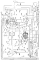
- the reference numeral 10 generally designates a motor vehicle drivetrain including an engine 12 and a (parallel shaft) automatic transmission 14 having a reverse speed ratio and four forward speed ratios.
- Engine 12 includes a throttle mechanism 16 mechanically connected to an operator manipulated device, such as an accelerator pedal (not shown) for regulating engine output torque, such torque being applied to the automatic transmission 14 through the engine output shaft 18.
- the automatic transmission 14 transmits engine output torque to a pair of drive axles 20, 22 through a torque converter 24 and one or more (fluid operated) clutches 26 - 34, such clutches being applied or released according to a predetermined schedule for establishing the desired transmission speed ratio, and defining torque establishing devices.
- Impeller or input member 36 of the torque converter 24 is connected to be rotatably driven by the output shaft 18 of engine 12 through an input shell 38.
- Turbine or output member 40 of the torque converter 24 is rotatably driven by the impeller 36 by means of fluid transfer therebetween and is connected to rotatably drive a transmission shaft 42.
- a stator member 44 redirects the fluid which couples the impeller 36 to the turbine 40, the stator member being connected through a one-way device 46 to the housing of automatic transmission 14.
- the torque converter 24 also includes the clutch 26 comprising a clutch plate 50 secured to the transmission shaft 42.
- the clutch plate 50 has a friction surface 52 formed thereon adaptable to be engaged with the inner surface of the input shell 38 to form a direct mechanical drive between the engine output shaft 18 and the transmission shaft 42.
- the clutch plate 50 divides the space between input shell 38 and the turbine 40 into two fluid chambers: an apply chamber 54 and a release chamber 56.
- a (positive displacement hydraulic) pump 60 is mechanically driven by the engine output shaft 18 through the input shell 38 and impeller 36, as indicated by the broken line 62.
- Pump 60 receives hydraulic fluid at low pressure from the fluid reservoir 64 and supplies pressurized fluid to the transmission control elements via output line 66.
- a pressure regulator valve (PRV) 68 is connected to the output line 66 and serves to regulate the fluid pressure (hereinafter referred to as line pressure) in output line 66 by returning a controlled portion of the fluid therein to fluid reservoir 64 via line 70.
- line pressure fluid pressure
- pressure regulator valve 68 supplies fluid pressure for the torque converter 24 via line 74. While the pump and pressure regulator valve designs are not critical to the present invention, a representative pump is disclosed in US Patent No. 4,342,545, and a representative pressure regulator valve is disclosed in US Patent No. 4,283,970.
- the transmission shaft 42 and a further transmission shaft 90 each have a plurality of gear elements rotatably supported thereon.
- the gear elements 80 - 88 are supported on transmission shaft 42 and the gear elements 92 - 102 are supported on transmission shaft 90.
- the gear element 88 is rigidly connected to the transmission shaft 42, and the gear elements 98 and 102 are rigidly connected to the transmission shaft 90.
- Gear element 92 is connected to the transmission shaft 90 via a freewheeler or one-way device 93.
- the gear elements 80, 84, 86 and 88 are maintained in meshing engagement with the gear elements 92, 96, 98 and 100, respectively, and the gear element 82 is coupled to the gear element 94 through a reverse idler gear 103.
- the transmission shaft 90 is coupled to the drive axles 20 and 22 through gear elements 102 and 104 and a conventional differential gear set (DG) 106.
- DG differential gear set
- a dog clutch 108 is splined on the transmission shaft 90 so as to be axially slidable thereon, and serves to rigidly connect the transmission shaft 90 either to the gear element 96 (as shown) or the gear element 94.
- a forward speed relation between the gear element 84 and transmission shaft 90 is established when dog clutch 108 connects the transmission shaft 90 to gear element 96, and a reverse speed relation between the gear element 82 and transmission shaft 90 is established when the dog clutch 108 connects the transmission shaft 90 to the gear element 94.
- the clutches 28 - 34 each comprise an input member rigidly connected to a transmission shaft 42 or 90, and an output member rigidly connected to one or more gear elements such that engagement of a clutch couples the respective gear element and transmission shaft to effect a driving connection between the transmission shafts 42 and 90.
- the clutch 28 couples the transmission shaft 42 to the gear element 80; the clutch 30 couples the transmission shaft 42 to the gear elements 82 and 84; the clutch 32 couples the transmission shaft 90 to the gear element 100; and the clutch 34 couples the transmission shaft 42 to the gear element 86.
- Each of the clutches 28 - 34 is biased toward a disengaged state by a return spring (not shown).
- the circled numeral 1 represents a fluid passage for supplying pressurized fluid to the apply chamber of clutch 28; the circled numeral 2 and letter R represent a fluid passage for supplying pressurized fluid to the apply chamber of the clutch 30; the circled numeral 3 represents a fluid passage for supplying pressurized fluid to the apply chamber of the clutch 32; and the circled numeral 4 represents a fluid passage for directing pressurized fluid to the apply chamber of the clutch 34.
- the various gear elements 80 - 88 and 92 - 100 are relatively sized such that engagement of first, second, third and fourth forward speed ratios are effected by engaging the clutches 28, 30, 32 and 34, respectively, it being understood that the dog clutch 108 must be in the position depicted in Figure 1 to obtain a forward speed ratio.
- a neutral speed ratio or an effective disconnection of the drive axles 20 and 22 from the engine output shaft 18 is effected by maintaining all of the clutches 28 - 34 in a released condition.
- the speed ratios defined by the various gear element pairs are generally characterized by the ratio of the turbine speed Nt to output speed No. Representative Nt/No ratios for automatic transmission 14 are as follows: First - 2.368 Second - 1.273 Third - 0.808 Fourth - 0.585 Reverse - 1.880
- Shifting from a current forward speed ratio to a desired forward speed ratio requires that the clutch associated with the current speed ratio (off-going) be disengaged, and the clutch associated with the desired speed ratio (on-coming) be engaged.
- a shift from the first forward speed ratio to the second forward speed ratio involves disengagement of the clutch 28 and engagement of the clutch 30.
- the fluid control elements of the automatic transmission 14 include a manual valve 140, a directional servo 160 and a plurality of (electrically operated) fluid valves 180 - 190.
- the manual valve 140 operates in response to operator demand and serves, in conjunction with directional servo 160, to direct regulated line pressure to the appropriate fluid valves 182 - 188.
- the fluid valves 182 - 188 are individually controlled to direct fluid pressure to the clutches 28 - 34.
- the fluid valve 180 is controlled to direct fluid pressure from the output line 66 to the pressure regulator valve 68, and the fluid valve 190 is controlled to direct fluid pressure from the line 74 to the clutch 26 of torque converter 24.
- the directional servo 160 operates in response to the condition of the manual valve 140 and serves to properly position the dog clutch 108.
- the manual valve 140 includes a shaft 142 for receiving axial mechanical input from the operator of the motor vehicle in relation to the speed range the operator desires.
- the shaft 142 is also connected to an indicator mechanism 144 through a suitable mechanical linkage as indicated generally by the broken line 146.
- Fluid pressure from the output line 66 is applied as an input to the manual valve 140 via the line 148, and the manual valve outputs include a forward (F) output line 150 for supplying fluid pressure for engaging forward speed ratios and a reverse (R) output line 152 for supplying fluid pressure for engaging the reverse speed ratio.
- F forward
- R reverse
- the directional servo 160 is a fluid operated device and includes an output shaft 162 connected to a shift fork 164 for axially shifting the dog clutch 108 on transmission shaft 90 to selectively enable either forward or reverse speed ratios.
- the output shaft 162 is connected to a piston 166 axially movable within the servo housing 168.
- the axial position of the piston 166 within the servo housing 168 is determined according to the fluid pressures supplied to chambers 170 and 172.
- the forward output line 150 of manual valve 140 is connected via line 174 to the chamber 170 and the reverse output line 152 of manual valve 140 is connected via line 176 to the chamber 172.
- the directional servo 160 also operates as a fluid valve for enabling the reverse speed ratio.
- the directional servo 160 includes an output line 178 connected to the (electrically operated) fluid valve 186.
- the passage between line 176 and output line 178 is cut off; when the operator selects the reverse gear ratio, the passage between the line 176 and output line 178 is open.
- the (electrically operated) fluid valves 180 - 190 each receive fluid pressure at an input passage thereof from the pump 60, and are individually controlled to direct fluid pressure to the pressure regulator valve 68 or respective clutches 26 - 34.
- the fluid valve 180 receives line pressure directly from output line 66, and is controlled to direct a variable amount of such pressure to the pressure regulator valve 68, as indicated by the circled letter V.
- the fluid valve 180 and pressure regulator valve 68 define the (electro-hydraulic) actuator of the present invention.
- the fluid valves 182, 184 and 188 receive fluid pressure from the forward output line 150 of manual valve 140, and are controlled to direct variable amounts of such pressure to the clutches 34, 32 and 28, as indicated by the circled numerals 4, 3 and 1, respectively.
- the fluid valve 186 receives fluid pressure from the forward output line 150 and the output line 178, and is controlled to direct a variable amount of such pressure to the clutch 30, as indicated by the circled numeral 2 and the circled letter R.
- the fluid valve 190 receives fluid pressure from line 74 of pressure regulator valve 68, and is controlled to direct a variable amount of such pressure to the release chamber 56 of the clutch 26, as indicated by the circled numeral 6.
- the apply chamber 54 of the clutch 26 is supplied with fluid pressure from the output line 74 via the orifice 192, as indicated by the circled numeral 5.
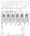
- Each of the fluid valves 180 - 190 includes a spool element 210 - 220, axially movable within the respective valve body for directing fluid flow between input and output passages.
- a respective spool element 210 - 220 When a respective spool element 210 - 220 is in the rightmost position as viewed in Figure 1, the input and output passages are connected.
- Each of the fluid valves 180 - 190 includes an exhaust passage, as indicated by the circled letters EX, such passage serving to drain fluid from the respective clutching device when the spool element is shifted to the leftmost position as viewed in Figure 1.
- each of the fluid valves 180 - 190 includes a solenoid 222 - 232 for controlling the position of its spool element 210 - 220.
- Each such solenoid 222 - 232 comprises a plunger 234 - 244 connected to the respective spool element 210 - 220 and a solenoid coil 246 - 256 surrounding the respective plunger.
- each such solenoid coil 246 - 256 is connected to ground potential as shown, and the other terminal is connected to an output line 258 - 268 of a control unit 270 which governs the solenoid coil energization.
- the control unit 270 pulse-width-modulates the solenoid coils 246 - 256 according to a predetermined control algorithm to regulate the fluid pressure supplied to the pressure regulator valve 68 and the clutches 26 - 34, the duty cycle of such modulation being determined in relation to the desired magnitude of the supplied pressures.
- fluid valves 180 - 190 have been illustrated as spool valves, other types of valves could be substituted therefor. By way of example, valves of the ball and seat type could be used. In general terms, the fluid valves 180 - 190 may be mechanized with any three-port pulse-width-modulated valving arrangement.
- Input signals for the control unit 270 are provided on the input lines 272 - 284.
- a position sensor (S) 286 responsive to movement of the manual valve shaft 142 provides an input signal to the control unit 270 via input line 272.
- Speed transducers 288, 290 and 292 sense the rotational velocity of various rotary members within the automatic transmission 14 and supply speed signals in accordance therewith to the control unit 270 via input lines 274, 276 and 278, respectively.
- the speed transducer 288 senses the velocity of the transmission shaft 42 and therefore the turbine or transmission input speed Nt;
- the speed transducer 290 senses the velocity of the drive axle 22 and therefore the transmission output speed No;
- the speed transducer 292 senses the velocity of the engine output shaft 18 and therefore the engine speed Ne.
- the position transducer 294 is responsive to the position of the throttle mechanism 16 and provides an electrical signal in accordance therewith to control unit 270 via input line 280.
- a pressure transducer 296 senses the manifold absolute pressure (MAP) of the engine 12 and provides an electrical signal to the control unit 270 in accordance therewith via input line 282.
- MAP manifold absolute pressure
- a temperature sensor 298 senses the temperature of the oil in the fluid reservoir 64 and provides an electrical signal in accordance therewith to control unit 270 via input line 284.
- the control unit 270 responds to the input signals on input lines 272 - 284 according to a predetermined control algorithm as set forth herein, for controlling the energization of the solenoid coils 246 - 256 via output lines 258 - 268.
- the control unit 270 includes an input/output (I/O) device 300 for receiving the input signals and outputting the various pulse-width-modulation signals, and a microcomputer 302 which communicates with the I/O device 300 via an address-and-control bus 304 and a bi-directional data bus 306.
- I/O input/output
- microcomputer 302 which communicates with the I/O device 300 via an address-and-control bus 304 and a bi-directional data bus 306.
- every shift from one speed ratio to another involves disengagement of an off-going clutch and engagement of an on-coming clutch.
- Each shift includes a fill phase during which the apply chamber of the on-coming clutch is filled with fluid, a torque phase during which the engine torque is transferred from the off-going clutch to the on-coming clutch, and an inertia phase during which the speed change occurs.
- the fluid pressure supplied to the on-coming clutch during the torque and inertia phases is scheduled in relation to an estimation of the gear set input torque Tv.
- the engine MAP is determined from the pressure sensor 296, while the efficiency K is stored based on previously determined data.
- the mechanical friction term tf is determined as a function of engine speed, and the load torque term TL is estimated by loading indicators.
- the torque multiplication ratio Tc is determined as a function of the speed ratio Nt/Ne.
- the desired pressure for the on-coming clutch is stored as a function of the torque variable Tv and time, as graphically depicted in Figure 3.
- the pressure vs. time schedule is defined by a pair of pressure endpoints, one such endpoint corresponding to an initial time ti, and the other corresponding to a final time tf.
- the initial time ti marks the beginning of the torque phase
- the final time tf marks the end of the inertia phase.
- the pressure vs. time schedule is defined by the line 350 connecting the pressure endpoints Pa and Pb.
- the pressure vs. time schedule is defined by the line 352 connecting the pressure endpoints Pc and Pd. In practice, only the four pressure endpoints Pa, Pb, Pc, and Pd need be stored by the control unit 270.
- the initial pressure Px is linearly interpolated along the line 354 connecting the initial pressure endpoints Pa and Pc
- the final pressure Py is linearly interpolated along the line 356 connecting the final pressure endpoints Pb and Pd.
- the pressure vs. time schedule for the shift would be defined by the line 358 connecting the initial and final pressures Px and Py.
- the time (tf - ti) for a given shift is empirically derived and stored in the memory of control unit 270.
- the scheduled pressure is typically developed by the pressure regulator valve PRV 68 by energizing the solenoid coil 246 of fluid valve 180 at a suitable PWM duty cycle while maintaining the fluid valve 182-190 for the on-coming clutch in an open state (100% duty cycle). This is only possible, however, when the scheduled pressure is high enough to prevent another engaged clutch from slipping. When the scheduled pressure is relatively low, the fluid valves 182-190 are also modulated at a duty cycle of less than 100%.
- the ratio shift will progress in a desired manner with neither excessive harshness nor excessive slippage of the friction devices.
- a certain amount of variation in the engine and transmission operating characteristics can be expected over the life of the vehicle due to wear.
- the clutch pressure during the torque and inertia phases will be too high or too low for a given operating condition, and the shift quality may be degraded.
- the scheduled pressure for the on-coming clutch is too high, the increased torque capacity shortens the inertia phase and produces a transient increase in the transmission output torque To. This may be perceived as an undesirably harsh shift.
- the scheduled pressure for the on-coming clutch is too low, the reduced torque capacity lengthens the inertia phase, degrading the shift quality and inducing excessive wear and heating of the clutches.
- the predetermined pressure schedule of Figure 3 is adaptively compensated by developing an adaptive pressure correction amount in relation to the comparison between a reference inertia phase interval Trip and a measure of the actual inertia phase interval Tip. If the comparison indicates that Tip is too long, the correction amount serves to increase the applied pressure in subsequent shifts to that ratio. If the comparison indicates that Tip is too short, the correction amount serves to decrease the applied pressure in subsequent shifts to that ratio.
- %RATCOMP
- RATmeas is the actual ratio
- RATold is the ratio of the previously engaged speed ratio
- RATnew is the ratio of the desired speed ratio.
- the speed ratio progression for a typical 2-3 ratio shift is graphically represented by the trace 360 of Figure 4.
- the ratio changes from the second speed ratio value of 1.273 RPM/RPM to the third speed ratio value of 0.808 RPM/RPM.
- the inertia phase of the shift begins at time t0 when the turbine speed (and hence, the ratio) begins to change, and ends at time t3 when the ratio reaches the third speed ratio value of 0.808 RPM/RPM.
- the initial and final nonlinearity of the trace makes measurement of the interval t0 - t3 somewhat difficult.
- tip is defined as the interval between 15% and 85% of ratio completion.
- the ratio change is 15% complete (1.203 RPM/RPM) at time t1 and 85% complete (0.878 RPM/RPM) at time t2.
- Adaptive correction amounts derived from measurements of shift completion time are stored in correction tables associated with the on-coming clutch for the current shift.
- the correction values are represented by two data points: a high torque (HT) data point and a low torque (LT) data point.
- a pair of gain factors (GH, GL) determined as a function of the torque variable Tv used to schedule the on-coming pressure are applied to the correction amount to develop adaptive updates for the respective high and low torque data points.
- Traces 340 and 342 of Figure 5 graphically depicts the gain factors GL and GH, respectively, as a function of the torque variable Tv.
- Representative adaptive correction tables for the second, third, and fourth clutches 30, 32 and 34 are graphically depicted by the Graphs of Figure 6.
- the adaptive correction for the second clutch 30 is designated Pad2
- the correction for the third clutch 32 is designated Pad3
- the correction for the fourth clutch 34 is designated Pad4.
- the correction tables are designed to represent both additive (+) and subtractive (-) correction amounts.
- the adaptive pressure corrections are generally developed under specified intermediate pressure range operating conditions known to provide accurate, repeatable results, and then applied to the correction tables as described above. Adaptive correction amounts for scheduled pressures lying outside the adaptive range are determined by extrapolation. This produces beneficial results under most operating conditions, but as indicated above, tends to overpressure or underpressure the on-coming clutch at very low or high scheduled pressures where there is little or no actuator error, to the extent that the correction amount is based on actuator variability.
- the PRV actuator performance characteristic depicted in Figure 2 illustrates this point.
- adaptive pressure corrections are only determined during shift in which the scheduled on-coming pressure lies within the intermediate range designated by the pressure values Pa and Pb.
- Such correction amounts inherently compensate for the combined variability of PRV 68 and the respective on-coming clutches 30-34.
- some portion of the correction amount is due to variability of the PRV 68, and some portion is due to variability of the respective on-coming clutch 30-34.
- the control method of the present invention overcomes this inappropriate pressure adjustment by comparing the adaptive correction amounts Pad2, Pad3 and Pad4 to determine the portion, if any, occasioned by actuator variability, and utilizing such portion to a degree which depends on the scheduled pressure.
- An underlying assumption is that clutch variability is assumed to be random and not common among all clutches, while actuator variability will be manifested in the adaptive corrections for each of the clutches 30-34.
- the adaptive correction amount common to all of the clutches is primarily due to actuator variability. This is illustrated in Graphs of Figure 6, where an adaptive pressure correction of +10 PSI is common to each of the clutches 30-34.
- the Line Pressure Characterization Adaptive term or LPCA Line Pressure Characterization Adaptive term
- LPCA Line Pressure Characterization Adaptive term
- FIG. 7 graphically depicts a shaping factor SF used to variably apply the LPCA term to the adapted on-coming pressure command.
- the adapted pressure command is reduced by a term, LPCA OFFSET, which is determined according to the product of LPCA and the shaping factor SF.
- the shaping factor SF is scheduled as a function of the scheduled, or open-loop, pressure command, P(ONC)OL, varying from a value of one at pressure Pmin and lower to zero at pressure Pa.
- Pa is the pressure above which the control unit 270 develops adaptive pressure corrections.
- the change in magnitude of the shaping factor SF results in a P(ONC) vs. %DC characteristic that closely approximates the ideal characteristic trace 612, as graphically depicted by the trace 362 in Figure 8.
- FIGS 9-15 represent program instructions to be executed by the microcomputer 302 of control unit 270 in mechanizing ratio shifting and the adaptive control functions of this invention.
- the flow diagram of Figure 9 represents a main or executive program which calls various subroutines for executing particular control functions as necessary.
- the flow diagrams of Figures 10-15 represent the functions performed by those subroutines which are pertinent to the present invention.
- the reference numeral 370 designates a set of program instructions executed at the initiation of each period of vehicle operation for initializing the various tables, timers, etc., used in carrying out the control functions of this invention.
- the instruction blocks 372-384 are repeatedly executed in sequence, as designated by the flow diagram lines connecting such instruction blocks.
- Instruction block 372 reads and conditions the various input signals applied to I/O device 300 via the lines 272-284, and updates (increments) the various control unit timers.
- Instruction block 374 calculates various terms used in the control algorithms, including the input torque ti, the torque variable Tv, and the speed ratio No/Ni.
- Instruction block 376 determines the desired speed ratio, Rdes, in accordance with a number of inputs including throttle position, vehicle speed, and manual valve position. In transmission control, this function is generally referred to as shift pattern generation.
- Instruction block 378 determines the clutch pressure commands for effecting a ratio shift, if required. The pressure commands for the pressure regulator valve PRV and nonshifting clutches are also determined.
- An expanded description of the instruction block 378, including the application of LPCA to the scheduled on-coming pressure is set forth below in reference to the flow diagrams of Figures 10-12.
- Instruction block 380 converts the clutch and PRV pressure commands to a PWM duty cycle based on the operating characteristics of the various fluid valves (empirically determined), and energizes the solenoid coils accordingly.
- Instruction block 382 relates to the determination of adaptive corrections for the empirically derived clutch pressure schedules, and is discussed in more detail below in reference to Figures 13-14.
- Instruction block 384 relates to the determination of LPCA according to this invention, and is set forth in detail in the flow diagram of Figure 15.
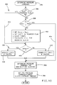
- the flow diagrams of Figures 10-12 set forth the clutch and PRV pressure determination algorithm generally referred to at the main loop instruction block 378 of Figure 9.
- the blocks designated generally by the reference numeral 388 are first executed to set up initial conditions if a shift is desired. If a shift is desired, the blocks designated generally by the reference numeral 390 are executed to develop pressure commands for the clutches involved in the shift. Thereafter, the instruction blocks 392 and 394 are executed to develop pressure commands for the nonshifting clutches and the pressure regulator valve PRV, completing the routine. As indicated at instruction block 394, the pressure command for the regulator valve PRV is set equal to the highest of the pressure commands for the various clutches.
- the blocks designated by the reference numeral 388 include the decision block 396 for determining if a shift is in progress as indicated by the "SHIFT IN PROGRESS" flag; the decision block 398 for determining if the actual speed ratio Ract (that is, No/Nt) is equal to the desired speed ratio Rdes determined at instruction block 376 of Figure 9; and the instruction block 400 for setting up the initial conditions for a ratio shift.
- the instruction block 400 is only executed when decision blocks 396 and 398 are both answered in the negative. In such case, instruction block 400 serves to set the old ratio variable, Rold, equal to Ract, to set the "SHIFT IN PROGRESS" flag, clear the shift timers, and to calculate the fill time tfill for the on-coming clutching device.
- the blocks designated by the reference numeral 390 include the decision block 406 for determining if the shift is an upshift or a downshift; the instruction block 408 for developing pressure commands for the active (shifting) clutches if the shift is an upshift; and the instruction block 410 for developing the pressure commands for the active clutches if the shift is a downshift.
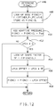
- the steps involved in the development of a typical power-on upshift i.e., instruction block 408 are set forth in the flow diagram of Figure 11.
- the control unit 270 executes a shift initializing routine comprising the blocks 412-416.
- the instruction blocks 414 and 416 are executed to determine the pressure parameters Pi, Pf and tf for the on-coming (ONC) and off-going (OFG) clutches, and to calculate the reference inertia phase interval Trip as a function of Nte, Rold and Rdes.
- decision block 412 is answered in the negative.
- Decision block 418 is then executed to determine if the fill phase of the shift is completed, as indicated by the "FILL COMP" flag. If not, the flow diagram branch, generally designated by the reference numeral 420, is executed; if so, the flow diagram branch, generally designated by the reference numeral 422, is executed.
- the flow diagram branch 420 includes a fill initializing routine comprising the blocks 424 and 426 and a fill completion routine comprising the blocks 428 and 430.
- the "FILL COMP" flag is not set, and the decision block 424 of the fill initializing routine is executed to determine if the fill phase has started, as indicated by the "FILL START" flag.
- the "FILL START" flag is not set, and instruction block 426 is executed to set the energization duty cycle of the on-coming clutch, DC(ONC), equal to 100%, to set the "FILL START” flag, and to start a FILL TIMER.
- decision block 424 is answered in the affirmative, and execution of instruction block 426 is skipped.
- Decision block 428 of the fill completion routine determines if the count in FILL TIMER is greater than or equal to the fill time tfill determined at instruction block 400 of Figure 10. If so, instruction block 430 is executed to save the entry turbine speed Nte, to set the "FILL COMP" flag, and to start the inertia phase timer, IP TIMER. If decision block 428 is answered in the negative, the fill phase is incomplete, and execution of the instruction block 430 is skipped.
- the flow diagram branch 422 is executed to complete the shift.
- the instruction block 436 is executed to calculate the value of %RATCOMP.
- the decision blocks 438 and 440 are executed to determine if the count in IP TIMER is at a maximum value, MAX, or if the term %RATCOMP is substantially equal to 100%. If either of the decision blocks 438 or 440 are answered in the affirmative, the shift is complete and instruction block 442 is executed to reset the "SHIFT IN PROGRESS" flag, to set the on-coming duty cycle, DC(ONC), equal to 100%, and to set the off-going duty cycle, DC(OFG), equal to 0%.
- instruction blocks 444 and 446 are executed to determine the off-going and on-coming pressure commands, P(OFG) and P(ONC).
- the off-going pressure command P(OFG) may be simply set to zero, or reduced to zero at a predetermined rate.
- the development of the on-coming pressure P(ONC) is set forth in detail in the flow diagram of Figure 12.
- the blocks 448-450 are first executed to look-up the scheduled open loop on-coming pressure command P(ONC)OL, and to add the appropriate adaptive correction, if any, to form the on-coming pressure command P(ONC).
- the open-loop on-coming pressure P(ONC)OL is determined as a function of IP TIMER and the Pi, Pf and tf values determined at instruction block 414 of Figure 11. If the LPCA term is nonzero -- that is, if there is an additive or subtractive adaptive correction common to each of the clutches 30-34 -- as determined at block 452, the blocks 454-458 are executed to remove a pressure-dependent portion of the adaptive correction amount.
- the block 454 determines the shape factor SF as a function of the scheduled pressure P(ONC)OL per the relationship depicted in Figure 7.
- the blocks 456-458 reduce the pressure command P(ONC) by the LPCA Offset, which is determined according to the product of LPCA and the shape factor SF.
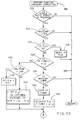
- the flow diagram of Figures 13-14 details the adaptive pressure correction routine referenced by the main flow diagram instruction block 382 of Figure 9.
- the routine comprises the steps of obtaining a measure Tip of the inertia phase interval, comparing Tip to a reference interval Trip to obtain an inertia phase error term Eip, and developing an adaptive correction amount in relation to Eip and the time integral of Eip.
- the measured interval begins when the ratio shift is 15% complete and ends when the ratio shift is 85% complete, as judged by the term %RATCOMP.
- the routine includes an initializing portion, an interval measurement portion and a correction portion.
- the initializing portion comprises the blocks 520-526; the interval measurement portion comprises the blocks 528-540; and the correction portion comprises the blocks 558-562.
- the decision blocks 520 and 522 are executed to determine if a single ratio upshift is in progress, and if the ratio shift is at least 15% complete, as judged by the term, %RATCOMP. If either of the decision blocks 520 and 522 are answered in the negative, the remainder of the flow diagram is skipped, as indicated by the flow diagram return line 550. When both are answered in the affirmative, the decision block 524 is executed to determine if the IP flag is set. This flag marks the beginning of the measured inertia phase interval, and is set by the instruction block 526 the first time that decision block 524 is executed. Thereafter, instruction block 524 is answered in the negative, and the measurement portion of the routine is entered.
- the decision block 558 is first executed to determine if the various parameters monitored in the course of the shift are indicative of an adaptable shift. Such parameters may include on-coming pressure in excess of a threshold value, stable throttle position, positive torque, and satisfactory oil temperature throughout the shift. If decision block 558 is answered in the affirmative, an adaptive pressure correction may be reliably made and the instruction blocks 560 and 562 are executed to update the low and high torque data points of the designated correction table in relation to the error Eip and the time integral of Eip.
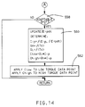
- the instruction block 560 updates the time integral of Eip and calculates a number of terms including the inertia phase pressure correction Cip, the gain factors GH and GL, and the actual data point correction amounts Chigh and Clow. Instruction block 562 then applies the data point correction amounts Chigh and Clow to the high and low torque data points of the designated table.
- the correction amount Cip is determined as a function of Eip and the time integral of Eip, and the gain factors GL and GH are determined as a function of the torque variable Tv as described in the above-referenced US patent no. 4,653,350.
- the respective gain factors are multiplied by the correction amount Cip to determine the data point correction amounts Chigh and Clow.
- the pressure supplied to the subject clutching device will result in an inertia phase interval more nearly equal to the reference interval Trip, and a more nearly optimum quality shift.
- the block 580 is executed to store minimum of the three correction amounts to the Line Pressure Characterization term LPCA. If there is no common positive or negative component to the adaptive correction amounts, as determined by blocks 570-578, the block 582 is executed to set the LPCA term to zero, completing the routine.
Landscapes
- Engineering & Computer Science (AREA)
- General Engineering & Computer Science (AREA)
- Physics & Mathematics (AREA)
- Fluid Mechanics (AREA)
- Mechanical Engineering (AREA)
- Control Of Transmission Device (AREA)
- Arrangement Of Transmissions (AREA)
Applications Claiming Priority (2)
| Application Number | Priority Date | Filing Date | Title |
|---|---|---|---|
| US07/722,756 US5086665A (en) | 1991-06-27 | 1991-06-27 | Adaptive shift pressure characterization of an electronically controlled automatic transmission |
| US722756 | 1991-06-27 |
Publications (1)
| Publication Number | Publication Date |
|---|---|
| EP0520531A1 true EP0520531A1 (de) | 1992-12-30 |
Family
ID=24903248
Family Applications (1)
| Application Number | Title | Priority Date | Filing Date |
|---|---|---|---|
| EP92201502A Withdrawn EP0520531A1 (de) | 1991-06-27 | 1992-05-25 | Verfahren zur adaptiven Drucksteuerung bei einem automatischen Schaltgetriebe |
Country Status (4)
| Country | Link |
|---|---|
| US (1) | US5086665A (de) |
| EP (1) | EP0520531A1 (de) |
| JP (1) | JPH05187537A (de) |
| CA (1) | CA2066340A1 (de) |
Cited By (1)
| Publication number | Priority date | Publication date | Assignee | Title |
|---|---|---|---|---|
| FR2764027A1 (fr) * | 1997-05-27 | 1998-12-04 | Aisin Seiki | Dispositif de commande d'un systeme de changement de vitesses automatique pour les voitures |
Families Citing this family (8)
| Publication number | Priority date | Publication date | Assignee | Title |
|---|---|---|---|---|
| US5503601A (en) * | 1992-02-18 | 1996-04-02 | Bastio; Michael J. | Automatic transmission performance improvement kit |
| US5251509A (en) * | 1992-04-03 | 1993-10-12 | General Motors Corporation | Adaptive pressure control for an automatic transmission |
| US5449329A (en) * | 1993-07-20 | 1995-09-12 | Deere & Company | Method for controlling transmission control clutches |
| US5470288A (en) * | 1993-10-06 | 1995-11-28 | Ford Motor Company | Engine torque compensation shift scheduling of an automatic transmission for motor vehicles |
| US5475590A (en) * | 1993-10-22 | 1995-12-12 | Ford Motor Company | Automatic transmission torque converter bypass clutch control using engine torque compensation |
| JP3956156B2 (ja) * | 1995-03-16 | 2007-08-08 | アイシン・エィ・ダブリュ株式会社 | 自動変速機の変速制御装置 |
| US5737712A (en) * | 1996-04-03 | 1998-04-07 | General Motors Corporation | Fuzzy logic adaptive shift control |
| DE10042146B4 (de) * | 2000-08-26 | 2020-01-16 | Zf Friedrichshafen Ag | Verfahren zur Steuerung eines Getriebes |
Citations (5)
| Publication number | Priority date | Publication date | Assignee | Title |
|---|---|---|---|---|
| US4653350A (en) * | 1985-11-29 | 1987-03-31 | General Motors Corporation | Adaptive direct pressure shift control for a motor vehicle transmission |
| US4707789A (en) * | 1985-11-29 | 1987-11-17 | General Motors Corporation | Adaptive direct pressure shift control for a motor vehicle transmission |
| EP0322111A2 (de) * | 1987-12-22 | 1989-06-28 | General Motors Corporation | Ereignisfolgenbedingtes Kupplung-zu-Kupplung-Herunterschalten für ein elektronisch gesteuertes automatisches Getriebe |
| WO1990004732A1 (de) * | 1988-10-26 | 1990-05-31 | Zahnradfabrik Friedrichshafen Ag | Elektronisch-hydraulische steuereinrichtung eines automatisch schaltenden kraftfahrzeuggetriebes |
| EP0414901A1 (de) * | 1988-11-24 | 1991-03-06 | Kabushiki Kaisha Komatsu Seisakusho | Verfahren und vorrichtung zur steuerung von getrieben |
Family Cites Families (8)
| Publication number | Priority date | Publication date | Assignee | Title |
|---|---|---|---|---|
| JPS5833427B2 (ja) * | 1979-03-14 | 1983-07-19 | トヨタ自動車株式会社 | 車輌用変速機の切換制御装置 |
| SE417413B (sv) * | 1979-06-28 | 1981-03-16 | Volvo Bm | Sett att styra en kraftoverforingsanordning samt anordning for utforande av settet |
| US4283970A (en) * | 1979-07-02 | 1981-08-18 | General Motors Corporation | Automatic transmission line pressure control |
| US4318311A (en) * | 1980-03-31 | 1982-03-09 | General Motors Corporation | Centrifugally actuated valve for transmission |
| JPS6229425A (ja) * | 1985-07-30 | 1987-02-07 | Mazda Motor Corp | 自動車の変速時期指示装置 |
| JP2605840B2 (ja) * | 1988-11-16 | 1997-04-30 | 日産自動車株式会社 | 無段変速機の変速制御装置 |
| JP2930973B2 (ja) * | 1989-06-29 | 1999-08-09 | アイシン・エィ・ダブリュ株式会社 | 自動変速機における油圧制御装置 |
| US5036729A (en) * | 1990-10-23 | 1991-08-06 | Saturn Corporation | Coast-sync-coast downshift control method for clutch-to-clutch transmission shifting |
-
1991
- 1991-06-27 US US07/722,756 patent/US5086665A/en not_active Expired - Fee Related
-
1992
- 1992-04-16 CA CA002066340A patent/CA2066340A1/en not_active Abandoned
- 1992-05-25 EP EP92201502A patent/EP0520531A1/de not_active Withdrawn
- 1992-06-29 JP JP4170787A patent/JPH05187537A/ja active Pending
Patent Citations (5)
| Publication number | Priority date | Publication date | Assignee | Title |
|---|---|---|---|---|
| US4653350A (en) * | 1985-11-29 | 1987-03-31 | General Motors Corporation | Adaptive direct pressure shift control for a motor vehicle transmission |
| US4707789A (en) * | 1985-11-29 | 1987-11-17 | General Motors Corporation | Adaptive direct pressure shift control for a motor vehicle transmission |
| EP0322111A2 (de) * | 1987-12-22 | 1989-06-28 | General Motors Corporation | Ereignisfolgenbedingtes Kupplung-zu-Kupplung-Herunterschalten für ein elektronisch gesteuertes automatisches Getriebe |
| WO1990004732A1 (de) * | 1988-10-26 | 1990-05-31 | Zahnradfabrik Friedrichshafen Ag | Elektronisch-hydraulische steuereinrichtung eines automatisch schaltenden kraftfahrzeuggetriebes |
| EP0414901A1 (de) * | 1988-11-24 | 1991-03-06 | Kabushiki Kaisha Komatsu Seisakusho | Verfahren und vorrichtung zur steuerung von getrieben |
Cited By (1)
| Publication number | Priority date | Publication date | Assignee | Title |
|---|---|---|---|---|
| FR2764027A1 (fr) * | 1997-05-27 | 1998-12-04 | Aisin Seiki | Dispositif de commande d'un systeme de changement de vitesses automatique pour les voitures |
Also Published As
| Publication number | Publication date |
|---|---|
| US5086665A (en) | 1992-02-11 |
| CA2066340A1 (en) | 1992-12-28 |
| JPH05187537A (ja) | 1993-07-27 |
Similar Documents
| Publication | Publication Date | Title |
|---|---|---|
| US5119695A (en) | Open-loop clutch-to-clutch upshift control having clutch overlap regulation | |
| EP0525853B1 (de) | Verfahren zur Steuerung eines automatischen Getriebes | |
| US5151858A (en) | Multiple mode adaptive pressure control for an automatic transmission | |
| US4653351A (en) | Clutch-to-clutch power-on downshifting in a motor vehicle automatic transmission | |
| CA1241093A (en) | Adaptive direct pressure shift control for a motor vehicle transmission | |
| CA1254974A (en) | Adaptive direct pressure shift control for a motor vehicle transmission | |
| US5129286A (en) | Engine torque management for engine speed flare suppression for clutch-to-clutch-upshifting | |
| US5782711A (en) | Hydraulic pressure control apparatus for an automatic transmission | |
| EP0482689B1 (de) | Steuerverfahren zum Herunterschalten eines Getriebes im Schiebebetrieb | |
| US5070746A (en) | Shift scheduling method for clutch energy limitation | |
| JP2672063B2 (ja) | 自動変速機の制御装置 | |
| US5086665A (en) | Adaptive shift pressure characterization of an electronically controlled automatic transmission | |
| EP0574061B1 (de) | Steuerung für ein automatisches Getriebe | |
| EP0668456A2 (de) | Verfahren und Einrichtung zur Steuerung eines Gangwechsels in einem automatischen Getriebe |
Legal Events
| Date | Code | Title | Description |
|---|---|---|---|
| PUAI | Public reference made under article 153(3) epc to a published international application that has entered the european phase |
Free format text: ORIGINAL CODE: 0009012 |
|
| AK | Designated contracting states |
Kind code of ref document: A1 Designated state(s): DE FR GB |
|
| 17P | Request for examination filed |
Effective date: 19921110 |
|
| 17Q | First examination report despatched |
Effective date: 19940506 |
|
| STAA | Information on the status of an ep patent application or granted ep patent |
Free format text: STATUS: THE APPLICATION IS DEEMED TO BE WITHDRAWN |
|
| 18D | Application deemed to be withdrawn |
Effective date: 19941109 |