EP0520976A2 - Electrode pour capteur polarographique - Google Patents
Electrode pour capteur polarographique Download PDFInfo
- Publication number
- EP0520976A2 EP0520976A2 EP92890111A EP92890111A EP0520976A2 EP 0520976 A2 EP0520976 A2 EP 0520976A2 EP 92890111 A EP92890111 A EP 92890111A EP 92890111 A EP92890111 A EP 92890111A EP 0520976 A2 EP0520976 A2 EP 0520976A2
- Authority
- EP
- European Patent Office
- Prior art keywords
- wire
- sheath
- wires
- electrode
- drain wire
- Prior art date
- Legal status (The legal status is an assumption and is not a legal conclusion. Google has not performed a legal analysis and makes no representation as to the accuracy of the status listed.)
- Withdrawn
Links
Images


Classifications
-
- G—PHYSICS
- G01—MEASURING; TESTING
- G01N—INVESTIGATING OR ANALYSING MATERIALS BY DETERMINING THEIR CHEMICAL OR PHYSICAL PROPERTIES
- G01N27/00—Investigating or analysing materials by the use of electric, electrochemical, or magnetic means
- G01N27/26—Investigating or analysing materials by the use of electric, electrochemical, or magnetic means by investigating electrochemical variables; by using electrolysis or electrophoresis
- G01N27/28—Electrolytic cell components
- G01N27/30—Electrodes, e.g. test electrodes; Half-cells
Definitions
- the present invention relates to an inner electrode of a polarographic electrode with an electrically insulating sheath, which receives a drain wire and has a reactive surface on the end face, which through the free cross-sectional areas of wires arranged in the sheath and in electrically conductive connection with the drain wire is formed, and on a method for producing an inner electrode.
- the wires of such an internal electrode are as thin as possible, their diameter is e.g. only 0.01 mm, and relatively long. Furthermore, they must be smooth in the electrode, above all kink-free and, of course, melted without interruption and have good electrical contact with the drain wire. Because of these requirements and the fineness of the wires, the manufacture of such electrodes is difficult.
- an inner electrode of the type mentioned has become known, which is manufactured as follows. First, the lead wire and a round glass rod are firmly connected to each other to form a hemispherical transition from the thinner lead wire to the thicker glass rod. At the transition forming a support surface, the fine wires are now connected in an electrically conductive manner to the drain wire, bent over the hemispherical support surface and glued to the glass rod by means of an adhesive. Then the structural unit consisting of lead wire and glass rod with adjacent wires is inserted into a glass envelope, the inside diameter of which corresponds to that of the glass rod with the electrode wires glued on.
- the glass tube end is fused to the glass rod so that the fine electrode wires are completely covered by the glass.
- that part of the electrode tip is sought out under the microscope at which the melted-in wires are most evenly distributed and the electrode is cut off at this point.
- a disadvantage of this inner electrode is the extremely complex manufacturing process, in which high exclusion rates and thus also high costs arise.
- US Pat. No. 3,700,580 shows an electrochemical sensor in which the inner electrode is formed by a wire which is connected to a stripping wire, the wire including the connection point being cast in epoxy resin.
- a similar design is also known from GB-PS 2 114 304.
- the object of the present invention is to propose an inner electrode of the type described at the outset, which can be manufactured more easily without restricting the measuring sensitivity.
- connection point with the drain wire are cast in a manner known per se into a plastic compound filling the front region of the cover and that the cover, based on the inside diameter on the surface, is between the connection point and the reactive surface has lying cross-sectional constriction, against which the wires lie and are aligned substantially parallel to the axis of the sheath.
- a method according to the invention for producing such an internal electrode is characterized in that the lead wire, together with the protruding wire ends, is drawn into the envelope at the free end of the lead wire, so that they rest on the cross-sectional constriction of the envelope and are aligned essentially parallel to the axis of the envelope that the end region of the casing is poured out with a plastic compound in a manner known per se, and that the end surface is subjected to a processing (eg grinding) exposing the cross-sectional surfaces of the wire ends after the hardening of the plastic compound.
- a processing eg grinding
- Electrodes for measuring O2, glucose, lactate, etc.
- drain wire and the wires ending in the reactive surface are achieved in that two wires form the free ends of a piece of wire and the drain wire has a flat point at the connection point to the wire piece, which comprises the wire piece in a hook shape.
- solder or adhesive connections are also possible between the drain wire and the fine wires.
- the sheath of the inner electrode has a shoulder on which the flat point of the drain wire lies.
- the drain wire can be drawn in without a precise adjustment up to a stop.
- the sleeve of the electrode can be made of glass, ceramic or plastic, the plastic mass of an epoxy resin (as known per se), polyester or liquid polymethyl methacrylate and the wires of a noble metal, a noble metal alloy or carbon fibers.
- the insulating sheath can thus be a plastic part which can be produced mechanically or by injection molding, all materials being suitable which form an adequate bond with the casting compound.
- Gold, platinum, silder, iridium and carbon fibers are particularly suitable as wire materials, whereby - by using a plastic casting compound - wire materials are also possible which cannot be melted into glass.
- the requirements for the casting compound are above all low shrinkage losses when curing, good adhesion to both Wires as well as on the casing material, good insulation, low water absorption, low gas permeability and good mechanical workability.
- Another advantage of the inner electrode according to the invention lies in the extremely inexpensive manufacturing process.
- the inner electrode 1 shown in FIG. 1 has an electrically insulating sheath 2 which encloses a drain wire 3.
- the reactive surface 4 of the electrode 1 is formed by the free cross-sectional areas of the wires 5, which are in an electrically conductive connection with the lead wire 3.
- the wires 5 and their connection point with the drain wire 3 are cast into a plastic mass 6 filling the end region of the sheath 2.
- the inner diameter D of the sheath 2 has a cross-sectional constriction 7, against which the wires 5 rest when the drain wire 3 is inserted and are aligned with the reactive surface 4.
- first several drain wires 3 are made of jumper wire, for example made of bare copper, galvanized, silver-plated or silver, with a diameter of approximately 0.5 mm cut and cold-formed at one end, so that a flat spot 9 of about 1 mm width is formed.
- the discharge wires 3 are lined up with their bottle locations 9 at a distance, so that a fine wire, for example made of platinum, with a diameter between 5 and 50 ⁇ m can be placed over the bottle locations 9 (FIG. 3). After that the Bottle points 9 folded over in a hook shape, the platinum wire being gripped and held.
- each lead wire 3 clamps a piece of wire 8, the free ends of which extend essentially at right angles to form the wires 5.
- the conductivity of the connection point between the drain wire 3 and piece of wire 8 can be increased by a drop of conductive adhesive (arrow 8 ') (Fig. 4).
- the discharge wire 3 is then drawn into the sheath 2 at its free end until its bottle point 9 lies against a shoulder 10 of the sheath 2, the wire ends or wires 5 being aligned by the cross-sectional constriction 7 in the direction of the reactive surface 4.
- the front area of the casing 2 is now poured out with a plastic compound 6. After curing, protruding parts of the plastic mass are removed mechanically, for example by grinding, and the surface is polished.
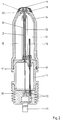
- FIG. 2 shows a polarographic electrode with an inserted inner electrode 1, which is held by ribs 12 formed on the electrode body 11. Between the electrode body 11 and the inner electrode 1, the lead wire 3 is surrounded by an elastic tube 13 and electrically insulated. In the electrolyte-filled interior 15 of the polarographic electrode formed by a housing 14, a silver pin held by the electrode body 11 projects as a reference electrode 16. Expansions caused by temperature and construction, e.g. The air in the electrolyte space is compensated for by the elastic hose 13.
- the housing 14 is held over two grid positions 17, 17 'on the electrode body 11 and has a soft cap 18 at the point of passage for the inner electrode 1, which carries a membrane 19 which is selective for the measuring substance.
- the integrally formed ribs 12 engage in recesses 23 of the housing 14 so that it cannot be rotated and thus the membrane 19 is not additionally loaded.
- the cap 18 has the function of the membrane holder and also serves as a seal against a measuring chamber.
- the housing 14 When inserting the electrode in a measuring chamber, the housing 14 is pressed into the second grid position 17 'and only then the membrane 19 is stretched onto the inner electrode 1, thereby determining its service life through effective use in the measuring chamber and thus significantly extending it.
- the slight overpressure resulting from the insertion is also compensated for by the elastic hose 13.
- the polarographic electrode has a plug cap 20 with an integrated plug 21, the electrical connection to the drain wire 3 on the one hand and to the reference electrode 16 on the other hand being made via conductive adhesive connections 22.
Landscapes
- Chemical & Material Sciences (AREA)
- Life Sciences & Earth Sciences (AREA)
- Health & Medical Sciences (AREA)
- Biochemistry (AREA)
- Chemical Kinetics & Catalysis (AREA)
- Electrochemistry (AREA)
- Physics & Mathematics (AREA)
- Analytical Chemistry (AREA)
- Molecular Biology (AREA)
- General Health & Medical Sciences (AREA)
- General Physics & Mathematics (AREA)
- Immunology (AREA)
- Pathology (AREA)
- Investigating Or Analyzing Materials By The Use Of Electric Means (AREA)
- Thermistors And Varistors (AREA)
- Connections Effected By Soldering, Adhesion, Or Permanent Deformation (AREA)
Applications Claiming Priority (2)
| Application Number | Priority Date | Filing Date | Title |
|---|---|---|---|
| AT1291/91 | 1991-06-27 | ||
| AT0129191A AT395915B (de) | 1991-06-27 | 1991-06-27 | Innenelektrode einer polarographischen elektrode |
Publications (2)
| Publication Number | Publication Date |
|---|---|
| EP0520976A2 true EP0520976A2 (fr) | 1992-12-30 |
| EP0520976A3 EP0520976A3 (en) | 1993-05-05 |
Family
ID=3510710
Family Applications (1)
| Application Number | Title | Priority Date | Filing Date |
|---|---|---|---|
| EP19920890111 Withdrawn EP0520976A3 (en) | 1991-06-27 | 1992-05-11 | Polarographic sensor electrode |
Country Status (4)
| Country | Link |
|---|---|
| US (1) | US5266180A (fr) |
| EP (1) | EP0520976A3 (fr) |
| JP (1) | JPH0820399B2 (fr) |
| AT (1) | AT395915B (fr) |
Families Citing this family (5)
| Publication number | Priority date | Publication date | Assignee | Title |
|---|---|---|---|---|
| US5932175A (en) * | 1996-09-25 | 1999-08-03 | Via Medical Corporation | Sensor apparatus for use in measuring a parameter of a fluid sample |
| DE10050648C2 (de) * | 2000-10-12 | 2003-11-06 | Fraunhofer Ges Forschung | Chirurgisches Instrument |
| DE10340888B3 (de) * | 2003-09-04 | 2005-04-21 | Atotech Deutschland Gmbh | Stromversorgungseinrichtung in einer Vorrichtung zur elektrochemischen Behandlung |
| US8019436B2 (en) * | 2004-06-25 | 2011-09-13 | Cochlear Limited | Electrode assembly for a stimulating medical device |
| DE102012214801A1 (de) * | 2012-08-21 | 2014-02-27 | Siemens Aktiengesellschaft | Verfahren zur Herstellung eines Sensorinstruments und Sensorinstrument |
Family Cites Families (6)
| Publication number | Priority date | Publication date | Assignee | Title |
|---|---|---|---|---|
| GB1325873A (en) * | 1969-08-11 | 1973-08-08 | Nat Res Dev | Apparatus for measuring the concentration of dissolved oxygen in an queous solution |
| US3999284A (en) * | 1973-05-31 | 1976-12-28 | Mediscience Technology Corporation | Method for making a polarographic sensing means |
| CH568565A5 (fr) * | 1974-03-15 | 1975-10-31 | Avl Verbrennungskraft Messtech | |
| JPS5648549A (en) * | 1979-09-24 | 1981-05-01 | Albery Wyndham John | Electrochemical sensor for oxygen* halogen and nitrous oxide |
| GB2114304B (en) * | 1982-02-01 | 1986-11-12 | Distillers Company The | Electrochemical membrane sensor |
| JPS5910611U (ja) * | 1982-07-15 | 1984-01-23 | 株式会社ムラオ | 装身用鎖のとめ金具 |
-
1991
- 1991-06-27 AT AT0129191A patent/AT395915B/de not_active IP Right Cessation
-
1992
- 1992-05-11 EP EP19920890111 patent/EP0520976A3/de not_active Withdrawn
- 1992-06-05 US US07/894,549 patent/US5266180A/en not_active Expired - Fee Related
- 1992-06-24 JP JP4166382A patent/JPH0820399B2/ja not_active Expired - Lifetime
Also Published As
| Publication number | Publication date |
|---|---|
| EP0520976A3 (en) | 1993-05-05 |
| AT395915B (de) | 1993-04-26 |
| JPH05296966A (ja) | 1993-11-12 |
| JPH0820399B2 (ja) | 1996-03-04 |
| ATA129191A (de) | 1992-08-15 |
| US5266180A (en) | 1993-11-30 |
Similar Documents
| Publication | Publication Date | Title |
|---|---|---|
| DE2910909A1 (de) | Verfahren zum herstellen einer lichtleiterverbindung sowie steckverbindungsbaugruppe hierzu | |
| DE2842697B1 (de) | Galvanisches Element und Verfahren zu seiner Herstellung | |
| DE2845022A1 (de) | Elektronisches schaltungsbauelement | |
| DE3114441A1 (de) | Elektrochemische messelektrodeneinrichtung | |
| DE3342753A1 (de) | Keramische heizvorrichtung | |
| DE3537051A1 (de) | Sauerstoffsensor | |
| US4576174A (en) | Micro electrode | |
| EP0337141A1 (fr) | Traversée de fibre optique pour des modules optoélectroniques et procédé pour sa fabrication | |
| DE2436328A1 (de) | Akustischer wandler und verfahren zu seiner herstellung | |
| AT395915B (de) | Innenelektrode einer polarographischen elektrode | |
| DE19813468C1 (de) | Sensorbauelement | |
| DE19721101B4 (de) | Elektronische Komponenten mit Harz-überzogenen Zuleitungsanschlüssen | |
| CH638616A5 (de) | Elektrodenkopf fuer eine elektrode. | |
| DE3729164C2 (de) | Meßfühler zur Messung der Sauerstoffkonzentration in Gasen | |
| DE2703338C2 (fr) | ||
| DE3150435C2 (fr) | ||
| DE69118635T2 (de) | Optische Halbleiter-Vorrichtung | |
| DE2427502A1 (de) | Alkalische knopf-batterie | |
| DE2443863C2 (de) | Polarographische Zelle | |
| DE102020126833A1 (de) | Sensoranordnung und Verfahren zur Herstellung einer Sensoranordnung | |
| CH501919A (de) | Glaselektrode zum Messen von Ionenkonzentrationen | |
| EP1525462B1 (fr) | Procede pour produire des sondes ph | |
| EP0517032B1 (fr) | Electrode en forme de cartouche pour des mesures potentiométriques et son procédé de fabrication | |
| DE3105089A1 (de) | "sauerstoff-sensor" | |
| US3965383A (en) | Multi-wire oxygen electrode and method of manufacturing the same |
Legal Events
| Date | Code | Title | Description |
|---|---|---|---|
| PUAI | Public reference made under article 153(3) epc to a published international application that has entered the european phase |
Free format text: ORIGINAL CODE: 0009012 |
|
| AK | Designated contracting states |
Kind code of ref document: A2 Designated state(s): DE DK FR GB |
|
| GBC | Gb: translation of claims filed (gb section 78(7)/1977) | ||
| RTI1 | Title (correction) | ||
| PUAL | Search report despatched |
Free format text: ORIGINAL CODE: 0009013 |
|
| EL | Fr: translation of claims filed | ||
| AK | Designated contracting states |
Kind code of ref document: A3 Designated state(s): DE DK FR GB |
|
| 17P | Request for examination filed |
Effective date: 19930525 |
|
| 17Q | First examination report despatched |
Effective date: 19940606 |
|
| 18D | Application deemed to be withdrawn |
Effective date: 19951201 |