EP0521181A1 - Elément chauffant à PTC - Google Patents
Elément chauffant à PTC Download PDFInfo
- Publication number
- EP0521181A1 EP0521181A1 EP91111056A EP91111056A EP0521181A1 EP 0521181 A1 EP0521181 A1 EP 0521181A1 EP 91111056 A EP91111056 A EP 91111056A EP 91111056 A EP91111056 A EP 91111056A EP 0521181 A1 EP0521181 A1 EP 0521181A1
- Authority
- EP
- European Patent Office
- Prior art keywords
- insulating frame
- opening
- ptc
- pin
- electrode plate
- Prior art date
- Legal status (The legal status is an assumption and is not a legal conclusion. Google has not performed a legal analysis and makes no representation as to the accuracy of the status listed.)
- Granted
Links
Images


Classifications
-
- H—ELECTRICITY
- H05—ELECTRIC TECHNIQUES NOT OTHERWISE PROVIDED FOR
- H05B—ELECTRIC HEATING; ELECTRIC LIGHT SOURCES NOT OTHERWISE PROVIDED FOR; CIRCUIT ARRANGEMENTS FOR ELECTRIC LIGHT SOURCES, IN GENERAL
- H05B3/00—Ohmic-resistance heating
- H05B3/10—Heating elements characterised by the composition or nature of the materials or by the arrangement of the conductor
- H05B3/12—Heating elements characterised by the composition or nature of the materials or by the arrangement of the conductor characterised by the composition or nature of the conductive material
- H05B3/14—Heating elements characterised by the composition or nature of the materials or by the arrangement of the conductor characterised by the composition or nature of the conductive material the material being non-metallic
-
- H—ELECTRICITY
- H01—ELECTRIC ELEMENTS
- H01C—RESISTORS
- H01C1/00—Details
- H01C1/14—Terminals or tapping points specially adapted for resistors; Arrangements of terminals or tapping points on resistors
- H01C1/1406—Terminals or electrodes formed on resistive elements having positive temperature coefficient
-
- H—ELECTRICITY
- H01—ELECTRIC ELEMENTS
- H01C—RESISTORS
- H01C1/00—Details
- H01C1/14—Terminals or tapping points specially adapted for resistors; Arrangements of terminals or tapping points on resistors
- H01C1/144—Terminals or tapping points specially adapted for resistors; Arrangements of terminals or tapping points on resistors the terminals or tapping points being welded or soldered
-
- H—ELECTRICITY
- H01—ELECTRIC ELEMENTS
- H01C—RESISTORS
- H01C7/00—Non-adjustable resistors formed as one or more layers or coatings; Non-adjustable resistors made from powdered conducting material or powdered semi-conducting material with or without insulating material
- H01C7/02—Non-adjustable resistors formed as one or more layers or coatings; Non-adjustable resistors made from powdered conducting material or powdered semi-conducting material with or without insulating material having positive temperature coefficient
Definitions
- the present invention relates to a PTC heater according to the preamble of claim 1.
- a heater is known from DE-PS 30 42 420.
- Such radiators usually have several flat heating elements.
- the heating elements consist of a positioning frame made of insulating material, which has several openings in which form-adapted PTC elements are arranged.
- the positioning frame is covered on both sides by electrode plates so that the PTC elements are in contact with both electrode plates and are prevented from falling out of the openings.
- a problematic point in the production of such radiators or heating elements is the connection between the electrode plates with the position or insulating frame. With a number of previously known heating elements, this is achieved by means of suitable, attached clamping devices.
- the attachment of the electrode plates to the position or insulating frame is achieved by means of connecting lugs formed on the electrode plates, which are inserted through openings in the position frame and bent over on the other side of the position frame.
- Electrode plates on the positioning frame is that the electrode plates have to be made of a relatively strong sheet metal so that the connecting lugs formed on the electrode plate and having the same sheet thickness are sufficiently strong so that a by bending the connecting lugs on the other side of the positioning frame permanent and firm connection can be achieved.
- High sheet thicknesses for the electrode plates are undesirable, however, because they hinder the heat conduction between the heating PTC elements and the environment.
- Another disadvantage of attaching the electrode plates to the positioning or insulating frame by means of connecting lugs is the great outlay for assembly. The connecting lugs can easily bend when the electrodes are joined together with the positioning frame, so that manual, time-consuming re-erection of the connecting lugs is necessary.
- the object of the present invention is therefore to provide a PTC radiator in which a permanent, firm connection between the electrodes and the insulating frame can be produced in a simple and automation-appropriate manner.
- the invention provides a PTC heating element in which, in addition to a firm and permanent connection between the electrode plates and the insulating frame, which can be produced easily and in a manner suitable for automation, electrode plates of very low thickness can be used.
- the development according to the features of claim 2 of the present invention has the advantage of a particularly simple type of connector.
- the plug connection consists only of a pin formed on the insulating frame and an opening provided on the electrode plate, the diameters of which are such that the pin sits in the opening of the electrode by means of a press fit, the plug connection is extremely easy to manufacture and this lowers the manufacturing costs of the PTC radiator.
- Another advantage is the simple assembly of the electrodes with the insulating frame, which makes it easy to automate the assembly, which in turn lowers the manufacturing costs for the PTC radiator.
- the embodiment according to claim 3 of the present invention also has the advantage of an automation-appropriate and therefore cost-reducing possibility of connecting the electrode plates to the insulating frame.
- the particular advantage of this embodiment can be seen in the fact that the plug connection is completely flat, ie without elevations on the side of the electrode plate facing away from the insulating frame. As a result, the electrode can lie evenly on the body to be heated, so that good heat coverage is ensured.
- the embodiment of the present invention according to the features of claim 5 has the advantage that the hollow pins are easy to manufacture and can be easily expanded by means of an embossing mandrel inserted from the opposite side of the insulating frame.
- the embodiment of the present invention according to the features of claim 6, in which the electrodes are made of sheet metal strips with a thickness of less than 0.2 mm, preferably 0.1 mm, has the advantage that the electrodes, due to the small Starch have a particularly good thermal conductivity.
- the embodiment of the invention according to the features of claim 8 has the advantage that through the opening designed as a slot, the electrodes are firmly connected to the insulating frame, but can expand freely when heated, so that no tension and in particular, the electrodes are not bent open, as a result of which the contact between the PTC elements and the electrodes could deteriorate.
- each electrode reliably closes the openings covered by it, so that falling out of the PTC elements, even if they are very small, is reliably prevented.
- the PTC radiator has an insulating frame 1 with openings 2 and shape-adapted PCT resistance elements 3 used therein on.
- the flat insulating frame is surrounded on both sides by electrodes 4 and 4a, so that the PTC elements are held securely between the electrode plates 4 and 4a and are in contact with them.
- the electrode plates 4 and 4a are firmly connected to the insulating frame 1 by means of plug connections 5.
- the plug connections consist of pins 6 and 6 'and openings 7 and 7'.
- One of the electrode plates shown in FIG. 1 could also be designed in two pieces to achieve three heating levels. A first heating level would then correspond to heating only one PTC element, a second heating level to heating the other PTC element and a third heating level to heating both PTC elements simultaneously.
- the two-part electrode plate could be formed by two of the shorter electrode plates shown in FIG. 2.
- the pins are integrally formed on the electrode plates.
- the pins are inserted into the openings 7, which are dimensioned such that each electrode is press-fitted to the insulating frame.
- Each electrode is attached to the insulating frame with at least two such plug connections.
- each electrode plate is connected to the insulating frame at as many points as is necessary to hold the PTC elements securely in the openings.
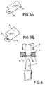
- FIGS. 3a and 3b show one possibility of how the pins can be manufactured extremely easily and in a manner suitable for automation.
- a cross slot 8 is punched in at the point where the pin is to be provided.
- the triangular, punched tongues 9 are then placed perpendicular to the electrode plate by means of a stamp, so that the pin 6 is formed.
- the insulating frame expediently has a bore with a profile according to FIG. 4.
- Fig. 4 shows a cross section through a plug connection 5 on the insulating frame. It can be seen that the bore of the opening 7 has a larger diameter in the outer regions than in the inner region of the bore.
- the pin 6 of the electrode 4 or 4a has a diameter which corresponds approximately to the diameter of the narrowed point 10 of the opening 7.
- the plug connections shown in FIGS. 1 and 4 have the advantage that after the electrode plate has been fastened to the insulating frame, no elevations occur on the surface of the electrode plate facing away from the insulating frame.
- the PTC radiator can therefore lie flat on the body to be heated, which ensures good heat conduction.
- each electrode plate 4 has cutouts 13 in the areas in which the openings for the respective other electrode plate are provided in the insulating frame. Such a recess is also necessary if the widening of the pegs shown in FIG. 4 is to be carried out with the aid of an embossing mandrel, since the widening of the pegs in one of the electrodes must not be blocked by the other electrode from access to the openings.
- the electrode plates are preferably made of a spring-hard brass sheet with a thickness of less than 0.2 mm, but preferably of 0.1 mm. Such thin brass sheets have excellent thermal conductivity, so that the heat given off by the PTC elements can be passed on to the environment.
- the pins 6 ' are not formed on the electrode plates 4 or 4a, but on the insulating frame 1 itself. Accordingly, the electrode plates 4 and 4a have openings 7 '.
- the pins 6 'and the openings 7' are dimensioned with respect to one another in such a way that the electrodes are press-fitted to the insulating frame 1 by means of an interference fit are connected.
- the openings 7 ' can also be designed as slots 7', so that a temperature-dependent expansion of the electrode plates to avoid mechanical stresses is made possible.
- the cutouts can in turn be useful if one of the electrode plates is designed in two pieces to achieve three heating levels.
- the recesses 13 enable the short electrodes arranged on a common side of the insulating frame to be arranged in a space-saving and contact-free manner so that they engage in the respective recess of the other electrode.
- the electrode plates 4 and 4a can be connected to the electrical supply lines 15 by a crimp connection 14 provided integrally on the electrode plates.
- a connection to the electrical lines 15 is also possible according to FIG. 1 via plugs 16 which are plugged onto tongues 17 formed on the electrode plates.
Landscapes
- Engineering & Computer Science (AREA)
- Microelectronics & Electronic Packaging (AREA)
- Ceramic Engineering (AREA)
- Physics & Mathematics (AREA)
- Electromagnetism (AREA)
- Resistance Heating (AREA)
Priority Applications (3)
| Application Number | Priority Date | Filing Date | Title |
|---|---|---|---|
| ES91111056T ES2086434T3 (es) | 1991-07-03 | 1991-07-03 | Dispositivo calentador de ptc. |
| DE59107483T DE59107483D1 (de) | 1991-07-03 | 1991-07-03 | PTC-Heizkörper |
| EP91111056A EP0521181B1 (fr) | 1991-07-03 | 1991-07-03 | Elément chauffant à PTC |
Applications Claiming Priority (1)
| Application Number | Priority Date | Filing Date | Title |
|---|---|---|---|
| EP91111056A EP0521181B1 (fr) | 1991-07-03 | 1991-07-03 | Elément chauffant à PTC |
Publications (2)
| Publication Number | Publication Date |
|---|---|
| EP0521181A1 true EP0521181A1 (fr) | 1993-01-07 |
| EP0521181B1 EP0521181B1 (fr) | 1996-02-28 |
Family
ID=8206895
Family Applications (1)
| Application Number | Title | Priority Date | Filing Date |
|---|---|---|---|
| EP91111056A Expired - Lifetime EP0521181B1 (fr) | 1991-07-03 | 1991-07-03 | Elément chauffant à PTC |
Country Status (3)
| Country | Link |
|---|---|
| EP (1) | EP0521181B1 (fr) |
| DE (1) | DE59107483D1 (fr) |
| ES (1) | ES2086434T3 (fr) |
Cited By (6)
| Publication number | Priority date | Publication date | Assignee | Title |
|---|---|---|---|---|
| EP1061776A1 (fr) * | 1999-06-15 | 2000-12-20 | David & Baader DBK Spezialfabrik elektrischer Apparate und Heizwiderstände GmbH | Dispositif de chauffage destiné au réchauffement de l'air |
| EP1033065A4 (fr) * | 1997-10-07 | 2001-08-08 | A T C T Advanced Thermal Chips | Dispositif chauffant a immersion et a coefficient de temperature positif |
| DE20121116U1 (de) * | 2001-12-21 | 2003-04-24 | Fritz Eichenauer GmbH & Co. KG, 76870 Kandel | Elektrische Heizeinrichtung zum Beheizen einer Flüssigkeit in einem Kfz |
| US8229289B2 (en) | 2006-03-21 | 2012-07-24 | Rittal Gmbh & Co. Kg | Condensate discharge by means of condensate evaporation in a cooling device |
| CN108151290A (zh) * | 2016-12-06 | 2018-06-12 | 埃贝赫卡腾有限两合公司 | 电加热装置和用于电加热装置的ptc加热元件 |
| DE102021112839B3 (de) | 2021-05-18 | 2022-06-09 | Ntt New Textile Technologies Gmbh | Verfahren zur Herstellung einer Verbindung zwischen einer Elektrode und einem elektrischen Leiter |
Citations (4)
| Publication number | Priority date | Publication date | Assignee | Title |
|---|---|---|---|---|
| US4242567A (en) * | 1978-06-05 | 1980-12-30 | General Electric Company | Electrically heated hair straightener and PTC heater assembly therefor |
| DE3042420A1 (de) * | 1980-11-11 | 1982-06-24 | Fritz Eichenauer GmbH & Co KG, 6744 Kandel | Elektrischer heizkoerper mit ein oder mehreren flachen, quaderfoermigen heizelementen |
| EP0054901A1 (fr) * | 1980-12-22 | 1982-06-30 | Kabelwerke Reinshagen GmbH | Dispositif de chauffage électrique |
| GB2181629A (en) * | 1985-09-27 | 1987-04-23 | Tdk Corp | Ptc heating device |
-
1991
- 1991-07-03 EP EP91111056A patent/EP0521181B1/fr not_active Expired - Lifetime
- 1991-07-03 DE DE59107483T patent/DE59107483D1/de not_active Expired - Fee Related
- 1991-07-03 ES ES91111056T patent/ES2086434T3/es not_active Expired - Lifetime
Patent Citations (4)
| Publication number | Priority date | Publication date | Assignee | Title |
|---|---|---|---|---|
| US4242567A (en) * | 1978-06-05 | 1980-12-30 | General Electric Company | Electrically heated hair straightener and PTC heater assembly therefor |
| DE3042420A1 (de) * | 1980-11-11 | 1982-06-24 | Fritz Eichenauer GmbH & Co KG, 6744 Kandel | Elektrischer heizkoerper mit ein oder mehreren flachen, quaderfoermigen heizelementen |
| EP0054901A1 (fr) * | 1980-12-22 | 1982-06-30 | Kabelwerke Reinshagen GmbH | Dispositif de chauffage électrique |
| GB2181629A (en) * | 1985-09-27 | 1987-04-23 | Tdk Corp | Ptc heating device |
Cited By (9)
| Publication number | Priority date | Publication date | Assignee | Title |
|---|---|---|---|---|
| EP1033065A4 (fr) * | 1997-10-07 | 2001-08-08 | A T C T Advanced Thermal Chips | Dispositif chauffant a immersion et a coefficient de temperature positif |
| EP1061776A1 (fr) * | 1999-06-15 | 2000-12-20 | David & Baader DBK Spezialfabrik elektrischer Apparate und Heizwiderstände GmbH | Dispositif de chauffage destiné au réchauffement de l'air |
| US6472645B1 (en) | 1999-06-15 | 2002-10-29 | David & Baader Spezialfabrik Elekrischer Apparate Und Heizwiderstande Gmbh | Air heating device |
| DE20121116U1 (de) * | 2001-12-21 | 2003-04-24 | Fritz Eichenauer GmbH & Co. KG, 76870 Kandel | Elektrische Heizeinrichtung zum Beheizen einer Flüssigkeit in einem Kfz |
| US8229289B2 (en) | 2006-03-21 | 2012-07-24 | Rittal Gmbh & Co. Kg | Condensate discharge by means of condensate evaporation in a cooling device |
| CN108151290A (zh) * | 2016-12-06 | 2018-06-12 | 埃贝赫卡腾有限两合公司 | 电加热装置和用于电加热装置的ptc加热元件 |
| CN108151290B (zh) * | 2016-12-06 | 2021-01-15 | 埃贝赫卡腾有限两合公司 | 电加热装置和用于电加热装置的ptc加热元件 |
| DE102021112839B3 (de) | 2021-05-18 | 2022-06-09 | Ntt New Textile Technologies Gmbh | Verfahren zur Herstellung einer Verbindung zwischen einer Elektrode und einem elektrischen Leiter |
| EP4092692A1 (fr) | 2021-05-18 | 2022-11-23 | NTT New Textile Technologies GmbH | Procédé d'établissement d'une connexion entre une électrode et un conducteur électrique |
Also Published As
| Publication number | Publication date |
|---|---|
| EP0521181B1 (fr) | 1996-02-28 |
| ES2086434T3 (es) | 1996-07-01 |
| DE59107483D1 (de) | 1996-04-04 |
Similar Documents
| Publication | Publication Date | Title |
|---|---|---|
| EP1391965B1 (fr) | Borne à ressort pour conducteur électrique | |
| EP2505931B2 (fr) | Dispositif de chauffage électrique doté d'un élément plat comprenant des pistes conductrices et procédé de fabrication d'un tel élément plat | |
| DE60000187T2 (de) | Koaxialverbinder zum Verbinden von zwei Leiterplatten | |
| DE19825971C1 (de) | Elektrisches Steckverbindungsteil | |
| EP0557744A1 (fr) | Interrupteur thermique | |
| EP3375048B1 (fr) | Contact à enficher | |
| EP3446367B1 (fr) | Contact enfichable | |
| DE69005126T2 (de) | Elektrischer Steckerstift. | |
| DE10257759A1 (de) | Elektrische Steckverbindung mit einem Gehäuse und einem Hochstromkontakt | |
| DE102008014337A1 (de) | Leiterplattenverbinder | |
| DE68909804T2 (de) | Elektrischer Steckverbinder. | |
| EP0521181B1 (fr) | Elément chauffant à PTC | |
| WO2011131310A1 (fr) | Prise de courant électrique | |
| DE2520884C3 (de) | Vorrichtung zum Aufbringen je eines Verbindungsstückes aus Isolierstoff an den beiden Enden des Mäanderbereiches eines Bimetallstreifens | |
| DE2345583C3 (de) | Steckerleiste | |
| DE2609291C2 (de) | Schraubenlose Anschlußklemme zur Stromübertragung von elektrischen Leitern | |
| DE20113884U1 (de) | Elektrischer Verbinder für eine Leiterplatte | |
| DE10212511B4 (de) | Querverbinder für Reihenklemmen | |
| DE4241242A1 (de) | Elektrischer Zustandsfühler | |
| EP0401330B1 (fr) | Radiateur a rayons infrarouges a quartz enfichable | |
| DE19945310C2 (de) | Steckverbinder | |
| DE19913552B4 (de) | Rotationsmäßig betätigbares elektrisches Bauteil mit einem durch einen Gewindeantrieb betätigten Gleitstück | |
| DE3932346C2 (de) | Elektrischer Steckverbinder | |
| DE3435823A1 (de) | Schalteranordnung mit in eine kontakthalterung eingeformten kontakten | |
| DE4110386C2 (de) | Steckverbinder |
Legal Events
| Date | Code | Title | Description |
|---|---|---|---|
| PUAI | Public reference made under article 153(3) epc to a published international application that has entered the european phase |
Free format text: ORIGINAL CODE: 0009012 |
|
| AK | Designated contracting states |
Kind code of ref document: A1 Designated state(s): AT BE CH DE DK ES FR GB GR IT LI LU NL SE |
|
| 17P | Request for examination filed |
Effective date: 19930125 |
|
| 17Q | First examination report despatched |
Effective date: 19940902 |
|
| GRAA | (expected) grant |
Free format text: ORIGINAL CODE: 0009210 |
|
| AK | Designated contracting states |
Kind code of ref document: B1 Designated state(s): DE ES FR GB IT |
|
| ITF | It: translation for a ep patent filed | ||
| REF | Corresponds to: |
Ref document number: 59107483 Country of ref document: DE Date of ref document: 19960404 |
|
| ET | Fr: translation filed | ||
| GBT | Gb: translation of ep patent filed (gb section 77(6)(a)/1977) |
Effective date: 19960426 |
|
| REG | Reference to a national code |
Ref country code: ES Ref legal event code: FG2A Ref document number: 2086434 Country of ref document: ES Kind code of ref document: T3 |
|
| PLBE | No opposition filed within time limit |
Free format text: ORIGINAL CODE: 0009261 |
|
| STAA | Information on the status of an ep patent application or granted ep patent |
Free format text: STATUS: NO OPPOSITION FILED WITHIN TIME LIMIT |
|
| 26N | No opposition filed | ||
| REG | Reference to a national code |
Ref country code: GB Ref legal event code: IF02 |
|
| PGFP | Annual fee paid to national office [announced via postgrant information from national office to epo] |
Ref country code: ES Payment date: 20070720 Year of fee payment: 17 |
|
| PGFP | Annual fee paid to national office [announced via postgrant information from national office to epo] |
Ref country code: IT Payment date: 20070723 Year of fee payment: 17 |
|
| PGFP | Annual fee paid to national office [announced via postgrant information from national office to epo] |
Ref country code: FR Payment date: 20070718 Year of fee payment: 17 |
|
| PGFP | Annual fee paid to national office [announced via postgrant information from national office to epo] |
Ref country code: DE Payment date: 20080829 Year of fee payment: 18 |
|
| PGFP | Annual fee paid to national office [announced via postgrant information from national office to epo] |
Ref country code: GB Payment date: 20080723 Year of fee payment: 18 |
|
| REG | Reference to a national code |
Ref country code: FR Ref legal event code: ST Effective date: 20090331 |
|
| PG25 | Lapsed in a contracting state [announced via postgrant information from national office to epo] |
Ref country code: FR Free format text: LAPSE BECAUSE OF NON-PAYMENT OF DUE FEES Effective date: 20080731 Ref country code: IT Free format text: LAPSE BECAUSE OF NON-PAYMENT OF DUE FEES Effective date: 20080703 |
|
| REG | Reference to a national code |
Ref country code: ES Ref legal event code: FD2A Effective date: 20080704 |
|
| PG25 | Lapsed in a contracting state [announced via postgrant information from national office to epo] |
Ref country code: ES Free format text: LAPSE BECAUSE OF NON-PAYMENT OF DUE FEES Effective date: 20080704 |
|
| GBPC | Gb: european patent ceased through non-payment of renewal fee |
Effective date: 20090703 |
|
| PG25 | Lapsed in a contracting state [announced via postgrant information from national office to epo] |
Ref country code: GB Free format text: LAPSE BECAUSE OF NON-PAYMENT OF DUE FEES Effective date: 20090703 |
|
| PG25 | Lapsed in a contracting state [announced via postgrant information from national office to epo] |
Ref country code: DE Free format text: LAPSE BECAUSE OF NON-PAYMENT OF DUE FEES Effective date: 20100202 |