EP0521194B1 - Appareil d'usinage au laser pour souder et découper - Google Patents
Appareil d'usinage au laser pour souder et découper Download PDFInfo
- Publication number
- EP0521194B1 EP0521194B1 EP91121352A EP91121352A EP0521194B1 EP 0521194 B1 EP0521194 B1 EP 0521194B1 EP 91121352 A EP91121352 A EP 91121352A EP 91121352 A EP91121352 A EP 91121352A EP 0521194 B1 EP0521194 B1 EP 0521194B1
- Authority
- EP
- European Patent Office
- Prior art keywords
- laser
- working gas
- nozzle
- robot
- gas
- Prior art date
- Legal status (The legal status is an assumption and is not a legal conclusion. Google has not performed a legal analysis and makes no representation as to the accuracy of the status listed.)
- Expired - Lifetime
Links
Images




Classifications
-
- B—PERFORMING OPERATIONS; TRANSPORTING
- B23—MACHINE TOOLS; METAL-WORKING NOT OTHERWISE PROVIDED FOR
- B23K—SOLDERING OR UNSOLDERING; WELDING; CLADDING OR PLATING BY SOLDERING OR WELDING; CUTTING BY APPLYING HEAT LOCALLY, e.g. FLAME CUTTING; WORKING BY LASER BEAM
- B23K26/00—Working by laser beam, e.g. welding, cutting or boring
- B23K26/08—Devices involving relative movement between laser beam and workpiece
- B23K26/0869—Devices involving movement of the laser head in at least one axial direction
- B23K26/0876—Devices involving movement of the laser head in at least one axial direction in at least two axial directions
- B23K26/0884—Devices involving movement of the laser head in at least one axial direction in at least two axial directions in at least three axial directions, e.g. manipulators, robots
-
- B—PERFORMING OPERATIONS; TRANSPORTING
- B23—MACHINE TOOLS; METAL-WORKING NOT OTHERWISE PROVIDED FOR
- B23K—SOLDERING OR UNSOLDERING; WELDING; CLADDING OR PLATING BY SOLDERING OR WELDING; CUTTING BY APPLYING HEAT LOCALLY, e.g. FLAME CUTTING; WORKING BY LASER BEAM
- B23K26/00—Working by laser beam, e.g. welding, cutting or boring
- B23K26/12—Working by laser beam, e.g. welding, cutting or boring in a special environment or atmosphere, e.g. in an enclosure
- B23K26/123—Working by laser beam, e.g. welding, cutting or boring in a special environment or atmosphere, e.g. in an enclosure in an atmosphere of particular gases
-
- B—PERFORMING OPERATIONS; TRANSPORTING
- B23—MACHINE TOOLS; METAL-WORKING NOT OTHERWISE PROVIDED FOR
- B23K—SOLDERING OR UNSOLDERING; WELDING; CLADDING OR PLATING BY SOLDERING OR WELDING; CUTTING BY APPLYING HEAT LOCALLY, e.g. FLAME CUTTING; WORKING BY LASER BEAM
- B23K26/00—Working by laser beam, e.g. welding, cutting or boring
- B23K26/14—Working by laser beam, e.g. welding, cutting or boring using a fluid stream, e.g. a jet of gas, in conjunction with the laser beam; Nozzles therefor
- B23K26/1435—Working by laser beam, e.g. welding, cutting or boring using a fluid stream, e.g. a jet of gas, in conjunction with the laser beam; Nozzles therefor involving specially adapted flow-control means
-
- B—PERFORMING OPERATIONS; TRANSPORTING
- B23—MACHINE TOOLS; METAL-WORKING NOT OTHERWISE PROVIDED FOR
- B23K—SOLDERING OR UNSOLDERING; WELDING; CLADDING OR PLATING BY SOLDERING OR WELDING; CUTTING BY APPLYING HEAT LOCALLY, e.g. FLAME CUTTING; WORKING BY LASER BEAM
- B23K26/00—Working by laser beam, e.g. welding, cutting or boring
- B23K26/14—Working by laser beam, e.g. welding, cutting or boring using a fluid stream, e.g. a jet of gas, in conjunction with the laser beam; Nozzles therefor
- B23K26/1435—Working by laser beam, e.g. welding, cutting or boring using a fluid stream, e.g. a jet of gas, in conjunction with the laser beam; Nozzles therefor involving specially adapted flow-control means
- B23K26/1436—Working by laser beam, e.g. welding, cutting or boring using a fluid stream, e.g. a jet of gas, in conjunction with the laser beam; Nozzles therefor involving specially adapted flow-control means for pressure control
-
- B—PERFORMING OPERATIONS; TRANSPORTING
- B23—MACHINE TOOLS; METAL-WORKING NOT OTHERWISE PROVIDED FOR
- B23K—SOLDERING OR UNSOLDERING; WELDING; CLADDING OR PLATING BY SOLDERING OR WELDING; CUTTING BY APPLYING HEAT LOCALLY, e.g. FLAME CUTTING; WORKING BY LASER BEAM
- B23K26/00—Working by laser beam, e.g. welding, cutting or boring
- B23K26/14—Working by laser beam, e.g. welding, cutting or boring using a fluid stream, e.g. a jet of gas, in conjunction with the laser beam; Nozzles therefor
- B23K26/1435—Working by laser beam, e.g. welding, cutting or boring using a fluid stream, e.g. a jet of gas, in conjunction with the laser beam; Nozzles therefor involving specially adapted flow-control means
- B23K26/1437—Working by laser beam, e.g. welding, cutting or boring using a fluid stream, e.g. a jet of gas, in conjunction with the laser beam; Nozzles therefor involving specially adapted flow-control means for flow-rate control
-
- B—PERFORMING OPERATIONS; TRANSPORTING
- B23—MACHINE TOOLS; METAL-WORKING NOT OTHERWISE PROVIDED FOR
- B23K—SOLDERING OR UNSOLDERING; WELDING; CLADDING OR PLATING BY SOLDERING OR WELDING; CUTTING BY APPLYING HEAT LOCALLY, e.g. FLAME CUTTING; WORKING BY LASER BEAM
- B23K26/00—Working by laser beam, e.g. welding, cutting or boring
- B23K26/14—Working by laser beam, e.g. welding, cutting or boring using a fluid stream, e.g. a jet of gas, in conjunction with the laser beam; Nozzles therefor
- B23K26/1462—Nozzles; Features related to nozzles
- B23K26/1464—Supply to, or discharge from, nozzles of media, e.g. gas, powder, wire
- B23K26/1476—Features inside the nozzle for feeding the fluid stream through the nozzle
Definitions
- the invention relates to a laser machining apparatus for welding and cutting a workpiece by means of a laser beam according to the preamble of claim 1.
- FIG. 5 shows a perspective view of a conventional laser machining apparatus for welding and cutting the workpiece.
- the laser robot machining apparatus construction is illustrated with an emphasis on the laser beam path.
- a laser robot 1 is constructed with five axial (J1 - J5) multi-articulated arms.
- a laser oscillator 2 generates a laser beam.
- a beam transmitting apparatus 3 transmits the laser beam generated in the laser oscillator 2 to a laser robot 1.
- the beam transmitting apparatus 3 is constructed of bend mirrors ( BM1, BM2) which change the beam direction, beam ducts (usually cylindrical pipe) which protect the human body from the laser beam and supporting members (not shown) which support the beam ducts.
- a retarder linear / circular converter
- a bend mirror BM2 is supported by a light axis regulator.
- the light axis regulator regulates the angle of the beam in two axis directions , ie, the up- down, right- left directions, and aligns laser beam with the light axis of the beam duct.
- a window lens 12 is mounted on the path of the laser beam and isolates the working gas from a nozzle (not shown) and prevents the working gas from entering into the beam duct of the laser robot. In this manner fumes or dust generated from the surface of the workpiece during welding may not enter into the beam duct, into the beam transmitting apparatus and into the outlet of the laser oscillator.
- the laser beam radiated from the laser oscillator 2 is introduced into the laser robot 1 through the beam transmitting apparatus 3.
- the direction of the incident laser beam is changed from a horizontal to a vertical direction by a bend minor M1 mounted at one end of a swivel axis (the J1 axis) on the base of the laser robot 1.
- the bend minor M1 is mounted so that the laser beam is incident into the center of the bend minor M2 that is fixed at the other end of the J1 swivel axis.
- the bend minor M2 also is mounted on the end of J2 axis (under arm axis) so that the laser beam is incident into the center of a bend minor M3 that is fixed at the other end of the J2 axis.
- the laser beam that is changed in direction at the bend minor M3 is then sent to the center of a bend mirror M4.
- the bend mirror M4 is mounted at a front direction on the J3 axis (upper arm axis) so that the laser beam is incident onto the center of a bend minor M5 that is fixed at another location along the J3 axis . Further, the laser beam that is changed in direction at the bend minor M5 is sent to the center of a bend minor M6 that is mounted on the J4 axis ( wrist rotation axis) in a work head portion 4.
- FIG. 6 shows a detailed figure of the work head portion 4, beginning at the wrist axis J4 of the laser robot 1 in FIG. 5.
- laser beam 11 is transmitted to a bend mirror M6 through the beam duct.
- the bend minor M6 is a mirror which change the direction of the laser beam by 90 degrees.
- a window lens 12 operates so that the laser beam can pass through it , but the working gas can not pass through it.
- a metal parabolic minor 13 collects the transmitted laser beam and directs it toward a focus 15 on a workpiece surface.
- a nozzle 14 sprays the working gas from its tip into the surface of the workpiece.
- a gas supplying inlet 18 supplies the working gas into the gas nozzle 14.
- the bend minor M6 is mounted so that the laser beam is transmitted to the center of the parabolic minor 13 mounted on J5 axis (wrist shaking axis).
- Each of bend minors M1 to M6 is able to have its angle changed in two axis directions.
- a parabolic mirror is generally used for a welding robot while a lens is used for a cutting robot.
- a parabolic minor for collecting the laser beam is used because a welding robot machine is described in the embodiment, but that the lens would be applicable to a cutting robot with an appropriate change as noted above.
- the window 12 is mounted between the bend minor M6 and parabolic minor 13 so that working gas does not flow backward into the beam duct.
- the gas inlet 18 is mounted downward of the window 12 and supplies working gas to the workpiece through gas nozzle 14.
- the conventional laser robot machine has many problems.
- the working gas pressure is controlled to be a low level so that the working point is thoroughly covered by the working gas. Therefore the fumes and dust generated at the surface of the workpiece enter into the beam duct from the tip of the nozzle 14 and adhere to the parabolic mirror 13 and window lens 12.
- the laser beam is distorted and attenuated by the influence of the adhered fumes and dust.
- the absorption of the laser beam will generate heat in the window lens 12 and cause a partial transformation in it, somewhat like the formation of a cataract in the human eye.
- the partial transformation works as a lens and changes the route of the laser beam. Therefore the focus of the beam is changed or shifted.
- the window lens 12 will be melted by the heat generated in the lens. As a result, it is necessary to change the window lens frequently, which is very expensive.
- the fumes and dust that adhere onto the lens and mirror will decrease the transmittivity and reflection rate, respectively, and overall transmission efficiency.
- air purge is carried out using a washing gas (for example, clean air) in the conventional laser robot machine.
- a washing gas for example, clean air
- the air purging equipment and its operating costs are very expensive.
- an optical window lens train arranged within a rotary cylinder for receiving a laser beam, directing said laser beam to a reflecting mirror from which a focussed laser beam is reflected onto the inner surface of a work tube.
- a gas flow may be lead from a channel through said window lens train to said reflecting mirror.
- the circumferences of the respective lenses have a notch at one location diametrically opposed to that of the adjacent lens. Consequently, the gas flows in a zig-zag manner along the surfaces of the respective lenses through these notches, and so cools and cleans the latter.
- Fig. 1 is a perspective view of a laser beam robot apparatus embodying the present invention.
- Fig. 2 shows a enlarged view of gas supplying potion where the working gas is supplied into laser duct in the beam transmitting appartus.
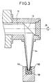
- Fig. 3 shows a construction view of a stop plug which cuts off the working gas at the gas nozzle of the work head.
- FIG. 4 shows a construction view of a stop valve which cuts off the working gas at the work head .
- FIG. 5 shows a perspective view of a conventional laser robot apparatus.
- FIG. 6 shows a detail construction of a work head portion of the conventional laser robot apparatus.
- FIG. 1 is a perspective view of a laser machining apparatus embodying the present invention.
- a laser oscillator 2 generates laser beam and a beam transmitting apparatus 3 transmits the laser beam generated in the laser oscillator 2 to a laser robot 1.
- the beam transmitting apparatus 3 is constructed of bend mirrors ( BM1, MB2) which change the beam direction, connected beam ducts which protect the human body from the laser beam, and support members (not shown) which support the beam ducts.
- a gas supplying inlet 31 is mounted upward of the beam transmitting apparatus 3 and supplies a working gas into the first of the connected beam ducts of the beam transmitting apparatus 3.
- a laser beam generated in the laser oscillator 2 passes through the beam duct and the bend mirrors in the laser robot and reaches the focus 15 of the workpiece after being concentrated using a parabolic minor.
- the present embodiment there are two different features compared with the conventional design.
- FIG. 3 One feature as seen in FIG. 3 is that there is no window in the beam ducts near the gas nozzle 14 of the laser robot.
- gas supplying inlet is mounted near the output of the laser oscillator 2 as seen in FIG. 2.
- all beam ducts are hermetically sealed between the laser oscillator and the robot head, including ducts in the laser robot 1.
- a gas supplying inlet 31 is mounted in the first duct near the laser outlet. The working gas is supplied from the gas supplying inlet 31 into the first beam duct 32, goes through the first beam duct 32 and all subsequent ducts including ducts in the laser robot 1, and is supplied to the work head portion 4.
- the fumes or dust are not able to go backward into the laser beam duct. As a result, fumes or dust can not adhere to the bend mirrors in the ducts and lens at the outlet of the laser oscillator 2.
- FIG. 2 shows a enlarged view of a gas supplying portion where the working gas is supplied into the laser beam duct.
- the beam ducts are cooled by fresh air purging.
- the working gas is supplied from the gas supplying inlet 31 and cools the beam ducts as the working gas flows in the beam duct 32 and the beam ducts in the laser robot 1.
- the working gas supplied from the gas supplying inlet 31 blows onto the workpiece through the gas nozzle 14 of the work head 4 and prevents the fumes and dust from entering into the gas nozzle 14. If the working gas must be flowing even through the laser robot machine is not working, the running cost is extremely expensive. Therefore it is necessary to stop the working gas while the laser robot machine is not working, in order to save costs.
- FIG. 3 shows a construction view of a stop plug 19 which cuts off the working gas at the gas nozzle 14 of the work head 4.
- a stop plug pedestal 192 In the construction of the stop plug 19 there is a stop plug pedestal 192 and a stop plug rubber 191.
- the working gas is stopped by the stop plug rubber 191 which forms a seal around the outside of the nozzle and the nozzle outlet and prevents the working gas from leaking outside.
- the stop plug may be located at a waiting point ( separated from the robot frame) of the gas nozzle 14 .
- FIG. 4 shows other construction view of a stop valve which cut off the working gas at the work head 4.
- the working gas is stopped at the stop valve 21 which is derived by the air cylinder 22.
- the stop valve 21 is pushed into the gas nozzle 14, the working gas is stopped from going out of the tip of the gas nozzle 14 to the workpiece.
- both of the apparatus shown in FIG. 3 and FIG. 4 are intended to stop the working gas at the tip of the gas nozzle 14.
- the stop valve 21 is mounted far from the tip of the gas nozzle 14, the machining rise time will be long because the air that enters the tip of the gas nozzle 14 must be evacuated.
- a pressure sensor 35 in FIG. 2 detects the increased pressure in the beam duct 32.
- a control apparatus 37 controls an electromagnetic valve 36 so that the working gas is stopped from being supplied when the pressure of the gas sensor 35 becomes more than a predetermined value.
- the control apparatus 37 is able to control the inner pressure of the beam ducts to be a little higher than the outside pressure by detecting the inner pressure using the pressure sensor 35.
- the above construction is able to prevent the fumes and dust from entering into the beam ducts.
Landscapes
- Physics & Mathematics (AREA)
- Engineering & Computer Science (AREA)
- Optics & Photonics (AREA)
- Plasma & Fusion (AREA)
- Mechanical Engineering (AREA)
- Fluid Mechanics (AREA)
- Robotics (AREA)
- Laser Beam Processing (AREA)
Claims (6)
- Appareil d'usinage à laser comprenant:- un oscillateur laser (2) pour produire un faisceau laser;- un robot à laser (1) ayant un éjecteur (14) pour usiner une pièce au moyen dudit faisceau laser;- un appareil de transmission de faisceau (3) afin de transmettre ledit faisceau laser entre une sortie dudit oscillateur laser (2) et une sortie dudit éjecteur (14) dudit robot à laser (1);dans lequel :- ledit appareil de transmission de faisceau (3) comporte un moyen de conduit (32) pour faisceau;- ledit moyen de conduit (32) pour faisceau, qui comprend au moins un conduit, s'étend entre une portion supérieure à l'oscillateur laser (2) et l'éjecteur (14) du robot à laser et est hermétiquement fermé sur sa longueur;caractérisé en ce que :- un orifice d'alimentation en gaz (31) est monté à ladite portion supérieure dudit moyen de conduit (32) pour faisceau;- ledit moyen de conduit (32) pour faisceau est ouvert intérieurement entre la sortie de l'oscillateur laser (2) et la sortie pour faisceau de l'éjecteur du robot à laser; et- seuls des moyens de lentille optique non-fenêtre sont fournis dans ledit moyen de conduit (32) pour faisceau.
- Appareil d'usinage à laser selon la revendication 1, comportant en outre :- un capteur de pression (35) pour détecter la pression dans ledit conduit pour faisceau;- une soupape de commande de gaz de travail (36) pour commander la fourniture en gaz de travail audit orifice d'alimentation en gaz (31); et- un appareil de commande (37) pour commander ladite soupape de commande de gaz de travail (36) de façon que la pression intérieure régnant dans le conduit pour faisceau soit supérieure à la pression extérieure en détectant ladite pression intérieure à l'aide dudit capteur de pression (35).
- Appareil d'usinage par laser selon la revendication 2, dans lequel ledit appareil de commande (37) commande la soupape de commande du gaz de travail (36) de façon que la fourniture dudit gaz de travail soit stoppée lorsque ladite pression intérieure du gaz de travail devient supérieure à une valeur prédéterminée.
- Appareil d'usinage par laser selon l'une des revendications 1 à 3, comportant en outre :- un moyen de bouchon d'arrêt (19) pour couper le gaz de travail à la pointe de l'éjecteur (14) du robot à laser.
- Appareil d'usinage par laser selon l'une des revendications 1 à 3, comportant en outre :- un moyen de soupape d'arrêt (21, 22) monté dans l'éjecteur (14) pour couper le gaz de travail à la pointe de l'éjecteur (14) du robot à laser.
- Appareil d'usinage par laser selon l'une des revendications 1 à 5, comportant en outre :- un moyen de panneau de dérivation de gaz (34) monté à l'intérieur dudit conduit pour faisceau afin de modifier l'écoulement du gaz de travail sans provoquer le changement de la direction du faisceau laser.
Applications Claiming Priority (2)
| Application Number | Priority Date | Filing Date | Title |
|---|---|---|---|
| JP162843/91 | 1991-07-03 | ||
| JP3162843A JP2591371B2 (ja) | 1991-07-03 | 1991-07-03 | レーザ加工装置 |
Publications (3)
| Publication Number | Publication Date |
|---|---|
| EP0521194A2 EP0521194A2 (fr) | 1993-01-07 |
| EP0521194A3 EP0521194A3 (en) | 1993-01-27 |
| EP0521194B1 true EP0521194B1 (fr) | 1995-03-29 |
Family
ID=15762302
Family Applications (1)
| Application Number | Title | Priority Date | Filing Date |
|---|---|---|---|
| EP91121352A Expired - Lifetime EP0521194B1 (fr) | 1991-07-03 | 1991-12-12 | Appareil d'usinage au laser pour souder et découper |
Country Status (4)
| Country | Link |
|---|---|
| US (1) | US5221823A (fr) |
| EP (1) | EP0521194B1 (fr) |
| JP (1) | JP2591371B2 (fr) |
| DE (1) | DE69108549T2 (fr) |
Families Citing this family (64)
| Publication number | Priority date | Publication date | Assignee | Title |
|---|---|---|---|---|
| US5744776A (en) * | 1989-07-14 | 1998-04-28 | Tip Engineering Group, Inc. | Apparatus and for laser preweakening an automotive trim cover for an air bag deployment opening |
| JPH0679484A (ja) * | 1992-07-14 | 1994-03-22 | Mitsubishi Electric Corp | レーザ溶接方法 |
| US5430270A (en) * | 1993-02-17 | 1995-07-04 | Electric Power Research Institute, Inc. | Method and apparatus for repairing damaged tubes |
| US5514849A (en) * | 1993-02-17 | 1996-05-07 | Electric Power Research Institute, Inc. | Rotating apparatus for repairing damaged tubes |
| FR2737311A1 (fr) * | 1995-07-25 | 1997-01-31 | Bm Ind | Dispositif de gestion de faisceau |
| US6153853A (en) * | 1996-12-25 | 2000-11-28 | Honda Giken Kogyo Kabushiki Kaisha | Laser beam welding apparatus |
| GB2326835B (en) * | 1996-12-25 | 1999-08-04 | Honda Motor Co Ltd | Laser beam welding apparatus |
| DE19734715A1 (de) | 1997-08-11 | 1999-02-25 | Lambda Physik Gmbh | Vorrichtung zum Spülen des Strahlenganges eines UV-Laserstrahles |
| US6381256B1 (en) | 1999-02-10 | 2002-04-30 | Lambda Physik Ag | Molecular fluorine laser with spectral linewidth of less than 1 pm |
| US6424666B1 (en) | 1999-06-23 | 2002-07-23 | Lambda Physik Ag | Line-narrowing module for high power laser |
| US6442182B1 (en) | 1999-02-12 | 2002-08-27 | Lambda Physik Ag | Device for on-line control of output power of vacuum-UV laser |
| US6795473B1 (en) | 1999-06-23 | 2004-09-21 | Lambda Physik Ag | Narrow band excimer laser with a prism-grating as line-narrowing optical element |
| US6426966B1 (en) | 1999-02-10 | 2002-07-30 | Lambda Physik Ag | Molecular fluorine (F2) laser with narrow spectral linewidth |
| US6490307B1 (en) | 1999-03-17 | 2002-12-03 | Lambda Physik Ag | Method and procedure to automatically stabilize excimer laser output parameters |
| US6421365B1 (en) | 1999-11-18 | 2002-07-16 | Lambda Physik Ag | Narrow band excimer or molecular fluorine laser having an output coupling interferometer |
| US6717973B2 (en) | 1999-02-10 | 2004-04-06 | Lambda Physik Ag | Wavelength and bandwidth monitor for excimer or molecular fluorine laser |
| US6965624B2 (en) * | 1999-03-17 | 2005-11-15 | Lambda Physik Ag | Laser gas replenishment method |
| US6678291B2 (en) | 1999-12-15 | 2004-01-13 | Lambda Physik Ag | Molecular fluorine laser |
| US6389052B2 (en) | 1999-03-17 | 2002-05-14 | Lambda Physik Ag | Laser gas replenishment method |
| US6463086B1 (en) | 1999-02-10 | 2002-10-08 | Lambda Physik Ag | Molecular fluorine laser with spectral linewidth of less than 1 pm |
| US6546037B2 (en) | 1999-02-10 | 2003-04-08 | Lambda Physik Ag | Molecular fluorine laser with spectral linewidth of less than 1 pm |
| US6327290B1 (en) | 1999-02-12 | 2001-12-04 | Lambda Physik Ag | Beam delivery system for molecular fluorine (F2) laser |
| US6700915B2 (en) | 1999-03-12 | 2004-03-02 | Lambda Physik Ag | Narrow band excimer laser with a resonator containing an optical element for making wavefront corrections |
| US6727731B1 (en) | 1999-03-12 | 2004-04-27 | Lambda Physik Ag | Energy control for an excimer or molecular fluorine laser |
| DE29907349U1 (de) | 1999-04-26 | 2000-07-06 | Lambda Physik Gesellschaft zur Herstellung von Lasern mbH, 37079 Göttingen | Laser zur Erzeugung schmalbandiger Strahlung |
| US6376798B1 (en) * | 1999-07-23 | 2002-04-23 | Lillbacka Jetair Oy | Laser cutting system |
| US6785316B1 (en) | 1999-08-17 | 2004-08-31 | Lambda Physik Ag | Excimer or molecular laser with optimized spectral purity |
| US6553050B1 (en) | 1999-11-18 | 2003-04-22 | Lambda Physik Ag | Narrow band excimer or molecular fluorine laser having an output coupling interferometer |
| US6529533B1 (en) | 1999-11-22 | 2003-03-04 | Lambda Physik Ag | Beam parameter monitoring unit for a molecular fluorine (F2) laser |
| US6603788B1 (en) | 1999-11-23 | 2003-08-05 | Lambda Physik Ag | Resonator for single line selection |
| US6795456B2 (en) | 1999-12-20 | 2004-09-21 | Lambda Physik Ag | 157 nm laser system and method for multi-layer semiconductor failure analysis |
| US6907058B2 (en) | 2000-01-25 | 2005-06-14 | Lambda Physik Ag | Energy monitor for molecular fluorine laser |
| US7075963B2 (en) | 2000-01-27 | 2006-07-11 | Lambda Physik Ag | Tunable laser with stabilized grating |
| US6735232B2 (en) | 2000-01-27 | 2004-05-11 | Lambda Physik Ag | Laser with versatile output energy |
| US6618403B2 (en) | 2000-03-16 | 2003-09-09 | Lambda Physik Ag | Method and apparatus for compensation of beam property drifts detected by measurement systems outside of an excimer laser |
| US6834066B2 (en) | 2000-04-18 | 2004-12-21 | Lambda Physik Ag | Stabilization technique for high repetition rate gas discharge lasers |
| US6862307B2 (en) * | 2000-05-15 | 2005-03-01 | Lambda Physik Ag | Electrical excitation circuit for a pulsed gas laser |
| US6577663B2 (en) | 2000-06-19 | 2003-06-10 | Lambda Physik Ag | Narrow bandwidth oscillator-amplifier system |
| US6603789B1 (en) | 2000-07-05 | 2003-08-05 | Lambda Physik Ag | Narrow band excimer or molecular fluorine laser with improved beam parameters |
| US6721345B2 (en) | 2000-07-14 | 2004-04-13 | Lambda Physik Ag | Electrostatic precipitator corona discharge ignition voltage probe for gas status detection and control system for gas discharge lasers |
| US6807205B1 (en) | 2000-07-14 | 2004-10-19 | Lambda Physik Ag | Precise monitor etalon calibration technique |
| US6801561B2 (en) | 2000-09-25 | 2004-10-05 | Lambda Physik Ag | Laser system and method for spectral narrowing through wavefront correction |
| US6747741B1 (en) | 2000-10-12 | 2004-06-08 | Lambda Physik Ag | Multiple-pass interferometric device |
| US6804327B2 (en) * | 2001-04-03 | 2004-10-12 | Lambda Physik Ag | Method and apparatus for generating high output power gas discharge based source of extreme ultraviolet radiation and/or soft x-rays |
| US7230964B2 (en) * | 2001-04-09 | 2007-06-12 | Cymer, Inc. | Lithography laser with beam delivery and beam pointing control |
| US6998620B2 (en) * | 2001-08-13 | 2006-02-14 | Lambda Physik Ag | Stable energy detector for extreme ultraviolet radiation detection |
| FR2843902A1 (fr) * | 2002-08-27 | 2004-03-05 | Usinor | Dispositif et procede de controle d'une operation de soudage, de rechargement ou d'usinage par faisceau laser d'une piece |
| US7379483B2 (en) | 2003-03-18 | 2008-05-27 | Loma Linda University Medical Center | Method and apparatus for material processing |
| US7060932B2 (en) | 2003-03-18 | 2006-06-13 | Loma Linda University Medical Center | Method and apparatus for material processing |
| US7038166B2 (en) | 2003-03-18 | 2006-05-02 | Loma Linda University Medical Center | Containment plenum for laser irradiation and removal of material from a surface of a structure |
| US7057134B2 (en) | 2003-03-18 | 2006-06-06 | Loma Linda University Medical Center | Laser manipulation system for controllably moving a laser head for irradiation and removal of material from a surface of a structure |
| US7286223B2 (en) | 2003-03-18 | 2007-10-23 | Loma Linda University Medical Center | Method and apparatus for detecting embedded rebar within an interaction region of a structure irradiated with laser light |
| US7880116B2 (en) * | 2003-03-18 | 2011-02-01 | Loma Linda University Medical Center | Laser head for irradiation and removal of material from a surface of a structure |
| JP4335154B2 (ja) | 2003-05-20 | 2009-09-30 | 三菱電機株式会社 | レーザ加工装置 |
| JP5020493B2 (ja) * | 2005-09-30 | 2012-09-05 | 日酸Tanaka株式会社 | レーザ加工機 |
| EP2133171B1 (fr) * | 2008-06-12 | 2012-08-08 | Trumpf Sachsen GmbH | Dispositif mécanique de traitement de pièces à usiner à l'aide d'un rayon laser |
| DE102010011207A1 (de) | 2010-03-09 | 2011-09-15 | B. Braun Melsungen Ag | Vorrichtung zum Schneiden von im Verbund vorliegenden miteinander verbundenen Kunststofferzeugnissen für den medizinischen Bereich |
| JP5930523B2 (ja) * | 2011-12-12 | 2016-06-08 | スターテクノ株式会社 | 樹脂成形品のレーザ光処理装置 |
| CN104174998B (zh) * | 2014-09-15 | 2016-09-14 | 江苏北人机器人系统股份有限公司 | 激光焊接系统 |
| US10493544B2 (en) * | 2016-02-05 | 2019-12-03 | Textron Innovations, Inc. | System and method for cutting composite materials |
| WO2017219264A1 (fr) * | 2016-06-22 | 2017-12-28 | 安徽中科镭泰激光科技有限公司 | Machine de traitement intelligente et usine de traitement intelligente |
| WO2018187671A1 (fr) | 2017-04-06 | 2018-10-11 | Elliott Gerard Wolf | Entrepôt automatisé |
| US11215552B2 (en) * | 2018-06-14 | 2022-01-04 | The Boeing Company | Apparatus and method for bond inspection with limited access |
| EP4590460A1 (fr) * | 2022-11-24 | 2025-07-30 | Max-Planck-Gesellschaft zur Förderung der Wissenschaften e.V. | Ligne de faisceau pour un faisceau laser, système laser et système tle |
Family Cites Families (8)
| Publication number | Priority date | Publication date | Assignee | Title |
|---|---|---|---|---|
| US4090572A (en) * | 1976-09-03 | 1978-05-23 | Nygaard-Welch-Rushing Partnership | Method and apparatus for laser treatment of geological formations |
| JPS6243605A (ja) * | 1985-08-21 | 1987-02-25 | Hitachi Cable Ltd | 炭酸ガスレ−ザ光用導波路 |
| IT206702Z2 (it) * | 1985-11-26 | 1987-10-01 | Comau Spa | Robot industriale per saldatura e taglio mediante fascio laser |
| US4695701A (en) * | 1986-03-17 | 1987-09-22 | Cincinnati Milacron Inc. | Laser wrist |
| US4808789A (en) * | 1987-02-04 | 1989-02-28 | Muncheryan Hrand M | Diode-pumped-laser instrumentation system |
| US4896015A (en) * | 1988-07-29 | 1990-01-23 | Refractive Laser Research & Development Program, Ltd. | Laser delivery system |
| US4892992A (en) * | 1988-11-03 | 1990-01-09 | Gmf Robotics Corporation | Industrial laser robot system |
| EP0435818B1 (fr) * | 1989-12-27 | 1994-06-15 | Sulzer Innotec Ag | Dispositif pour le soudage et/ou le recouvrement de pièce à usiner, base pour un tel dispositif ainsi que manipulateur pour la base d'un tel dispositif |
-
1991
- 1991-07-03 JP JP3162843A patent/JP2591371B2/ja not_active Expired - Lifetime
- 1991-12-12 DE DE69108549T patent/DE69108549T2/de not_active Expired - Fee Related
- 1991-12-12 EP EP91121352A patent/EP0521194B1/fr not_active Expired - Lifetime
-
1992
- 1992-01-17 US US07/821,810 patent/US5221823A/en not_active Expired - Fee Related
Also Published As
| Publication number | Publication date |
|---|---|
| EP0521194A2 (fr) | 1993-01-07 |
| DE69108549T2 (de) | 1995-10-05 |
| DE69108549D1 (de) | 1995-05-04 |
| US5221823A (en) | 1993-06-22 |
| JPH058079A (ja) | 1993-01-19 |
| JP2591371B2 (ja) | 1997-03-19 |
| EP0521194A3 (en) | 1993-01-27 |
Similar Documents
| Publication | Publication Date | Title |
|---|---|---|
| EP0521194B1 (fr) | Appareil d'usinage au laser pour souder et découper | |
| US11752572B2 (en) | Method and laser processing machining for laser welding a first and a second workpiece portion | |
| JP3138613B2 (ja) | レーザ加工装置 | |
| CA2040166C (fr) | Dispositif de positionnement automatique d'un appareil a souder pour le soudage bout a bout et methode connexe | |
| US7223935B2 (en) | Laser processing head | |
| US4652133A (en) | Vision system with environmental control | |
| WO2005049262A1 (fr) | Bras de soudure de laser a main a ecran de reflexion | |
| US5233202A (en) | Method of adjusting an optical path followed by a laser beam in a laser robot and an apparatus for carrying out the same | |
| JP3198830B2 (ja) | レーザ加工機 | |
| US20060191883A1 (en) | Laser processing | |
| JPH05506104A (ja) | レーザービーム等の平行ビームを配送するための装置 | |
| EP1091824A1 (fr) | Appareil permettant de determiner la position du point focal d'un systeme d'usinage au laser | |
| EP0769992A1 (fr) | Systeme optique de positionnement de faisceaux laser dans une position verticale ou angulaire | |
| JP4166450B2 (ja) | レーザ切断加工制御方法及び装置 | |
| JP2782247B2 (ja) | レーザ照射用トーチ | |
| JPH09248685A (ja) | レーザ加工装置 | |
| CA2028111A1 (fr) | Methode et appareil d'usinage par faisceau laser utilisant un reflecteur parabolique desaxe | |
| JPH05212570A (ja) | レーザロボットの付加軸装置 | |
| JPH10202385A (ja) | レーザ加工装置 | |
| US5058967A (en) | Apparatus for manipulating laser beams, particularly power laser beams for use by robots | |
| CN221361662U (zh) | 一种自动聚焦的可环绕式激光清洗装置 | |
| JPH07256478A (ja) | レーザ溶接ヘッド | |
| JPH0810978A (ja) | レーザ加工ヘッド | |
| JPH09141433A (ja) | 自動熱加工機のセンサ冷却装置 | |
| JPH08290283A (ja) | レーザビームを用いた加工装置 |
Legal Events
| Date | Code | Title | Description |
|---|---|---|---|
| PUAI | Public reference made under article 153(3) epc to a published international application that has entered the european phase |
Free format text: ORIGINAL CODE: 0009012 |
|
| PUAL | Search report despatched |
Free format text: ORIGINAL CODE: 0009013 |
|
| AK | Designated contracting states |
Kind code of ref document: A2 Designated state(s): DE GB IT |
|
| AK | Designated contracting states |
Kind code of ref document: A3 Designated state(s): DE GB IT |
|
| 17P | Request for examination filed |
Effective date: 19930310 |
|
| 17Q | First examination report despatched |
Effective date: 19930604 |
|
| GRAA | (expected) grant |
Free format text: ORIGINAL CODE: 0009210 |
|
| ITF | It: translation for a ep patent filed | ||
| AK | Designated contracting states |
Kind code of ref document: B1 Designated state(s): DE GB IT |
|
| REF | Corresponds to: |
Ref document number: 69108549 Country of ref document: DE Date of ref document: 19950504 |
|
| PGFP | Annual fee paid to national office [announced via postgrant information from national office to epo] |
Ref country code: GB Payment date: 19951204 Year of fee payment: 5 |
|
| PGFP | Annual fee paid to national office [announced via postgrant information from national office to epo] |
Ref country code: DE Payment date: 19951214 Year of fee payment: 5 |
|
| PLBE | No opposition filed within time limit |
Free format text: ORIGINAL CODE: 0009261 |
|
| STAA | Information on the status of an ep patent application or granted ep patent |
Free format text: STATUS: NO OPPOSITION FILED WITHIN TIME LIMIT |
|
| 26N | No opposition filed | ||
| PG25 | Lapsed in a contracting state [announced via postgrant information from national office to epo] |
Ref country code: GB Effective date: 19961212 |
|
| GBPC | Gb: european patent ceased through non-payment of renewal fee |
Effective date: 19961212 |
|
| PG25 | Lapsed in a contracting state [announced via postgrant information from national office to epo] |
Ref country code: DE Effective date: 19970902 |
|
| PG25 | Lapsed in a contracting state [announced via postgrant information from national office to epo] |
Ref country code: IT Free format text: LAPSE BECAUSE OF NON-PAYMENT OF DUE FEES;WARNING: LAPSES OF ITALIAN PATENTS WITH EFFECTIVE DATE BEFORE 2007 MAY HAVE OCCURRED AT ANY TIME BEFORE 2007. THE CORRECT EFFECTIVE DATE MAY BE DIFFERENT FROM THE ONE RECORDED. Effective date: 20051212 |