EP0521717A2 - Poignée de fermeture - Google Patents
Poignée de fermeture Download PDFInfo
- Publication number
- EP0521717A2 EP0521717A2 EP92306105A EP92306105A EP0521717A2 EP 0521717 A2 EP0521717 A2 EP 0521717A2 EP 92306105 A EP92306105 A EP 92306105A EP 92306105 A EP92306105 A EP 92306105A EP 0521717 A2 EP0521717 A2 EP 0521717A2
- Authority
- EP
- European Patent Office
- Prior art keywords
- handle
- plunger
- fixing plate
- closed position
- depressed
- Prior art date
- Legal status (The legal status is an assumption and is not a legal conclusion. Google has not performed a legal analysis and makes no representation as to the accuracy of the status listed.)
- Granted
Links
- 230000000994 depressogenic effect Effects 0.000 claims abstract description 22
- 230000006835 compression Effects 0.000 description 2
- 238000007906 compression Methods 0.000 description 2
- 230000007246 mechanism Effects 0.000 description 2
- 244000058871 Echinochloa crus-galli Species 0.000 description 1
- 241000773945 Trimusculidae Species 0.000 description 1
- 230000037431 insertion Effects 0.000 description 1
- 238000003780 insertion Methods 0.000 description 1
- 238000004519 manufacturing process Methods 0.000 description 1
- 239000002991 molded plastic Substances 0.000 description 1
- 230000000717 retained effect Effects 0.000 description 1
Images

Classifications
-
- E—FIXED CONSTRUCTIONS
- E05—LOCKS; KEYS; WINDOW OR DOOR FITTINGS; SAFES
- E05B—LOCKS; ACCESSORIES THEREFOR; HANDCUFFS
- E05B13/00—Devices preventing the key or the handle or both from being used
- E05B13/10—Devices preventing the key or the handle or both from being used formed by a lock arranged in the handle
- E05B13/106—Devices preventing the key or the handle or both from being used formed by a lock arranged in the handle for handles pivoted about an axis perpendicular to the wing
-
- E—FIXED CONSTRUCTIONS
- E05—LOCKS; KEYS; WINDOW OR DOOR FITTINGS; SAFES
- E05B—LOCKS; ACCESSORIES THEREFOR; HANDCUFFS
- E05B13/00—Devices preventing the key or the handle or both from being used
- E05B13/10—Devices preventing the key or the handle or both from being used formed by a lock arranged in the handle
- E05B13/105—Devices preventing the key or the handle or both from being used formed by a lock arranged in the handle the handle being a pushbutton
-
- E—FIXED CONSTRUCTIONS
- E05—LOCKS; KEYS; WINDOW OR DOOR FITTINGS; SAFES
- E05B—LOCKS; ACCESSORIES THEREFOR; HANDCUFFS
- E05B63/00—Locks or fastenings with special structural characteristics
- E05B63/24—Arrangements in which the fastening members which engage one another are mounted respectively on the wing and the frame and are both movable, e.g. for release by moving either of them
- E05B63/248—Arrangements in which the fastening members which engage one another are mounted respectively on the wing and the frame and are both movable, e.g. for release by moving either of them the striker being movable for latching, and pushed back by a member on the wing for unlatching, or vice versa
Definitions
- the invention relates to a locking handle for a door or window, the locking handle being of the kind comprising a fixing plate, a handle which is pivotally mounted on the fixing plate for movement between open and closed positions, and a catch which automatically engages when the handle is moved into the closed position to prevent subsequent movement of the handle to an open position until the catch is released.
- Such handles may be of the well known cockspur type or of the type used for operating espagnolette mechanisms and the like.
- such a locking handle is characterised in that the catch comprises a spring loaded plunger which is housed in the fixing plate and is arranged to project from the plate into a recess in the handle to prevent turning of the handle when the handle is in the closed position, the handle carries a spring loaded push button which can be depressed to push the plunger out of the recess to allow turning of the handle from the closed position, and a portion of the handle engages the plunger to hold it depressed within the fixing plate in all positions of the handle other than the closed position whether or not the push button is depressed.
- the portion of the handle which holds the plunger depressed when the handle is out of the closed position comprises a face of the handle which surrounds the recess and overlies the fixing plate when the handle is closed.
- the axes of the plunger and the push button are parallel, and are offset from each other when the handle is in the closed position so that the end of the push button which engages the plunger when the button is depressed only partially registers with the end of the plunger and has a portion disposed laterally outwards from the plunger.
- the push button may be provided with a locking cylinder which, when the button is not depressed, can be turned between a locked position in which depression of the button is prevented and an unlocked position in which depression of the button is permitted.
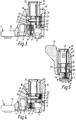
- the locking handle assembly comprises a fixing plate 1 of elongate rectangular shape having a recessed countersunk screw hole 2,3 near each end, and a substantially central aperture 4 with its axis parallel to the axes of the screw holes 2,3. Also provided in the upper face 5 of the fixing plate 1, between the central aperture 4 and the screw hole 3, is a rectangular recess 6 housing a correspondingly shaped hollow plunger 7 which is biased by a coiled compression spring 8 so as to project out of the recess 6 beyond the plane of the upper face 5 of the fixing plate, but which can be depressed fully into the recess 6 against the action of the spring 8.
- the locking handle assembly also comprises a handle 9 which is pivotally mounted on the fixing plate 1, the handle 9 having a body portion 10 provided with a boss 11 projecting from the underside 12 of the body portion and received rotatably in the aperture 4 of the fixing plate to pivotally mount the handle on the plate.
- the boss 11 is hollow for receiving a conventional square sectioned spindle (not shown) for driving an espagnolette mechanism, and conventional means (not shown), such as a circlip, is provided for preventing removal of the boss from the aperture 4.
- the handle 9 also includes a hand grip 13 which extends from the upper end of the body portion 10 at one side thereof in a direction substantially perpendicular to the pivot axis of the handle.
- the handle 9 is pivotable from a closed position shown in Figures 1,4 and 5 in which the undersurface 12 of the handle body 10 overlies the upper surface 5 of the fixing plate 1 and the hand grip 13 lies substantially parallel to the longitudinal axis of the fixing plate, and an open position, for example as illustrated in Figure 2, in which the handle 9 is displaced angularly from the closed position about the pivot axis defined by the boss 11 in the bore 4.
- the body portion 10 of the handle 9 is provided with a stop 14 which projects from the lower face 12 at one side thereof (in this example the same side as the hand grip 13) and which abuts the near side of the fixing plate 1 as shown in Figure 5 when the handle is in the closed position so that the handle can only be opened in one direction.
- the handle 9 can be opened through approximately 270° until the stop 14 comes into engagement with the opposite side of the fixing plate 1, the upper portion of the fixing plate at its end adjacent the screw hole 2 being cut away as indicated at 15 to accommodate the passage of the stop 14 during such movement of the handle.
- the body portion 10 of the handle is hollow to define an internal chamber 16 which is substantially closed at the underside 12 of the body portion by a moulded plastics plug 17.
- the plug 17 in fact forms an interface between the underside 12 of the body portion 10 and the upper surface 5 of the fixing plate 1, and is formed with a substantially rectangular recess 18 positioned so that when the handle is in the closed position the recess will register over the recess 6 in the fixing plate 1 whereby the plunger 7 will be able to enter the recess 18 under the action of its biasing spring 8 in order to prevent the handle from being turned from the closed position towards an open position.
- a push button 19 having a hollow shell portion 20 of substantially rectangular cross-section which extends through a correspondingly shaped opening at the upper end of the body portion 10 to project above the upper surface thereof.
- the push button 19 also comprises a cylindrical core 21 in the form of a key operated locking cylinder which is retained axially within the shell 20 and has its lower end projecting beyond the lower end of the shell into a substantially cylindrical passage 22 which extends through the plug 17 and intersects the recess 18.
- the axes of the recess 18 and the locking cylinder 21 are parallel but diagonally offset from each other so that approximately one sector of the passage cross-section overlaps one quadrant of the recess cross-section.
- the push button 19 is biased to a raised position as shown in Figure 1 by means of a coiled compression spring 23 housed within the chamber 16 and acting between the plug 17 and the lower end of the push button shell 20, a radially outwardly directed flange 24 at the lower end of the shell serving to limit the upward movement of the push button by engagement with the top of the chamber 16.
- the lower end of the locking cylinder 21 is retracted within the passage 22 to a position approximately level with the upper end of the recess 18, and the locking cylinder can be rotated, upon insertion of a key, between a locked position in which a radially projecting pin 25 carried by the locking cylinder engages a surface 26 of the plug 17 to prevent depression of the push button 19, and a released position in which the pin 25 is aligned with an axial slot 27 in the plug 17 to permit the button 19 to be depressed.
- the recess 18 moves out of registry with the recess 6, thus bringing a portion of the lower face of the plug 17 into engagement with the upper surface of the plunger 7 to hold the plunger in the depressed position within the recess 6, and the arrangement of the assembly is such that the plunger will be held down in this manner by a portion of the undersurface of the plug in all angular positions of the handle other than the closed position.
- the handle may be moved freely in the open condition without needing to hold the push button 19 depressed, and on return to the closed position, the plunger 7 will automatically move into engagement with the recess 18 to prevent further turning of the handle until the push button is once again depressed to push the plunger out of the recess 18.
Landscapes
- Lock And Its Accessories (AREA)
Applications Claiming Priority (2)
| Application Number | Priority Date | Filing Date | Title |
|---|---|---|---|
| GB9114193 | 1991-07-01 | ||
| GB9114193A GB2258003B (en) | 1991-07-01 | 1991-07-01 | Locking handle |
Publications (3)
| Publication Number | Publication Date |
|---|---|
| EP0521717A2 true EP0521717A2 (fr) | 1993-01-07 |
| EP0521717A3 EP0521717A3 (en) | 1993-03-03 |
| EP0521717B1 EP0521717B1 (fr) | 1995-09-13 |
Family
ID=10697629
Family Applications (1)
| Application Number | Title | Priority Date | Filing Date |
|---|---|---|---|
| EP19920306105 Expired - Lifetime EP0521717B1 (fr) | 1991-07-01 | 1992-07-01 | Poignée de fermeture |
Country Status (4)
| Country | Link |
|---|---|
| EP (1) | EP0521717B1 (fr) |
| DE (1) | DE69204767T2 (fr) |
| DK (1) | DK0521717T3 (fr) |
| GB (1) | GB2258003B (fr) |
Cited By (3)
| Publication number | Priority date | Publication date | Assignee | Title |
|---|---|---|---|---|
| FR2847552A1 (fr) * | 2002-11-27 | 2004-05-28 | Airbus France | Fenetre de cockpit d'aeronef |
| EP2362039A3 (fr) * | 2010-02-18 | 2017-03-08 | Fakro PP Spolka Z O.O. | Poignée avec levier rotatif et mécanisme de verrouillage de la rotation |
| CN108005476A (zh) * | 2017-12-21 | 2018-05-08 | 广东汇泰龙科技有限公司 | 一种防猫眼开锁的门锁 |
Families Citing this family (1)
| Publication number | Priority date | Publication date | Assignee | Title |
|---|---|---|---|---|
| GB9307841D0 (en) * | 1993-04-15 | 1993-06-02 | Wms Uk Ltd | An actuator handle assembly |
Family Cites Families (3)
| Publication number | Priority date | Publication date | Assignee | Title |
|---|---|---|---|---|
| JPS5929098Y2 (ja) * | 1976-08-24 | 1984-08-21 | ワイケイケイ株式会社 | ドアハンドル |
| EP0241245B2 (fr) * | 1986-04-07 | 1993-12-15 | Regent Lock Co. Ltd. | Poignée |
| FR2650323A1 (fr) * | 1989-07-27 | 1991-02-01 | Ronis Sa | Poignee rotative a pouvoir de deverrouillage |
-
1991
- 1991-07-01 GB GB9114193A patent/GB2258003B/en not_active Expired - Fee Related
-
1992
- 1992-07-01 DE DE1992604767 patent/DE69204767T2/de not_active Expired - Fee Related
- 1992-07-01 DK DK92306105T patent/DK0521717T3/da active
- 1992-07-01 EP EP19920306105 patent/EP0521717B1/fr not_active Expired - Lifetime
Cited By (5)
| Publication number | Priority date | Publication date | Assignee | Title |
|---|---|---|---|---|
| FR2847552A1 (fr) * | 2002-11-27 | 2004-05-28 | Airbus France | Fenetre de cockpit d'aeronef |
| EP1424278A1 (fr) * | 2002-11-27 | 2004-06-02 | Airbus France | Fenêtre de cockpit d'aéronef |
| US6883755B2 (en) | 2002-11-27 | 2005-04-26 | Airbus France | Aircraft cockpit window |
| EP2362039A3 (fr) * | 2010-02-18 | 2017-03-08 | Fakro PP Spolka Z O.O. | Poignée avec levier rotatif et mécanisme de verrouillage de la rotation |
| CN108005476A (zh) * | 2017-12-21 | 2018-05-08 | 广东汇泰龙科技有限公司 | 一种防猫眼开锁的门锁 |
Also Published As
| Publication number | Publication date |
|---|---|
| EP0521717B1 (fr) | 1995-09-13 |
| EP0521717A3 (en) | 1993-03-03 |
| DK0521717T3 (da) | 1995-11-13 |
| GB9114193D0 (en) | 1991-08-21 |
| DE69204767T2 (de) | 1996-05-02 |
| GB2258003B (en) | 1995-02-01 |
| DE69204767D1 (de) | 1995-10-19 |
| GB2258003A (en) | 1993-01-27 |
Similar Documents
| Publication | Publication Date | Title |
|---|---|---|
| US6854304B2 (en) | Paddle lock | |
| US7272964B2 (en) | Flush mounted latch | |
| US5784909A (en) | Control mechanism for tubular locks | |
| US6553796B2 (en) | Electrical panel lock with locking plug head | |
| US6341513B1 (en) | Two-in-one combination safe lock | |
| EP0535497B1 (fr) | Serrure perfectionnée avec dispositif d'ouverture en cas d'urgence | |
| KR900001944A (ko) | 피봇된 단일 새클 조립체를 갖춘 자물통 | |
| EP0521717B1 (fr) | Poignée de fermeture | |
| US5624141A (en) | Lock assembly for retracting a door latch | |
| EP0552033B1 (fr) | Poignée pour serrure | |
| GB2226359A (en) | Improvements in or relating to lockable handle assemblies | |
| US5713227A (en) | Lever activated dead-bolt lock | |
| JPS6070283A (ja) | 金庫扉等の施錠装置 | |
| GB2170548A (en) | Latch safety lock | |
| JPS5920522Y2 (ja) | 扉開閉及び施錠装置 | |
| WO1997033060A1 (fr) | Serrure complete | |
| JPH0611330Y2 (ja) | 押圧作動式平面ハンドル装置 | |
| JP3348048B2 (ja) | 引戸用密閉ロックハンドル装置 | |
| JPH0110841Y2 (fr) | ||
| JP2863138B2 (ja) | 裏側解錠機能付き扉用ロックハンドル装置 | |
| JPS5920524Y2 (ja) | 扉用ハンドル装置 | |
| KR100190590B1 (ko) | 도어개폐용 전자 자물쇠 | |
| JPS5920519Y2 (ja) | 扉用ハンドル装置 | |
| JP2500726Y2 (ja) | 電気錠 | |
| JPH086982Y2 (ja) | 扉用ロックハンドル |
Legal Events
| Date | Code | Title | Description |
|---|---|---|---|
| PUAI | Public reference made under article 153(3) epc to a published international application that has entered the european phase |
Free format text: ORIGINAL CODE: 0009012 |
|
| AK | Designated contracting states |
Kind code of ref document: A2 Designated state(s): AT BE CH DE DK ES FR GB GR IT LI LU MC NL PT SE |
|
| PUAL | Search report despatched |
Free format text: ORIGINAL CODE: 0009013 |
|
| AK | Designated contracting states |
Kind code of ref document: A3 Designated state(s): AT BE CH DE DK ES FR GB GR IT LI LU MC NL PT SE |
|
| RBV | Designated contracting states (corrected) |
Designated state(s): BE DE DK FR NL SE |
|
| 17P | Request for examination filed |
Effective date: 19930811 |
|
| 17Q | First examination report despatched |
Effective date: 19940610 |
|
| GRAA | (expected) grant |
Free format text: ORIGINAL CODE: 0009210 |
|
| AK | Designated contracting states |
Kind code of ref document: B1 Designated state(s): BE DE DK FR NL SE |
|
| REF | Corresponds to: |
Ref document number: 69204767 Country of ref document: DE Date of ref document: 19951019 |
|
| REG | Reference to a national code |
Ref country code: DK Ref legal event code: T3 |
|
| PG25 | Lapsed in a contracting state [announced via postgrant information from national office to epo] |
Ref country code: SE Effective date: 19951213 |
|
| ET | Fr: translation filed | ||
| PLBE | No opposition filed within time limit |
Free format text: ORIGINAL CODE: 0009261 |
|
| STAA | Information on the status of an ep patent application or granted ep patent |
Free format text: STATUS: NO OPPOSITION FILED WITHIN TIME LIMIT |
|
| 26N | No opposition filed | ||
| BECH | Be: change of holder |
Free format text: 961126 *CEGA FRAMEWARE LTD |
|
| REG | Reference to a national code |
Ref country code: FR Ref legal event code: TP Ref country code: FR Ref legal event code: CD |
|
| NLS | Nl: assignments of ep-patents |
Owner name: CEGO FRAMEWARE LIMITED |
|
| NLT1 | Nl: modifications of names registered in virtue of documents presented to the patent office pursuant to art. 16 a, paragraph 1 |
Owner name: PERMACELL FINESSE LIMITED |
|
| PGFP | Annual fee paid to national office [announced via postgrant information from national office to epo] |
Ref country code: FR Payment date: 19970709 Year of fee payment: 6 |
|
| PGFP | Annual fee paid to national office [announced via postgrant information from national office to epo] |
Ref country code: BE Payment date: 19970812 Year of fee payment: 6 |
|
| PGFP | Annual fee paid to national office [announced via postgrant information from national office to epo] |
Ref country code: DK Payment date: 19980713 Year of fee payment: 7 |
|
| PGFP | Annual fee paid to national office [announced via postgrant information from national office to epo] |
Ref country code: NL Payment date: 19980728 Year of fee payment: 7 |
|
| PG25 | Lapsed in a contracting state [announced via postgrant information from national office to epo] |
Ref country code: BE Free format text: LAPSE BECAUSE OF NON-PAYMENT OF DUE FEES Effective date: 19980731 |
|
| BERE | Be: lapsed |
Owner name: CEGA FRAMEWARE LTD Effective date: 19980731 |
|
| PG25 | Lapsed in a contracting state [announced via postgrant information from national office to epo] |
Ref country code: FR Free format text: LAPSE BECAUSE OF NON-PAYMENT OF DUE FEES Effective date: 19990331 |
|
| REG | Reference to a national code |
Ref country code: FR Ref legal event code: ST |
|
| PG25 | Lapsed in a contracting state [announced via postgrant information from national office to epo] |
Ref country code: DK Free format text: LAPSE BECAUSE OF NON-PAYMENT OF DUE FEES Effective date: 19990802 |
|
| PG25 | Lapsed in a contracting state [announced via postgrant information from national office to epo] |
Ref country code: NL Free format text: LAPSE BECAUSE OF NON-PAYMENT OF DUE FEES Effective date: 20000201 |
|
| REG | Reference to a national code |
Ref country code: DK Ref legal event code: EBP |
|
| NLV4 | Nl: lapsed or anulled due to non-payment of the annual fee |
Effective date: 20000201 |
|
| PGFP | Annual fee paid to national office [announced via postgrant information from national office to epo] |
Ref country code: DE Payment date: 20010625 Year of fee payment: 10 |
|
| PG25 | Lapsed in a contracting state [announced via postgrant information from national office to epo] |
Ref country code: DE Free format text: LAPSE BECAUSE OF NON-PAYMENT OF DUE FEES Effective date: 20030201 |