EP0522193A1 - Réseau de commutation numérique - Google Patents
Réseau de commutation numérique Download PDFInfo
- Publication number
- EP0522193A1 EP0522193A1 EP91111578A EP91111578A EP0522193A1 EP 0522193 A1 EP0522193 A1 EP 0522193A1 EP 91111578 A EP91111578 A EP 91111578A EP 91111578 A EP91111578 A EP 91111578A EP 0522193 A1 EP0522193 A1 EP 0522193A1
- Authority
- EP
- European Patent Office
- Prior art keywords
- transmission
- coupling module
- receiving
- transmission links
- receiving unit
- Prior art date
- Legal status (The legal status is an assumption and is not a legal conclusion. Google has not performed a legal analysis and makes no representation as to the accuracy of the status listed.)
- Granted
Links
- 230000005540 biological transmission Effects 0.000 claims abstract description 51
- 230000008878 coupling Effects 0.000 claims description 20
- 238000010168 coupling process Methods 0.000 claims description 20
- 238000005859 coupling reaction Methods 0.000 claims description 20
- 230000015654 memory Effects 0.000 claims description 10
- 238000012806 monitoring device Methods 0.000 claims description 4
- 230000000694 effects Effects 0.000 claims description 2
- 102100023708 Coiled-coil domain-containing protein 80 Human genes 0.000 description 2
- 101100154842 Danio rerio twsg1b gene Proteins 0.000 description 2
- 101000978383 Homo sapiens Coiled-coil domain-containing protein 80 Proteins 0.000 description 2
- 238000000034 method Methods 0.000 description 2
- 238000012432 intermediate storage Methods 0.000 description 1
- 230000001360 synchronised effect Effects 0.000 description 1
Images
Classifications
-
- H—ELECTRICITY
- H04—ELECTRIC COMMUNICATION TECHNIQUE
- H04M—TELEPHONIC COMMUNICATION
- H04M3/00—Automatic or semi-automatic exchanges
- H04M3/22—Arrangements for supervision, monitoring or testing
- H04M3/24—Arrangements for supervision, monitoring or testing with provision for checking the normal operation
- H04M3/244—Arrangements for supervision, monitoring or testing with provision for checking the normal operation for multiplex systems
-
- H—ELECTRICITY
- H04—ELECTRIC COMMUNICATION TECHNIQUE
- H04Q—SELECTING
- H04Q11/00—Selecting arrangements for multiplex systems
- H04Q11/04—Selecting arrangements for multiplex systems for time-division multiplexing
Definitions
- the invention relates to a digital switching network of a switching system according to the preamble of claim 1.
- time steps and room steps are combined in separately configurable switching modules (time switching modules and room switching modules).
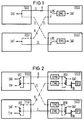
- the coupling modules are a time coupling module and a space coupling module, which are each doubled, ie are composed of two identical time coupling module halves TSG0 and TSG1 and two identical space coupling module halves SSG0 and SSG1.
- the two coupling modules shown are connected to one another by transmission links ZL.
- the transmission paths ZL shown in FIG. 1 for the transmission of a data stream DAT relate only to one transmission direction, namely from the time switching module to the space switching module.
- the transmission paths for the reverse transmission direction, namely from the space switching module to the time switching module are not shown.
- a transmission link comprises at least one multiplex line, each with a plurality of transmission channels.
- Each coupling module half contains, for the connection to an adjacent coupling module, a transmission and reception unit, not shown, which is connected to the corresponding transmission and reception units of the two coupling module halves of a coupling module of the adjacent switching network stage by a respective transmission path ZL, so that a reception unit has two inputs and a transmitter unit has two outputs each for the transmission links connected to it.
- the data stream DAT is divided among the two outputs and thus to both neighboring coupling module module halves sent.
- the receiving unit includes, inter alia, a receiving switch RS for switching between the two transmission links and a receiving buffer memory EMU for temporarily storing the received data DAT, and for carrying out frame synchronization.
- a receiving switch RS for switching between the two transmission links
- a receiving buffer memory EMU for temporarily storing the received data DAT, and for carrying out frame synchronization.
- One of the two transmission links connected to a receiving unit or transmitting unit is operated in each case as an active transmission link and the other as a passive, ie redundant transmission link, which is shown in FIG. 1 by a broken line.
- the mode of operation (configuration) of the transmission links includes determined by the position of the reception switch RS.
- the mode of operation (reconfiguration) of the transmission links is changed either for test purposes or in the case of certain failure constellations. Falls e.g. the time coupling module half TSG0 off, then a reconfiguration takes place, in which the reception switch RS of the room coupling module half SSG0 is switched. If the space switching module half SSG1 also fails in this situation, the reception switch in the time switching module half TSG1 is also switched over for the reverse transmission direction, not shown.
- the invention has for its object to avoid the disadvantages mentioned.
- the transmission unit of a coupling module half contains a changeover device, which is implemented in the form of a double transmission switch UST.
- the double transmission switch has the effect that the data stream DAT to be transmitted is only switched through to one of the two outputs. The consequence of this is that no data stream is transmitted on the passive transmission link and thus ensures a clear data transmission, ie double reception of information is avoided.
- the double transmitter switch also enables a test pattern current TM to be fed into the passive transmission path.
- the receiving unit contains a separate receiving memory EMU for each transmission link.
- a switchover device in the form of a double reception switch USR is arranged behind the two reception memories.
- the double reception switch serves on the one hand to change the mode of operation of the transmission link and on the other hand to hide the test pattern current to a monitoring device SFG. Since a frame synchronization takes place in the reception memories in addition to intermediate storage, the double reception switch performs a complete synchronous changeover during a changeover process.
- the SFG monitoring device is used to monitor the passive transmission links and has access to the receive memory of the passive transmission links via a test bus TB. Switching the mode of operation of the transmission links for test purposes is therefore superfluous.
- a test of the passive transmission links between the switching modules of a switching network can be initiated, for example, by an incentive from the central control of the switching system. Thereupon test pattern currents are fed into the passive transmission paths via the transmission units. After synchronization to the test pattern stream, the test patterns can be received and evaluated individually by the monitoring device in the reception memories of the corresponding reception units. In the event of an error, a corresponding error message can be sent to the central control of the switching system.
Landscapes
- Engineering & Computer Science (AREA)
- Signal Processing (AREA)
- Computer Networks & Wireless Communication (AREA)
- Detection And Prevention Of Errors In Transmission (AREA)
- Maintenance And Management Of Digital Transmission (AREA)
- Communication Control (AREA)
- Use Of Switch Circuits For Exchanges And Methods Of Control Of Multiplex Exchanges (AREA)
- Mobile Radio Communication Systems (AREA)
- Time-Division Multiplex Systems (AREA)
- Data Exchanges In Wide-Area Networks (AREA)
Priority Applications (5)
| Application Number | Priority Date | Filing Date | Title |
|---|---|---|---|
| DE59108705T DE59108705D1 (de) | 1991-07-11 | 1991-07-11 | Digitales Koppelnetz |
| AT91111578T ATE153209T1 (de) | 1991-07-11 | 1991-07-11 | Digitales koppelnetz |
| EP91111578A EP0522193B1 (fr) | 1991-07-11 | 1991-07-11 | Réseau de couplage numérique |
| ES91111578T ES2102374T3 (es) | 1991-07-11 | 1991-07-11 | Red de acoplamiento digital. |
| GR970401752T GR3024101T3 (en) | 1991-07-11 | 1997-07-15 | Digital coupling network |
Applications Claiming Priority (1)
| Application Number | Priority Date | Filing Date | Title |
|---|---|---|---|
| EP91111578A EP0522193B1 (fr) | 1991-07-11 | 1991-07-11 | Réseau de couplage numérique |
Publications (2)
| Publication Number | Publication Date |
|---|---|
| EP0522193A1 true EP0522193A1 (fr) | 1993-01-13 |
| EP0522193B1 EP0522193B1 (fr) | 1997-05-14 |
Family
ID=8206924
Family Applications (1)
| Application Number | Title | Priority Date | Filing Date |
|---|---|---|---|
| EP91111578A Expired - Lifetime EP0522193B1 (fr) | 1991-07-11 | 1991-07-11 | Réseau de couplage numérique |
Country Status (5)
| Country | Link |
|---|---|
| EP (1) | EP0522193B1 (fr) |
| AT (1) | ATE153209T1 (fr) |
| DE (1) | DE59108705D1 (fr) |
| ES (1) | ES2102374T3 (fr) |
| GR (1) | GR3024101T3 (fr) |
Cited By (2)
| Publication number | Priority date | Publication date | Assignee | Title |
|---|---|---|---|---|
| WO1997020436A3 (fr) * | 1995-11-29 | 1997-07-31 | Ericsson Telefon Ab L M | Procede et appareil pour la verification de la connexion entre elements de circuits |
| EP0794626A3 (fr) * | 1996-03-06 | 2000-04-26 | Nokia Networks Oy | Réseau de télécommunication HNS (SDH) |
Citations (4)
| Publication number | Priority date | Publication date | Assignee | Title |
|---|---|---|---|---|
| DE2540577A1 (de) * | 1975-09-11 | 1977-03-17 | Siemens Ag | Pcm-zeitmultiplexkoppelfeld |
| GB2014018A (en) * | 1978-02-01 | 1979-08-15 | Nippon Telegraph & Telephone | Time division telephone switching systems |
| DE2910236A1 (de) * | 1979-03-15 | 1980-09-25 | Siemens Ag | Verfahren zur pruefung von elektronischen baueinheiten einer vermittlungsanlage, insbesondere fernsprechanlage |
| EP0360065A1 (fr) * | 1988-09-23 | 1990-03-28 | Siemens Aktiengesellschaft | Procédé de contrôle de centraux de télécommunication, en particulier centraux téléphoniques MIC à division dans le temps avec plusieurs réseaux de commutation distribués connectés à un réseau de commutation central |
-
1991
- 1991-07-11 EP EP91111578A patent/EP0522193B1/fr not_active Expired - Lifetime
- 1991-07-11 AT AT91111578T patent/ATE153209T1/de not_active IP Right Cessation
- 1991-07-11 DE DE59108705T patent/DE59108705D1/de not_active Expired - Fee Related
- 1991-07-11 ES ES91111578T patent/ES2102374T3/es not_active Expired - Lifetime
-
1997
- 1997-07-15 GR GR970401752T patent/GR3024101T3/el unknown
Patent Citations (4)
| Publication number | Priority date | Publication date | Assignee | Title |
|---|---|---|---|---|
| DE2540577A1 (de) * | 1975-09-11 | 1977-03-17 | Siemens Ag | Pcm-zeitmultiplexkoppelfeld |
| GB2014018A (en) * | 1978-02-01 | 1979-08-15 | Nippon Telegraph & Telephone | Time division telephone switching systems |
| DE2910236A1 (de) * | 1979-03-15 | 1980-09-25 | Siemens Ag | Verfahren zur pruefung von elektronischen baueinheiten einer vermittlungsanlage, insbesondere fernsprechanlage |
| EP0360065A1 (fr) * | 1988-09-23 | 1990-03-28 | Siemens Aktiengesellschaft | Procédé de contrôle de centraux de télécommunication, en particulier centraux téléphoniques MIC à division dans le temps avec plusieurs réseaux de commutation distribués connectés à un réseau de commutation central |
Cited By (3)
| Publication number | Priority date | Publication date | Assignee | Title |
|---|---|---|---|---|
| WO1997020436A3 (fr) * | 1995-11-29 | 1997-07-31 | Ericsson Telefon Ab L M | Procede et appareil pour la verification de la connexion entre elements de circuits |
| US5937032A (en) * | 1995-11-29 | 1999-08-10 | Telefonaktiebolaget L M | Testing method and apparatus for verifying correct connection of curcuit elements |
| EP0794626A3 (fr) * | 1996-03-06 | 2000-04-26 | Nokia Networks Oy | Réseau de télécommunication HNS (SDH) |
Also Published As
| Publication number | Publication date |
|---|---|
| EP0522193B1 (fr) | 1997-05-14 |
| DE59108705D1 (de) | 1997-06-19 |
| GR3024101T3 (en) | 1997-10-31 |
| ES2102374T3 (es) | 1997-08-01 |
| ATE153209T1 (de) | 1997-05-15 |
Similar Documents
| Publication | Publication Date | Title |
|---|---|---|
| DE2362010C2 (de) | Verfahren zur Fehlerüberwachung und Fehleralarmauslösung in einem Mikrowellen-Übertragungsnetz sowie Anordnung zur Durchführung des Verfahrens | |
| EP0384936A1 (fr) | Procédé et dispositif pour transmettre des paquets d'information provenant de lignes d'entrée via un dispositif à communication de paquets | |
| EP1066702B1 (fr) | Unite de commutation du bus maitre | |
| EP0503284B1 (fr) | Dispositif de couplage à auto-acheminement à trois étages avec au moins une structure dédoublée | |
| DE69532592T2 (de) | Reorganisationsvorrichtung zur neugruppierung von telekommunikationssignalen | |
| EP0381011A2 (fr) | Réseau de transmission avec des noeuds commutables | |
| DE3850138T2 (de) | Verfahren und Einrichtung zur Fehlerdetektion in einem Ringnetzdatenübertragungssystem. | |
| EP0512141A1 (fr) | Procédé pour commuter un flux de données du type ATM à grand débit dans un réseau de commutation à débit faible | |
| EP0683583B1 (fr) | Procédé et circuit pour réacheminer sans erreurs le flux de cellules d'information à travers une voie alternative | |
| DE69317507T2 (de) | Fehlertolerantes Rechnersystem mit einem in jedem Prozessormodul vorgesehenen Fehlerdetektor | |
| EP0682422A2 (fr) | Méthode et dispositif pour synchroniser un train de cellules transmis avec redondance | |
| EP0448734A1 (fr) | Disposition de circuit pour tester par routine l'interface entre les groupes de transmission et le réseau de commutation d'un central de télécommunication à MIC | |
| DE2647738C2 (de) | Fehlerortungs-Verfahren für schleifenförmige Nachrichtenübertragungsanlagen und Anordnung zur Durchführung dieses Verfahrens | |
| AT404656B (de) | Leitungsredundantes feldbussystem, vorzugsweise mit ringtopologie | |
| DE69433313T2 (de) | Multi-Master Überwachungssystem | |
| EP0522193B1 (fr) | Réseau de couplage numérique | |
| DE4242438C2 (de) | Vorrichtung zur Ausnutzung der Redundanz bei Datenringen in Doppelringtopologie | |
| EP1050814B1 (fr) | Système tolérant de fautes utilisant un algorithme byzantine | |
| EP0426739B1 (fr) | Procede d'acquisition d'informations concernant le reseau dans un reseau de transmission numerique et un tel reseau de transmission numerique | |
| EP0732828B1 (fr) | Réseau de communication optimisé en redondance pour la transmission de signaux de données | |
| DE4041235C1 (en) | Double ring bus system - has two buses which normally operate in parallel or are cross-coupled for testing to identify failure | |
| DE2459758A1 (de) | Verbindungseinheit zur exklusiven verbindung von zwei zweigleitungen in einer nachrichtenanlage | |
| DE4243266C2 (de) | Verfahren zum Betrieb einer Kommunikationsschaltvorrichtung | |
| DE19513316A1 (de) | Segmentierbares Ethernet-Bussystem | |
| DE19513315C2 (de) | Segmentierbares Ethernet-Bussystem |
Legal Events
| Date | Code | Title | Description |
|---|---|---|---|
| PUAI | Public reference made under article 153(3) epc to a published international application that has entered the european phase |
Free format text: ORIGINAL CODE: 0009012 |
|
| AK | Designated contracting states |
Kind code of ref document: A1 Designated state(s): AT BE CH DE DK ES FR GB GR IT LI LU NL SE |
|
| RBV | Designated contracting states (corrected) |
Designated state(s): AT BE CH DE ES FR GB GR IT LI LU NL SE |
|
| 17P | Request for examination filed |
Effective date: 19930422 |
|
| 17Q | First examination report despatched |
Effective date: 19950731 |
|
| GRAG | Despatch of communication of intention to grant |
Free format text: ORIGINAL CODE: EPIDOS AGRA |
|
| GRAH | Despatch of communication of intention to grant a patent |
Free format text: ORIGINAL CODE: EPIDOS IGRA |
|
| GRAH | Despatch of communication of intention to grant a patent |
Free format text: ORIGINAL CODE: EPIDOS IGRA |
|
| GRAA | (expected) grant |
Free format text: ORIGINAL CODE: 0009210 |
|
| AK | Designated contracting states |
Kind code of ref document: B1 Designated state(s): AT BE CH DE ES FR GB GR IT LI LU NL SE |
|
| REF | Corresponds to: |
Ref document number: 153209 Country of ref document: AT Date of ref document: 19970515 Kind code of ref document: T |
|
| REG | Reference to a national code |
Ref country code: CH Ref legal event code: NV Representative=s name: SIEMENS SCHWEIZ AG Ref country code: CH Ref legal event code: EP |
|
| REF | Corresponds to: |
Ref document number: 59108705 Country of ref document: DE Date of ref document: 19970619 |
|
| ET | Fr: translation filed | ||
| REG | Reference to a national code |
Ref country code: ES Ref legal event code: FG2A Ref document number: 2102374 Country of ref document: ES Kind code of ref document: T3 |
|
| GBT | Gb: translation of ep patent filed (gb section 77(6)(a)/1977) |
Effective date: 19970724 |
|
| REG | Reference to a national code |
Ref country code: GR Ref legal event code: FG4A Free format text: 3024101 |
|
| PLBE | No opposition filed within time limit |
Free format text: ORIGINAL CODE: 0009261 |
|
| STAA | Information on the status of an ep patent application or granted ep patent |
Free format text: STATUS: NO OPPOSITION FILED WITHIN TIME LIMIT |
|
| 26N | No opposition filed | ||
| PGFP | Annual fee paid to national office [announced via postgrant information from national office to epo] |
Ref country code: GB Payment date: 19980623 Year of fee payment: 8 |
|
| PGFP | Annual fee paid to national office [announced via postgrant information from national office to epo] |
Ref country code: ES Payment date: 19980707 Year of fee payment: 8 |
|
| PGFP | Annual fee paid to national office [announced via postgrant information from national office to epo] |
Ref country code: BE Payment date: 19980709 Year of fee payment: 8 |
|
| PGFP | Annual fee paid to national office [announced via postgrant information from national office to epo] |
Ref country code: LU Payment date: 19980727 Year of fee payment: 8 |
|
| PGFP | Annual fee paid to national office [announced via postgrant information from national office to epo] |
Ref country code: NL Payment date: 19980728 Year of fee payment: 8 |
|
| PGFP | Annual fee paid to national office [announced via postgrant information from national office to epo] |
Ref country code: CH Payment date: 19981102 Year of fee payment: 8 |
|
| PGFP | Annual fee paid to national office [announced via postgrant information from national office to epo] |
Ref country code: AT Payment date: 19990616 Year of fee payment: 9 |
|
| PGFP | Annual fee paid to national office [announced via postgrant information from national office to epo] |
Ref country code: GR Payment date: 19990630 Year of fee payment: 9 |
|
| PG25 | Lapsed in a contracting state [announced via postgrant information from national office to epo] |
Ref country code: LU Free format text: LAPSE BECAUSE OF NON-PAYMENT OF DUE FEES Effective date: 19990711 Ref country code: GB Free format text: LAPSE BECAUSE OF NON-PAYMENT OF DUE FEES Effective date: 19990711 |
|
| PG25 | Lapsed in a contracting state [announced via postgrant information from national office to epo] |
Ref country code: ES Free format text: LAPSE BECAUSE OF NON-PAYMENT OF DUE FEES Effective date: 19990712 |
|
| PG25 | Lapsed in a contracting state [announced via postgrant information from national office to epo] |
Ref country code: LI Free format text: LAPSE BECAUSE OF NON-PAYMENT OF DUE FEES Effective date: 19990731 Ref country code: CH Free format text: LAPSE BECAUSE OF NON-PAYMENT OF DUE FEES Effective date: 19990731 Ref country code: BE Free format text: LAPSE BECAUSE OF NON-PAYMENT OF DUE FEES Effective date: 19990731 |
|
| BERE | Be: lapsed |
Owner name: SIEMENS A.G. Effective date: 19990731 |
|
| PG25 | Lapsed in a contracting state [announced via postgrant information from national office to epo] |
Ref country code: NL Free format text: LAPSE BECAUSE OF NON-PAYMENT OF DUE FEES Effective date: 20000201 |
|
| GBPC | Gb: european patent ceased through non-payment of renewal fee |
Effective date: 19990711 |
|
| REG | Reference to a national code |
Ref country code: CH Ref legal event code: PL |
|
| NLV4 | Nl: lapsed or anulled due to non-payment of the annual fee |
Effective date: 20000201 |
|
| PG25 | Lapsed in a contracting state [announced via postgrant information from national office to epo] |
Ref country code: AT Free format text: LAPSE BECAUSE OF NON-PAYMENT OF DUE FEES Effective date: 20000711 |
|
| PG25 | Lapsed in a contracting state [announced via postgrant information from national office to epo] |
Ref country code: GR Free format text: LAPSE BECAUSE OF NON-PAYMENT OF DUE FEES Effective date: 20000731 |
|
| PGFP | Annual fee paid to national office [announced via postgrant information from national office to epo] |
Ref country code: DE Payment date: 20010919 Year of fee payment: 11 |
|
| REG | Reference to a national code |
Ref country code: ES Ref legal event code: FD2A Effective date: 20020603 |
|
| PGFP | Annual fee paid to national office [announced via postgrant information from national office to epo] |
Ref country code: SE Payment date: 20020724 Year of fee payment: 12 |
|
| PGFP | Annual fee paid to national office [announced via postgrant information from national office to epo] |
Ref country code: FR Payment date: 20020726 Year of fee payment: 12 |
|
| PG25 | Lapsed in a contracting state [announced via postgrant information from national office to epo] |
Ref country code: DE Free format text: LAPSE BECAUSE OF NON-PAYMENT OF DUE FEES Effective date: 20030201 |
|
| PG25 | Lapsed in a contracting state [announced via postgrant information from national office to epo] |
Ref country code: SE Free format text: LAPSE BECAUSE OF NON-PAYMENT OF DUE FEES Effective date: 20030712 |
|
| EUG | Se: european patent has lapsed | ||
| PG25 | Lapsed in a contracting state [announced via postgrant information from national office to epo] |
Ref country code: FR Free format text: LAPSE BECAUSE OF NON-PAYMENT OF DUE FEES Effective date: 20040331 |
|
| REG | Reference to a national code |
Ref country code: FR Ref legal event code: ST |
|
| PG25 | Lapsed in a contracting state [announced via postgrant information from national office to epo] |
Ref country code: IT Free format text: LAPSE BECAUSE OF NON-PAYMENT OF DUE FEES;WARNING: LAPSES OF ITALIAN PATENTS WITH EFFECTIVE DATE BEFORE 2007 MAY HAVE OCCURRED AT ANY TIME BEFORE 2007. THE CORRECT EFFECTIVE DATE MAY BE DIFFERENT FROM THE ONE RECORDED. Effective date: 20050711 |