EP0381011A2 - Réseau de transmission avec des noeuds commutables - Google Patents
Réseau de transmission avec des noeuds commutables Download PDFInfo
- Publication number
- EP0381011A2 EP0381011A2 EP19900101276 EP90101276A EP0381011A2 EP 0381011 A2 EP0381011 A2 EP 0381011A2 EP 19900101276 EP19900101276 EP 19900101276 EP 90101276 A EP90101276 A EP 90101276A EP 0381011 A2 EP0381011 A2 EP 0381011A2
- Authority
- EP
- European Patent Office
- Prior art keywords
- network node
- digital signal
- identifier
- network
- connection
- Prior art date
- Legal status (The legal status is an assumption and is not a legal conclusion. Google has not performed a legal analysis and makes no representation as to the accuracy of the status listed.)
- Withdrawn
Links
Images
Classifications
-
- H—ELECTRICITY
- H04—ELECTRIC COMMUNICATION TECHNIQUE
- H04Q—SELECTING
- H04Q3/00—Selecting arrangements
- H04Q3/0016—Arrangements providing connection between exchanges
Definitions
- the invention relates to a transmission network according to the preamble of patent claim 1.
- a transmission network is known from EP-A1 214 398.
- an identifier is inserted into the pulse frame of the digital signal to be transmitted at the start of each digital signal connection. This number identifies the source of the digital signal after consecutive numbering.
- a central computer detects the identifiers received in the individual network nodes and is thus able to monitor and control the network (at least with regard to the multiplex hierarchy of the digital signals used).
- the invention has for its object to provide a transmission network of the type mentioned, in which the switching of digital signal connections are carried out electronically controlled even in a setup phase of the network, in which a central network management is not yet available, or in the event of a failure of the central computer can.
- An advantage of the method described above lies primarily in the fact that it enables independent network management without complex data exchange from network nodes to network nodes. In particular, a quick substitute switching is possible because there is no need to go through several communication levels for a central or regional network management.
- the transmission of a static identifier - the identifier becomes a digital signal connection once at the beginning formed and only read and passed in the course of the connection - and the transmission method used make it possible to evaluate the identifier at the ports without the corresponding modules having to be provided with processors.
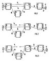
- the transmission network has network nodes A, B, C and D, which are each provided with ports 1 to 6. These ports 1 to 6 are both signal inputs and outputs: the data signal connection is usually bidirectional.
- the network nodes A to D are connected to one another and to the devices 11 and 12 by lines 13 to 22.
- To set up a new connection corresponding switching orders are given to all network nodes involved. This can be done in the usual way, for example via an operating station, or via a network management computer if it is in operation.
- network node A receives the order to connect port 2 to port 4, network node B the order to connect port 1 to port 5 and network node C the order to connect port 3 to port 6 .
- the connection is only carried out when a digital signal with a known frame structure is to be transmitted. If, on the other hand, a digital signal with an unknown frame structure is to be switched, the switching is not yet carried out in the end network nodes A and C, but the switching order is only stored in advance.
- one of the two end network nodes of the connection inserts an identifier into the digital signal to be sent from it to the other end network node.
- This end network node (for example A) is the so-called master network node of the connection.
- a bit indicates whether the end network node sending the identifier is the master network node of the connection or not.
- the identifier inserted into a digital signal has the following composition: [Source node, at port] [Destination node, from port] 1 if the source node of the digital signal is the master network node of the connection, or [Source node, at port] [Destination node, ab-port] 0, if the destination node of the digital signal is the master network node of the connection, where the source node is the end node that sends the digital signal to the other end node of the connection, the destination node, and the port of the source node or "to port” and "from port” Target node is designated at which the digital signal arrives at the source node or leaves the destination node.
- [A, 2] [C, 6] 1 the identifier for the digital signal to be transmitted from A to C of connection 11-12 according to FIG. 1 if A is the master node of the connection, and [C, 6] [A, 2] 0 the identifier for the digital signal to be transmitted in the opposite direction.
- the identifier also includes an information byte for the transmission of further information.
- the identifiers are transmitted from end network nodes to end network nodes.
- Each intermediate network node receiving an identifier forwards the received identifier to the next one in the course of the connection switched in it Connection in the direction of the next network node.
- Each of the network nodes involved in a connection checks the identifiers received on its ports to determine whether the identifiers match the connections switched in the network node.
- the network node A in which the input port 2 is connected to the output port 4 and which transmits the identifier [A, 2] [C, 6] 1 at port 4, checks the identifier received at port 4. If this contains the number of the destination network node, ie if it contains [C, 6] [A, 2] 0, network node A has the information that the connection is switched correctly.
- an affected network node is able to carry out an equivalent circuit on the basis of information that it has from the constant checking of received identifiers.
- lines are usually kept free in a digital transmission network so that they can be used as replacement connecting lines and downtimes after interruptions can be kept as short as possible.
- the network nodes can carry out an equivalent circuit via free lines by using the information obtained from the identification of digital signals.
- the digital signal connection between port 2 of network node A and port 6 of network node C explained with reference to FIG. 1 is, for example interrupted by a fault in line 14 between nodes A and B for both directions of transmission. This is recognized in both network nodes by monitoring the digital signal.
- the network node which functions as the master network node for the failed section, ie which sends an identifier with the direction bit "1" to this section, has the task of initiating an equivalent circuit. In this example, it is network node A; if the connection between network nodes B and C fails, it would be network node B.
- the shortest possible route should be sought for the equivalent circuit so as not to occupy an unnecessarily large number of free lines. For example, network node A first tries to use a free line between network nodes A and B, and only if this is not possible does it look for a way via another network node.
- each network node has at least knowledge of which connections, i.e. via which ports it is connected to its neighboring nodes.
- the control of the network node A recognizes that a line 15 leads from the port 5 of the network node A to the network node B and that this is also available as a replacement line, since, for example, only a test signal is transmitted via it and the transmission quality is good.
- the ports 2 and 5 are then connected to one another in the network node A, as shown in FIG. 2.
- the network node B now receives at its port 2 a signal with the identifier that it received at port 1 before the fault. Its controller recognizes that network node A has switched to a replacement line. The ports 2 and 5 are then connected to one another in the network node B, as a result of which the connection between the network nodes A and C is restored (FIG. 2).
- control of network node A tries to set up the replacement connection via another network node.
- she uses the network knowledge available to her.
- It can e.g. Use a table that provides information about which neighboring nodes can be used to reach the target node. Such a table can be present in every network node.
- the control of a network node can use the network knowledge gained on the basis of received identifiers.
- control of the network node A is known that the network nodes B and D are adjacent and that they can reach network node B in principle via network node D.
- control of network node A uses a free line 18 to network node D, and in network node A, port 2 is connected to port 6, as shown in FIG. 3.
- the digital signal is received at port 2 and it is recognized that the network node C is specified as the destination.
- the control of network node D is also known that there is a connection between network node B and C, since this fact was saved when the connection shown in dashed lines was set up. In this way, it sends the signal coming from network node A to network node B by connecting port 2 and port 5 of network node D.
- the network node B now receives at port 3 a digital signal with the identifier that it received at port 1 before the fault. Its controller recognizes that network node A has switched to replacement. Thereupon the control of the network node B independently connects the ports 3 and 5 of the network node B with each other, whereby the connection between the network nodes A and C is restored (cf. FIG. 3).
- AIS Alarm Indication Signal
- the controls of the network nodes on both sides of the interruption recognize that there is a fault.
- the control of the network node responsible for this section can then initiate an equivalent circuit, in exactly the same way as has been described for the case in which both transmission directions have failed.
- the end network nodes insert identifiers into the digital signals to be transmitted by them, forward the identifiers in between involved in the connection, and forward all identifiers received in the connection and that all network nodes continuously check the identifiers received and in the event of faults carry out substitute circuits.
- the network nodes involved in a connection to be switched receive their corresponding ones Switching orders, and each end network node sends, inserted into its digital signal to be transmitted, a code which designates the source network node and its input port for the digital signal, the target network node and its output port for the same digital signal, and contains information as to whether the source Network node or the Zel network node of the digital signal acts as the master network node of the connection.
- the end network node C which is not the master network node for the connection to be switched as an example, waits until the identifier of the digital signal to be sent to A is transmitted until it has received an identifier from A via the connection.
- the end network node A sends its identifier [A, 2] [C, 6] 1 after receiving its switching order.
- the subsequent network node B If the subsequent network node B receives this identifier and at this point has not yet forwarded the connection, that is, its port 1 is connected to port 5, it first sends an acknowledgment identifier in the direction of the master network node A, which consists of - his own node ID number as the source network node and the number of the port on which he received the ID from A: [B, 1], - The received identification number of the master network node (as the destination network node) and the number of its input port concerned: [A, 2], and a bit with the value 0, which indicates that the destination node (A) is the master node of the connection, in the example, the identifier [B, 1] [A, 2] 0.
- the master network node By receiving this identifier, the master network node recognizes that the connection establishment has progressed to network node B.
- B sends the received identifier, as is typical for every network node, in the example [A, 2] [C, 6] 1, further towards the destination network node.
- the following network node in turn, as described for B, sends its own acknowledgment identifier in direction A, so that the master network node A recognizes that the connection has grown further in the direction C by one transmission section. If the master network node A receives an identifier with the ID number of the other end network node C, the desired connection is switched correctly.
- the identifiers from end network nodes to end network nodes are still transmitted as described above.
- the return of an acknowledgment identifier can also be used to monitor the switching of spare lines, as described above in connection with FIGS. 2 and 3.
- network node B after being connected to A by an equivalent circuit via D, sends its acknowledgment identifier to network node A.
- no identifiers can be inserted into digital signals with an unknown frame structure. If the connection to be switched is provided for such digital signals, digital signals with a known frame structure are used until the connection is established and the connection structure is monitored by identifiers as described, but the circuits in the end network nodes themselves are not yet carried out.
- the master network node that has recognized the correct connection through the connection based on the identifier - im The above example is the network node A -, a specific bit DS of the information byte belonging to the identifier is set to "1". If the other end network node C receives this identifier, it carries out the corresponding circuit, ie it connects its port 3 to its port 6. This has the consequence that the end network node C can no longer insert an identifier. As soon as the network node A then no longer receives an identifier, it also carries out the necessary switching, ie it connects its port 2 to its port 4. This establishes the connection for the digital signal with an unknown frame structure.
- the identifier is composed, for example, as follows: Identification number of the source network node: 16 bits No. of the affected port, eg the "to port” 16 bits Identification number of the target network node: 16 bits No. of the affected port, eg the "ab port” 16 bits Information byte: 8 bits
- the information byte has the following assignment: MSB LSB Bit no. 7 6 5 4th 3rd 2nd 1 0 R DS - - - - RB T
- a bit RB (bit no. 1) of the information byte is used to enable the network operator responsible for the connection to transmit additional information. This will be explained in more detail later in the description.
- a bit R (bit no. 7) of the information byte is the above-mentioned "direction bit" of the identifier, which indicates whether the source node of the digital signal or its destination node is the master node of the connection.
- R "0": target node is the master node.
- R "1": Source node is the master node.
- a bit DS (bit NO. 6) of the information byte is the bit DS of the identifier, also mentioned above, which tells the receiving end network node whether or not it should switch through the pre-stored connection. This bit is only required in the event that a digital signal with an unknown frame structure is to be transmitted via the connection (as explained above).
- DS "0”: Switching should not take place in the receiving end node.
- DS "1”: Switching is to take place in the receiving end node.
- one bit of the frame (or several bits) is reserved and can be used nationally by the respective network operator.
- the bits reserved for national use are defined as follows: 2 Mbit / s: Bit 4-8 of each frame that does not contain a frame password (corresponding to G.704) 8 Mbit / s: Bit 12 in each frame (according to G.742) 34 Mbit / s: Bit 12 in every frame (according to G.751) 140 Mbit / s: bits 14-16 in each frame (corresponding to G.751)
- This bit is used to transmit the identifier.
- the network node sending the identifier prior to the identifier, sends a fixed bit pattern, e.g. a sequence of 128 bits with the binary value "1" (stop position), followed by 8 bits with the binary value "0" (start). It then sends the bits that represent the identifier (72 bits), starting with the least significant bit (LSB) of the information byte.
- a fixed bit pattern e.g. a sequence of 128 bits with the binary value "1" (stop position), followed by 8 bits with the binary value "0" (start). It then sends the bits that represent the identifier (72 bits), starting with the least significant bit (LSB) of the information byte.
- This sequence of stop position, start and identifier is repeated cyclically, and is transmitted as a CMI-coded data stream asynchronously and with oversampling in the bit of the digital signal frame reserved for national use. Because of the asynchronous Transmission in this bit does not require a frame clock of the digital signal. It is thus possible to use existing multiplexing devices, in which the bit can be accessed via the terminal strip of an operating station, but which do not emit a frame clock, for inserting an identifier.
- the CMI coding is used for bit synchronization on the receiving side.
- the binary values are represented in the CMI coding as follows: binary "0”: “01” binary "1”: “00” and "11", alternating
- the step speed with which the identifier is transmitted is adapted to the frame repetition frequency of the respective hierarchy level. It is chosen so that more than 5 times oversampling takes place. Individual transmission errors can thus be corrected by multiple evaluation of the signal on the receiving side.
- step speeds result for the identifier: Hierarchy level Frame repetition rate Free bit frequency Step speed for transmission of the identifier Sampling ratio 2 Mbit / s 8.00 kHz 4.00 kHz 600 baud 1: 6.7 8 Mbit / s 9.96 kHz 9.96 kHz 1200 baud 1: 8.3 34 Mbit / s 22.38 kHz 22.38 kHz 2400 baud 1: 9.7 140 Mbit / s 47.56 kHz 47.56 kHz 4800 baud 1: 9.9
- the frame duration of the identifier is approximately 200 bits (identifier bits and synchronization bits) at 2 Mbit / s: 0.67 s 8 Mbit / s: 0.33 s 34 Mbit / s: 0.17 s 140 Mbit / s: 0.08 s
- the identifier can still be transmitted in this reserved bit as described, without having to do without the transmission of the information.
- the information is then transferred in bit RB of the information byte of the identifier.
- Each network node can set or read this bit RB to transmit additional information.
- a bit of the digital signal should preferably be used to transmit the identifier, via which only quasi-static signals are transmitted (e.g. error messages, alarms, etc.). The maximum delay when the signal (alarm) changes is equal to the frame duration of the respective identifier.
- connection is initially established using a frame structure known using a digital signal and the identifications are transmitted as described. As soon as the connection has been switched in the network and checked using the identifier, the actual useful signal with an unknown frame structure is transmitted via this connection.
Landscapes
- Engineering & Computer Science (AREA)
- Computer Networks & Wireless Communication (AREA)
- Data Exchanges In Wide-Area Networks (AREA)
- Small-Scale Networks (AREA)
Applications Claiming Priority (2)
| Application Number | Priority Date | Filing Date | Title |
|---|---|---|---|
| DE3902243 | 1989-01-26 | ||
| DE3902243A DE3902243A1 (de) | 1989-01-26 | 1989-01-26 | Verfahren zum schalten von digitalsignal-verbindungen in uebertragungsnetzen |
Publications (2)
| Publication Number | Publication Date |
|---|---|
| EP0381011A2 true EP0381011A2 (fr) | 1990-08-08 |
| EP0381011A3 EP0381011A3 (fr) | 1992-03-11 |
Family
ID=6372820
Family Applications (1)
| Application Number | Title | Priority Date | Filing Date |
|---|---|---|---|
| EP19900101276 Withdrawn EP0381011A3 (fr) | 1989-01-26 | 1990-01-23 | Réseau de transmission avec des noeuds commutables |
Country Status (3)
| Country | Link |
|---|---|
| US (1) | US5189662A (fr) |
| EP (1) | EP0381011A3 (fr) |
| DE (1) | DE3902243A1 (fr) |
Cited By (2)
| Publication number | Priority date | Publication date | Assignee | Title |
|---|---|---|---|---|
| EP0385127A3 (fr) * | 1989-02-28 | 1992-09-16 | Alcatel SEL Aktiengesellschaft | Réseau de communication à noeuds de réseau commutables |
| EP0570882A3 (fr) * | 1992-05-21 | 1995-07-19 | Alcatel Nv | Méthode et dispositif de commande distribuée pour la mise en oeuvre d'une commutation sur réserve. |
Families Citing this family (27)
| Publication number | Priority date | Publication date | Assignee | Title |
|---|---|---|---|---|
| US5335227A (en) * | 1990-12-20 | 1994-08-02 | International Business Machines Corporation | Serial network topology and recognfiguration generator |
| EP0597013B1 (fr) * | 1991-07-26 | 1998-12-23 | Tandem Computers Incorporated | Appareil et procede de commutation de blocs de donnees |
| US5454025A (en) * | 1992-11-12 | 1995-09-26 | Mulrow; Robert J. | Switch bypass for a public safety calling system |
| GB9225081D0 (en) * | 1992-12-01 | 1993-01-20 | Plessey Telecomm | Dual connections |
| US5377181A (en) * | 1993-04-19 | 1994-12-27 | Linear Switch Corp. | Signal switching system |
| JPH0758744A (ja) * | 1993-08-20 | 1995-03-03 | Fujitsu Ltd | 緊急呼と通常呼が混在される呼収容方式 |
| DE4336025A1 (de) * | 1993-10-22 | 1995-04-27 | Deutsche Bundespost Telekom | Verfahren und Anordnung zum Durchschalten von Kanal- oder Leitungsverbindungen |
| JPH07312766A (ja) * | 1994-05-17 | 1995-11-28 | Nec Corp | 交換機およびその迂回方法 |
| US5509004A (en) * | 1994-08-01 | 1996-04-16 | Motorola, Inc. | Communication method and network with multiple dynamic intraswitching |
| US6308148B1 (en) | 1996-05-28 | 2001-10-23 | Cisco Technology, Inc. | Network flow data export |
| US6081511A (en) * | 1996-08-14 | 2000-06-27 | Cabletron Systems, Inc. | Load sharing for redundant networks |
| JPH10135964A (ja) * | 1996-10-28 | 1998-05-22 | Fujitsu Ltd | ネットワークシステム及びフレームリレー交換機 |
| ATE341903T1 (de) | 1997-03-12 | 2006-10-15 | Alcatel Network Syst | Verfahren und system zur verteilter wiederherstellung eines fernmeldenetzes |
| US6496476B1 (en) | 1997-03-12 | 2002-12-17 | Worldcom, Inc. | System and method for restricted reuse of intact portions of failed paths |
| US6411598B1 (en) | 1997-03-12 | 2002-06-25 | Mci Communications Corporation | Signal conversion for fault isolation |
| US6356530B1 (en) * | 1997-05-23 | 2002-03-12 | Cisco Technology, Inc. | Next hop selection in ATM networks |
| US6862284B1 (en) | 1997-06-17 | 2005-03-01 | Cisco Technology, Inc. | Format for automatic generation of unique ATM addresses used for PNNI |
| DE19728061C2 (de) * | 1997-07-01 | 2002-10-24 | Deutsche Telekom Ag | Verfahren zur Steuerung der Nutzung von Satelliten-Übertragungskapazität zum Ersetzen gestörter Datenleitungen in terrestrischen Netzen und Schaltungsanordnung zur Durchführung des Verfahrens |
| US7570583B2 (en) * | 1997-12-05 | 2009-08-04 | Cisco Technology, Inc. | Extending SONET/SDH automatic protection switching |
| US6370121B1 (en) | 1998-06-29 | 2002-04-09 | Cisco Technology, Inc. | Method and system for shortcut trunking of LAN bridges |
| US6920112B1 (en) | 1998-06-29 | 2005-07-19 | Cisco Technology, Inc. | Sampling packets for network monitoring |
| US6337846B1 (en) | 1998-09-08 | 2002-01-08 | Mci Worldcom, Inc. | Quantification of the quality of spare links in a telecommunications network |
| US6294991B1 (en) | 1998-09-08 | 2001-09-25 | Mci Communications Corporation | Method and system therefor for ensuring a true activation of distributed restoration in a telecommunications network |
| US6404733B1 (en) | 1998-09-08 | 2002-06-11 | Mci Worldcom, Inc. | Method of exercising a distributed restoration process in an operational telecommunications network |
| US6418117B1 (en) | 1998-09-08 | 2002-07-09 | Mci Worldcom, Inc. | Out of band messaging in a DRA network |
| US6813240B1 (en) | 1999-06-11 | 2004-11-02 | Mci, Inc. | Method of identifying low quality links in a telecommunications network |
| CN111782138B (zh) * | 2020-06-17 | 2022-10-14 | 杭州宏杉科技股份有限公司 | 路径切换方法及装置 |
Family Cites Families (18)
| Publication number | Priority date | Publication date | Assignee | Title |
|---|---|---|---|---|
| JPS5726955A (en) * | 1980-07-25 | 1982-02-13 | Hitachi Ltd | Backup control system |
| DE3036649A1 (de) * | 1980-09-29 | 1982-05-13 | Siemens AG, 1000 Berlin und 8000 München | Fernsprechvermittlungsnetz zur digitalen sprachuebertragung |
| IN157248B (fr) * | 1980-10-07 | 1986-02-15 | Westinghouse Brake & Signal | |
| JPS57104339A (en) * | 1980-12-19 | 1982-06-29 | Ricoh Co Ltd | Optical communication network |
| EP0194673B1 (fr) * | 1985-03-12 | 1992-12-02 | Honda Giken Kogyo Kabushiki Kaisha | Système de transmission multiplex |
| CA1265227A (fr) * | 1985-07-08 | 1990-01-30 | Reginhard Pospischil | Methode pour surveiller et controler le trafic dans les reseaux de transmission numeriques |
| US4794590A (en) * | 1985-07-31 | 1988-12-27 | Ricoh Company, Limited | Communication network control system |
| DE3788577T2 (de) * | 1986-01-09 | 1994-07-07 | Nippon Electric Co | Paketvermitteltes Fernmeldenetz mit parallelen virtuellen Verbindungen zur Umweglenkung von Nachrichtenpaketen. |
| IT1203544B (it) * | 1986-03-05 | 1989-02-15 | Cselt Centro Studi Lab Telecom | Procedimento di accesso a una rete locale con linea di trasmissione unidirezionale ad anello e rete locale utilizzante tale procedimento di accesso |
| US4736393A (en) * | 1986-04-16 | 1988-04-05 | American Telephone And Telegraph Co., At&T Information Systems, Inc. | Distributed timing control for a distributed digital communication system |
| NL8601712A (nl) * | 1986-07-01 | 1988-02-01 | Koninkl Philips Electronics Nv | Communicatienetwerk, in het bijzonder een telefoonnetwerk en datacommunicatienetwerk dat is samengesteld uit een verzameling van knooppuntseenheden, waarbij specifieke faciliteiten binnen naar keuze vastgestelde domeinen, volledig geintegreerd kunnen worden geboden. |
| US4745593A (en) * | 1986-11-17 | 1988-05-17 | American Telephone And Telegraph Company, At&T Bell Laboratories | Arrangement for testing packet switching networks |
| JPH0831869B2 (ja) * | 1987-02-23 | 1996-03-27 | 株式会社日立製作所 | データ伝送方法及びデータ伝送装置 |
| US5008882A (en) * | 1987-08-17 | 1991-04-16 | California Institute Of Technology | Method and apparatus for eliminating unsuccessful tries in a search tree |
| CA1331647C (fr) * | 1987-08-24 | 1994-08-23 | Toshihiko Yomogida | Systeme de communication multiplex pour controleurs de sequences |
| US4872159A (en) * | 1988-03-31 | 1989-10-03 | American Telephone And Telegraph Company At&T Bell Laboratories | Packet network architecture for providing rapid response time |
| DE3825265A1 (de) * | 1988-07-26 | 1990-02-01 | Deutsche Bundespost | Verfahren zum erlangen von netzkenntnissen eines digitalen uebertragungsnetzes |
| DE3906334A1 (de) * | 1989-02-28 | 1990-09-06 | Standard Elektrik Lorenz Ag | Uebertragungsnetz mit schaltbaren netzknoten |
-
1989
- 1989-01-26 DE DE3902243A patent/DE3902243A1/de active Granted
-
1990
- 1990-01-23 EP EP19900101276 patent/EP0381011A3/fr not_active Withdrawn
- 1990-01-25 US US07/470,178 patent/US5189662A/en not_active Expired - Fee Related
Cited By (3)
| Publication number | Priority date | Publication date | Assignee | Title |
|---|---|---|---|---|
| EP0385127A3 (fr) * | 1989-02-28 | 1992-09-16 | Alcatel SEL Aktiengesellschaft | Réseau de communication à noeuds de réseau commutables |
| EP0570882A3 (fr) * | 1992-05-21 | 1995-07-19 | Alcatel Nv | Méthode et dispositif de commande distribuée pour la mise en oeuvre d'une commutation sur réserve. |
| US5740157A (en) * | 1992-05-21 | 1998-04-14 | Alcatel Network Systems, Inc. | Distributed control methodology and mechanism for implementing automatic protection switching |
Also Published As
| Publication number | Publication date |
|---|---|
| US5189662A (en) | 1993-02-23 |
| DE3902243A1 (de) | 1990-08-09 |
| DE3902243C2 (fr) | 1991-04-25 |
| EP0381011A3 (fr) | 1992-03-11 |
Similar Documents
| Publication | Publication Date | Title |
|---|---|---|
| DE3902243C2 (fr) | ||
| DE3787393T2 (de) | Verfahren zur Mehradresskommunikation. | |
| DE19731494C2 (de) | Verfahren und Anordnung zur Datenübertragung im Wellenlängenmultiplexverfahren in einem optischen Ringnetz | |
| DE3886022T2 (de) | Zweiadriges Datenübertragungssystem mit Duplexbetrieb für ein ringförmiges Netzwerk. | |
| DE69233414T2 (de) | Verfahren zur bestimmung eines alternativen leitweges | |
| DE3127321A1 (de) | Schleifenuebertragungssystem mit verbesserter bypassweg-anordnung | |
| DE3642141A1 (de) | Verfahren zur dezentralen netzersatzschaltung | |
| DE3140058A1 (de) | Vielfachdatensystem | |
| DE19715262A1 (de) | Lokales Netzwerk zur Rekonfigurierung bei Leitungsbrüchen oder Knotenausfall | |
| EP0374303B1 (fr) | Procédé pour la surveillance individuelle des sections de transmission d'une liaison de transmission d'information et dispositif pour la mise en oeuvre du procédé | |
| EP1181790B1 (fr) | Reseau et appareil de couplage pour relier deux segments dans un reseau de ce type et noeuds de reseau | |
| EP0426739B1 (fr) | Procede d'acquisition d'informations concernant le reseau dans un reseau de transmission numerique et un tel reseau de transmission numerique | |
| DE69321391T2 (de) | Verfahren zur dezentralen Steuerung der Kommunikationsleitweglenkung im Paketvermittlungsnetz | |
| EP0163288B1 (fr) | Méthode pour tester des chemins commutés d'un réseau de connexion multiplex à division dans l'espace | |
| DE4218499C2 (de) | Fehlererfassungseinrichtung für ein Übertragungssystem | |
| DE69830231T2 (de) | Steuerverfahren für vermittlungseinheit und danach arbeitende anordnung | |
| DE69027356T2 (de) | Lichtwellenleiter-Datenverbindungssystem | |
| DE4243266C2 (de) | Verfahren zum Betrieb einer Kommunikationsschaltvorrichtung | |
| DE2316478C3 (de) | Verfahren zur Prüfung und Aufrechterhaltung der Funktionsfähigkeit eines Zeitmultiplex-Vermittlungsnetzes | |
| DE3821871C2 (fr) | ||
| DE2849348C2 (fr) | ||
| DE60018779T2 (de) | Signalisierung von fehlern in nachrichtenübertragungsnetzwerken | |
| DE3136524C2 (fr) | ||
| DE2644616A1 (de) | Kommunikationssystem zum austausch von nachrichten | |
| EP0849908A2 (fr) | Méthode de contrÔle en service d'un système de transmission numérique |
Legal Events
| Date | Code | Title | Description |
|---|---|---|---|
| PUAI | Public reference made under article 153(3) epc to a published international application that has entered the european phase |
Free format text: ORIGINAL CODE: 0009012 |
|
| AK | Designated contracting states |
Kind code of ref document: A2 Designated state(s): AT BE CH DE DK ES FR GB IT LI NL SE |
|
| PUAL | Search report despatched |
Free format text: ORIGINAL CODE: 0009013 |
|
| AK | Designated contracting states |
Kind code of ref document: A3 Designated state(s): AT BE CH DE DK ES FR GB IT LI NL SE |
|
| 17P | Request for examination filed |
Effective date: 19920411 |
|
| RAP3 | Party data changed (applicant data changed or rights of an application transferred) |
Owner name: ALCATEL SEL AKTIENGESELLSCHAFT Owner name: ALCATEL N.V. |
|
| 17Q | First examination report despatched |
Effective date: 19931129 |
|
| STAA | Information on the status of an ep patent application or granted ep patent |
Free format text: STATUS: THE APPLICATION IS DEEMED TO BE WITHDRAWN |
|
| 18D | Application deemed to be withdrawn |
Effective date: 19940412 |