EP0522592A1 - Système de réseau de disques comprenant un monitoring de synchronisation interne et de synchronisation externe - Google Patents
Système de réseau de disques comprenant un monitoring de synchronisation interne et de synchronisation externe Download PDFInfo
- Publication number
- EP0522592A1 EP0522592A1 EP92111821A EP92111821A EP0522592A1 EP 0522592 A1 EP0522592 A1 EP 0522592A1 EP 92111821 A EP92111821 A EP 92111821A EP 92111821 A EP92111821 A EP 92111821A EP 0522592 A1 EP0522592 A1 EP 0522592A1
- Authority
- EP
- European Patent Office
- Prior art keywords
- synchronizing signal
- disk
- period
- disk drive
- external
- Prior art date
- Legal status (The legal status is an assumption and is not a legal conclusion. Google has not performed a legal analysis and makes no representation as to the accuracy of the status listed.)
- Granted
Links
Images




Classifications
-
- G—PHYSICS
- G11—INFORMATION STORAGE
- G11B—INFORMATION STORAGE BASED ON RELATIVE MOVEMENT BETWEEN RECORD CARRIER AND TRANSDUCER
- G11B27/00—Editing; Indexing; Addressing; Timing or synchronising; Monitoring; Measuring tape travel
- G11B27/10—Indexing; Addressing; Timing or synchronising; Measuring tape travel
-
- G—PHYSICS
- G11—INFORMATION STORAGE
- G11B—INFORMATION STORAGE BASED ON RELATIVE MOVEMENT BETWEEN RECORD CARRIER AND TRANSDUCER
- G11B19/00—Driving, starting, stopping record carriers not specifically of filamentary or web form, or of supports therefor; Control thereof; Control of operating function ; Driving both disc and head
- G11B19/20—Driving; Starting; Stopping; Control thereof
- G11B19/28—Speed controlling, regulating, or indicating
Definitions
- This invention pertains generally to a disk drive array system used as an external storage unit for a data processing system and, more particularly, to a system for monitoring and controlling synchronisation of the rotation of a plurality of disks in a disk drive array system.
- Fig. 1 shows a conventional disk drive array system having three magnetic disk drives 1a - 1c.
- the magnetic disk drives 1a - 1c are each provided with a common external synchronizing signal 2 from a controller 3.
- the common external synchronizing signal 2 is generated using a suitable oscillator 21 and is used to ensure that each of the disk drives 1a - 1c are operating in synchronization with its counterparts. Synchronization of the disk drives 1a - 1c enables parallel data transfer and improved performance.
- the external synchronizing signal 2 is produced once for each synchronous revolution of the disk drives 1a - 1c.
- Each of the magnetic disk drives 1a - 1c includes a magnetic disk 4a, 4b and 4c, for recording information magnetically, a magnetic head 5a, 5b and 5c, for recording and reproducing information from its magnetic disk, a spindle 22a, 22b and 22c on which its magnetic disk rests, a spindle motor 6a, 6b and 6c for rotating the corresponding spindle and magnetic disk, and an index sensor 7a, 7b and 7c for detecting the rotation of the corresponding spindle motor 6a, 6b and 6c.
- Each disk drive 1a, 1b and 1c also includes a phase locked loop (PLL) 8a, 8b and 8c, for maintaining the phase of the spindle motor 6a, 6b and 6c to keep the motor synchronized with the external synchronizing signal 2.
- PLL phase locked loop
- a suitable PLL is described in U.S. Patent No. 4,870,643 "Parallel Drive Array Storage System”.
- Each magnetic disk drive 1a, 1b and 1c further includes a period detecting circuit 9a, 9b and 9c, for determining whether the rotational period of the corresponding magnetic disk (i.e., the time it takes the disk to complete one rotation) is within a predetermined range on the basis of outputs from the associated index sensor 7a, 7b and 7c.
- Fig. 3a shows a more detailed circuit diagram of the period detecting circuit 9a.
- the other period detector circuits 9b and 9c may be of like construction.
- the period detector circuit 9a includes an inverter 41 that receives the input signal "IN".
- the inverter 41 may be implemented using a conventional integrated circuit (IC), like the Texas Instruments 74LS04 chip.
- IC integrated circuit
- the inverted output of the inverter 41 is passed to a re-triggerable single shot multi-vibrator 45.
- the input signal "IN” is also passed to another retriggerable single shot multi-vibrator 43.
- the multi-vibrators 43 and 45 may be implemented using the Texas Instruments 74LS123 chip.
- the non-complementary outputs of the multi-vibrators 43 and 45 are passed to as the D inputs to respective D-type flip-flops 47 and 49.
- the input signal is tied to the T inputs of the flip-flops 47 and 49.
- These D-type flip-flops may be implemented using Texas Instruments 74L874 chips.
- the non-complementary output from D-type flip-flop 47 is passed to the input of a NOR gate 51.
- the other input to the NOR gate 51 is the complementary output from the D-type flip-flop 49.
- This NOR gate 51 may be implemented using the Texas Instruments 74LS00 IC.
- the output from the NOR gate 51 is complemented by another inverter 53 to generate the output for the period detector circuit 9a.
- the output of the period detector 9a is logically high. However, when the period is greater or less than the time T0, the output of the period detector 9a is logically low.
- the time period T1 for the first multi-vibrator 43 is equal to 1.1 T0, whereas the time period T2 for the second multi-vibrator 44 is equal to .9 T0.
- each magnetic disk drive 1a, 1b and 1c includes a read-write (R/W) circuit 10 (10a, 10b), for controlling the read and write operations that are performed from/to the associated magnetic disk.
- R/W read-write
- the rotation of the respective magnetic disks 4a, 4b and 4c is disturbed by any fluctuations in the external synchronizing signal. More particularly, if the line, over which the external synchronizing signal 2 is carried, becomes opened or shorted or, alternatively, if the period of the external synchronizing signal 2 becomes unstable, the reference signals produced by the phase controllers 8a, 8b and 8c, for controlling the rotation of the disks also fluctuate so that the rotation of the magnetic disks 4a, 4b and 4c is disturbed. Other factors such as noise may contribute to fluctuations in the external synchronizing signal.
- a disk drive array system includes a plurality of disk drives.
- Each of the disk drives includes at least one disk for recording information and a detector. The detector monitors the period of an external synchronizing signal that is used for synchronizing rotation of the disk drives.
- Each disk drive also includes a generator for generating an internal synchronizing signal.
- a first switch is provided within each of the disk drives for selecting the external synchronizing signal during normal operation and for selecting the internal synchronizing signal when the period of the external synchronizing signal lies outside a predetermined range.
- each disk drive includes a drive mechanism that is responsive to the signal selected by the first switch for controlling rotation of the disk.
- the disk drive array system may also include a controller for controlling operation of the drive mechanism.
- a suitable controller is a phase-locked loop controller.
- Each disk drive may additionally include a sensor of sensing the rotation and generating an output indicative of each rotation of the disk and a second detector for monitoring the output of the sensor. Still further, each disk drive may include a second switch for applying the output of the sensor to the first detector when the first switch selects the internal synchronizing signal.
- the system monitors the period of the external synchronizing signal to see if the signal lies within an acceptable range. When the external synchronizing signal falls outside the acceptable range, control is switched to the generator that generates an internal synchronizing signal.
- Fig. 2 shows a first preferred embodiment of a magnetic disk drive 31a of the present invention.
- a plurality of such disk drives 31a, 31b and 31c, as shown in Fig. 2b, may be employed in this embodiment to form a disk drive array system.
- Each of the disk drives 31b, 31c and 31d may have a construction like that shown in Fig. 2a for disk drive 31a.
- the magnetic disk drive 31a includes a number of components that are included in the magnetic disk drives 1a, 1b and 1c of the conventional system of Fig. 1.
- the magnetic disk drive 31a includes magnetic disks 4a, a spindle motor 6a, for rotating the magnetic disks, and an index sensor 7a, for detecting the rotational period of the disks 4a.
- the magnetic disk drive 31a of Fig. 2a differs from the magnetic disk drives 1a, 1b and 1c of Fig. 1 in that it includes a first period detecting circuit 9a for monitoring the rotational period of the magnetic disk 4a, a second period detecting circuit 14a, for monitoring the period of the external synchronizing signal and an internal synchronizing signal generator 15a.
- the magnetic disk drive 31a of Fig. 2a also includes a phase locked loop (PLL) 8a and a ready latch 13a, which is set open when the rotational period of the disk drive is within an acceptable range.
- PLL phase locked loop
- a suitable IC for implementing the ready latch 13a is the Texas Instruments 74LS74.
- the magnetic disk drive 31a has a reference-OK latch 16a, which is set open when the period of the external synchronizing signal 2 is within a predetermined range.
- the reference-OK latch 16a may be implemented using the same hardware as is used in the ready latch 13a.
- the disk drive 31a additionally includes a switch 17a for selecting the external signal 2 or the internal signal 15a, in accordance with the output of the second period detecting circuit 14a.
- Both of the period detector circuits 9a and 14a may have a construction like that of the conventional system shown in Fig. 3.
- the period of the external synchronizing signal 2 is within a predetermined range.
- the predetermined range corresponds to the range within ⁇ 1% of the rated period of the disk drive 31a.
- the period T0 of the external synchronizing signal is within the predetermined range.
- the PLL 8a keeps its output signal in phase with the reference signal 2.
- Fig. 4b shows a timing diagram of the output of the index sensor 7a (Fig. 2a) when the system is operating in synchronization.
- Fig. 4c shows a timing diagram of the output of the index sensor 7a (Fig. 2a) when the output is phase shifted ahead of the phase of the external synchronizing signal 2, and Fig.
- FIG. 4d shows a timing diagram of the index sensor output when the output is phase shifted behind the phase of the external synchronizing signal.
- the output of the index sensor 7a (Fig. 2a) leads the external signal 2 in phase by T L as shown in Fig. 4c or the output of the index sensor 7a (Fig. 2a) lags the signal 2 by T D as shown in Fig. 4d
- the synchronization is maintained by the PLL 8a provided that T L and T D are within the predetermined range.
- the ready latch 13a is set by the first period detector 9a. If the detected period is leaving the predetermined range, the first period detector 9 resets the RDY latch 13a.
- the second period detecting circuit 14a (Fig. 2a) produces (at P1 and P2 in Figs. 5b and 5d) an output signal to switch 17a (Fig. 2a) that causes the switch to move its contact from the position "b" to position "a".
- the internal synchronizing signal generator 15a supplies the PLL 8a with a reference signal that serves as the synchronizing signal.
- the period detector circuit 14a produces an output that resets the reference-OK latch 16a, which had been set before the circuit 14a detected the abnormal condition of the signal 2.
- the respective magnetic disk drive of the disk array can operate in accordance with the internal synchronizing signal so that reading and writing operations may be continued, although the parallel operation of the disk drive array using a common reference signal is not available.
- the reliability of the disk drive array system is improved.
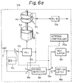
- Figs. 6a and 6b show a second preferred embodiment of the present invention.
- the second embodiment will be described in detail with reference particularly to Fig. 6a, which shows disk drive 41a, which is one of the three disk drives 41a, 41b and 41c that are included in this second preferred embodiment.
- Disk drives 1b and 1c may have a construction like disk drive 41a.
- This embodiment is similar to the first preferred embodiment shown in Figs. 2a and 2b, except the second preferred embodiment uses only one period detector 9a (see Fig. 6a). More particularly, the period detector 14a (Fig. 2a) is eliminated and switches 18a and 19a (Fig. 6a) are added.
- An internal controller 20a is provided to control switches 18a and 19a.
- the period detector 9a may be implemented using a circuit like that shown in Fig. 3. When the contact of the switch 18a is positioned to touch the side "b", the period detector 9a monitors the output of the index sensor 7a, whereas when the contact is connected to side "a", the period detector 9a monitors the external synchronizing signal 2.
- the set/reset operation for ready latch 13a and reference-OK latch 16a is performed in a fashion like that described for the first preferred embodiment.
- the outputs of the respective ready latches 13a, 13b and 13c (Fig. 6b) included in the disk array system are supplied to an AND circuit 12 of the controller 3.
- the outputs of the respective reference-OK latches 16a, 16b and 16c are also supplied to an AND circuit (not shown) of the controller 3.
- the outputs of those AND circuits are used for determining whether the disk array system is operating properly.
- switch 17a (Fig. 6a) is thrown to side “b” to supply PLL 8a with the external synchronizing signal.
- Switch 18a is thrown to the side “a” to supply the external synchronizing signal 2 to period detector 9a, and switch 19a is thrown to side "a” to provide the output of the period detector to the reference-OK latch 16a.
- the switches 17a and 18a are shifted so that the contact of switch 17a is connected to side "a", the contact of switch 18a is connected to side "b", and the contact of switch 19a is connected to side "b".
- the switching of switch 17a to contact "a” causes the internal synchronizing signal from generator 15a to be supplied to PLL 8a to control the rotation of spindle motor 6a.
- the switching of the contact of switch 18a to side “b” causes the output of index sensor 7a to be monitored by the period detector 9a, which is monitoring the external synchronizing signal 2.
- the switching of the contact of switch 19a to side “b” causes the output of the period detector to be passed to ready latch 13a.
- the rotation of magnetic disks 4a, 4b and 4c in the respective disk drives of the disk drive array system are usually synchronized by a common external synchronizing signal as if all of the disk drives were a single disk drive. Even if the synchronized rotation of the disks is not possible due to the irregularity of the external signal, the loss of data can be avoided by replacing the external signal with the internal reference signal.
- Fig. 7 shows a third preferred embodiment of the present invention.
- Disk drive 51a differs from disk drives 51b and 51c in this third embodiment.
- disk drives 51b and 51c include switches 17b and 17c, respectively, like counterpart switches provided in the first embodiment of Fig. 2.
- Disk drive 51a does not include a switch 17a, as is provided in Fig. 2. Rather, the output of the internal synchronizing signal generator 15a is used as the reference signal within disk drive 51a.
- the external synchronizing signal 2 is not used.
- Magnetic disk drive 51a is used as a master disk drive for the two slave drives 51b and 51c. In other words, the internal synchronizing signal generator 15a provides the reference signal for the other disk drives 51b and 51c.
- the period detectors 9a, 9b and 9c and 14a, 14b and 14c may be constructed by discrete electronic devices or a microprocessor, to measure the time periods for monitoring signals.
- the switches 17a, 17b and 17c and 18a, 18b and 18c may be mechanical switches or formed from electronic circuits.
Landscapes
- Rotational Drive Of Disk (AREA)
- Signal Processing For Digital Recording And Reproducing (AREA)
Applications Claiming Priority (2)
| Application Number | Priority Date | Filing Date | Title |
|---|---|---|---|
| JP171216/91 | 1991-07-11 | ||
| JP3171216A JPH0520771A (ja) | 1991-07-11 | 1991-07-11 | アレイ形デイスク装置 |
Publications (2)
| Publication Number | Publication Date |
|---|---|
| EP0522592A1 true EP0522592A1 (fr) | 1993-01-13 |
| EP0522592B1 EP0522592B1 (fr) | 1997-11-12 |
Family
ID=15919194
Family Applications (1)
| Application Number | Title | Priority Date | Filing Date |
|---|---|---|---|
| EP92111821A Expired - Lifetime EP0522592B1 (fr) | 1991-07-11 | 1992-07-10 | Système de réseau de disques comprenant une synchronisation interne et un monitoring de synchronisation externe |
Country Status (5)
| Country | Link |
|---|---|
| US (1) | US5497276A (fr) |
| EP (1) | EP0522592B1 (fr) |
| JP (1) | JPH0520771A (fr) |
| CA (1) | CA2073544C (fr) |
| DE (1) | DE69223093T2 (fr) |
Cited By (1)
| Publication number | Priority date | Publication date | Assignee | Title |
|---|---|---|---|---|
| EP0643389A1 (fr) * | 1993-09-10 | 1995-03-15 | International Business Machines Corporation | Appareil et méthode de synchronisation d'axe de lecteur de disque |
Families Citing this family (3)
| Publication number | Priority date | Publication date | Assignee | Title |
|---|---|---|---|---|
| JP3971462B2 (ja) * | 1994-11-25 | 2007-09-05 | ソニー株式会社 | ディスク再生装置 |
| TW337580B (en) * | 1996-07-24 | 1998-08-01 | Hitachi Ltd | Disc reproducing method and disc reproducing apparatus |
| US5896280A (en) | 1997-11-25 | 1999-04-20 | Exide Electronics Corporation | Frequency converter and improved UPS employing the same |
Citations (4)
| Publication number | Priority date | Publication date | Assignee | Title |
|---|---|---|---|---|
| EP0276744A2 (fr) * | 1987-01-29 | 1988-08-03 | Fujitsu Limited | Système de commande de rotation synchrone de disque d'enregistrement magnétique |
| EP0332099A2 (fr) * | 1988-03-07 | 1989-09-13 | Nec Corporation | Circuit de commande pour arbre moteur |
| US4890045A (en) * | 1987-12-28 | 1989-12-26 | Nec Corporation | Spindle motor control system for magnetic disk apparatus |
| EP0404120A2 (fr) * | 1989-06-23 | 1990-12-27 | Fujitsu Limited | Système de commutation de signaux de synchronisation pour la synchronisation des dispositifs de stockages externes |
Family Cites Families (7)
| Publication number | Priority date | Publication date | Assignee | Title |
|---|---|---|---|---|
| JPS60134466A (ja) * | 1983-12-23 | 1985-07-17 | Hitachi Ltd | 半導体装置およびその製造方法 |
| JPS60195773A (ja) * | 1984-03-15 | 1985-10-04 | Konishiroku Photo Ind Co Ltd | 磁気記録再生装置 |
| JPH0743894B2 (ja) * | 1986-06-30 | 1995-05-15 | 株式会社東芝 | 磁気記録再生装置 |
| US5289448A (en) * | 1987-08-31 | 1994-02-22 | Asahi Kogaku Kogyo Kabushiki Kaisha | Rotation control apparatus for use with recording medium |
| JPH0369061A (ja) * | 1989-08-07 | 1991-03-25 | Pioneer Electron Corp | 光ディスク記録再生装置のスピンドル制御装置 |
| US5237466A (en) * | 1989-11-02 | 1993-08-17 | International Business Machines Corporation | Method and apparatus for programmably controlling spindle synchronization and phase among disk drives in a storage subsystem |
| JPH0453060A (ja) * | 1990-06-20 | 1992-02-20 | Yokogawa Electric Corp | ミラードディスク装置 |
-
1991
- 1991-07-11 JP JP3171216A patent/JPH0520771A/ja active Pending
-
1992
- 1992-07-08 US US07/910,641 patent/US5497276A/en not_active Expired - Fee Related
- 1992-07-09 CA CA002073544A patent/CA2073544C/fr not_active Expired - Fee Related
- 1992-07-10 DE DE69223093T patent/DE69223093T2/de not_active Expired - Fee Related
- 1992-07-10 EP EP92111821A patent/EP0522592B1/fr not_active Expired - Lifetime
Patent Citations (4)
| Publication number | Priority date | Publication date | Assignee | Title |
|---|---|---|---|---|
| EP0276744A2 (fr) * | 1987-01-29 | 1988-08-03 | Fujitsu Limited | Système de commande de rotation synchrone de disque d'enregistrement magnétique |
| US4890045A (en) * | 1987-12-28 | 1989-12-26 | Nec Corporation | Spindle motor control system for magnetic disk apparatus |
| EP0332099A2 (fr) * | 1988-03-07 | 1989-09-13 | Nec Corporation | Circuit de commande pour arbre moteur |
| EP0404120A2 (fr) * | 1989-06-23 | 1990-12-27 | Fujitsu Limited | Système de commutation de signaux de synchronisation pour la synchronisation des dispositifs de stockages externes |
Non-Patent Citations (3)
| Title |
|---|
| PATENT ABSTRACTS OF JAPAN vol. 10, no. 52 (P-432)28 February 1986 & JP-A-60 195773 ( KONISHIROKU SHASHIN KOGYO K.K. ) 4 October 1985 * |
| PATENT ABSTRACTS OF JAPAN vol. 16, no. 243 (P-1346)4 June 1992 & JP-A-04 053060 ( YOKOGAWA ELECTRIC CORP ) 20 February 1992 * |
| PATENT ABSTRACTS OF JAPAN vol. 9, no. 320 (P-413)14 December 1985 & JP-A-60 145566 ( RICOH K.K. ) 1 August 1985 * |
Cited By (3)
| Publication number | Priority date | Publication date | Assignee | Title |
|---|---|---|---|---|
| EP0643389A1 (fr) * | 1993-09-10 | 1995-03-15 | International Business Machines Corporation | Appareil et méthode de synchronisation d'axe de lecteur de disque |
| US5491593A (en) * | 1993-09-10 | 1996-02-13 | International Business Machines Corporation | Disk drive spindle synchronization apparatus and method |
| US6134068A (en) * | 1993-09-10 | 2000-10-17 | International Business Machines Corporation | Disk drive spindle synchronization apparatus and method |
Also Published As
| Publication number | Publication date |
|---|---|
| DE69223093T2 (de) | 1998-04-30 |
| CA2073544C (fr) | 1996-01-16 |
| DE69223093D1 (de) | 1997-12-18 |
| US5497276A (en) | 1996-03-05 |
| EP0522592B1 (fr) | 1997-11-12 |
| JPH0520771A (ja) | 1993-01-29 |
| CA2073544A1 (fr) | 1993-01-12 |
Similar Documents
| Publication | Publication Date | Title |
|---|---|---|
| JP2554719B2 (ja) | 記録データ読取り方式 | |
| EP0075948B1 (fr) | Système de contrôle de vitesse de lecture | |
| US5327300A (en) | Digital information reproducing apparatus including a circuit for detecting frequency deviation of a synchronism clock | |
| KR100232423B1 (ko) | 광디스크용 재생속도 제어장치 | |
| JPH04134762A (ja) | 光ディスク再生装置 | |
| GB2112968A (en) | Time base control unit in an apparatus for reproducing recorded information from a recording disc | |
| JPS623498B2 (fr) | ||
| US4651277A (en) | Control system for a magnetic disk drive unit | |
| US5216654A (en) | Synchronizing signal switching system for synchronizing external storage devices | |
| KR100329400B1 (ko) | 엠베디드-서보,구역-데이타기록디스크드라이브장치에 있어서 스플릿포맷의신뢰할수 있는 시간영역구분회로및그방법 | |
| EP0522592A1 (fr) | Système de réseau de disques comprenant un monitoring de synchronisation interne et de synchronisation externe | |
| US4143407A (en) | Magnetic data storage and retrieval system | |
| KR950003994B1 (ko) | 디스크 동기 제어 장치 및 동기 제어 방법 | |
| US5841604A (en) | Masterless spindle synchronization in a multiple disk drive storage system | |
| US5267097A (en) | Information transfer control system having rotary storage unit which uses a pseudo address mark | |
| JP3028819B2 (ja) | Pll回路のロツク,アンロツク検出回路 | |
| US5124808A (en) | Spindle control device in optical disk recording/reproducing apparatus | |
| US5355260A (en) | Servo system for positioning a read/write head within a storage device with means for detecting malfunctions in the servo data | |
| JPH01307317A (ja) | Pll回路 | |
| JP3251007B2 (ja) | デイスクドライブ装置 | |
| JPH04319575A (ja) | Pll回路の制御方法およびpll回路 | |
| KR100489414B1 (ko) | 서보클럭신호의 안정도 판별장치 | |
| JPH02179287A (ja) | 回転サーボ制御方式 | |
| JPS61165862A (ja) | 記録情報認識装置 | |
| JPH05120812A (ja) | フロツピーデイスク制御装置 |
Legal Events
| Date | Code | Title | Description |
|---|---|---|---|
| PUAI | Public reference made under article 153(3) epc to a published international application that has entered the european phase |
Free format text: ORIGINAL CODE: 0009012 |
|
| 17P | Request for examination filed |
Effective date: 19920710 |
|
| AK | Designated contracting states |
Kind code of ref document: A1 Designated state(s): DE FR GB |
|
| 17Q | First examination report despatched |
Effective date: 19951012 |
|
| GRAG | Despatch of communication of intention to grant |
Free format text: ORIGINAL CODE: EPIDOS AGRA |
|
| GRAH | Despatch of communication of intention to grant a patent |
Free format text: ORIGINAL CODE: EPIDOS IGRA |
|
| GRAH | Despatch of communication of intention to grant a patent |
Free format text: ORIGINAL CODE: EPIDOS IGRA |
|
| GRAA | (expected) grant |
Free format text: ORIGINAL CODE: 0009210 |
|
| AK | Designated contracting states |
Kind code of ref document: B1 Designated state(s): DE FR GB |
|
| REF | Corresponds to: |
Ref document number: 69223093 Country of ref document: DE Date of ref document: 19971218 |
|
| ET | Fr: translation filed | ||
| PLBE | No opposition filed within time limit |
Free format text: ORIGINAL CODE: 0009261 |
|
| STAA | Information on the status of an ep patent application or granted ep patent |
Free format text: STATUS: NO OPPOSITION FILED WITHIN TIME LIMIT |
|
| 26N | No opposition filed | ||
| REG | Reference to a national code |
Ref country code: GB Ref legal event code: 746 Effective date: 20000126 |
|
| REG | Reference to a national code |
Ref country code: FR Ref legal event code: D6 |
|
| REG | Reference to a national code |
Ref country code: GB Ref legal event code: IF02 |
|
| PGFP | Annual fee paid to national office [announced via postgrant information from national office to epo] |
Ref country code: GB Payment date: 20060705 Year of fee payment: 15 |
|
| PGFP | Annual fee paid to national office [announced via postgrant information from national office to epo] |
Ref country code: DE Payment date: 20060706 Year of fee payment: 15 |
|
| PGFP | Annual fee paid to national office [announced via postgrant information from national office to epo] |
Ref country code: FR Payment date: 20060719 Year of fee payment: 15 |
|
| GBPC | Gb: european patent ceased through non-payment of renewal fee |
Effective date: 20070710 |
|
| PG25 | Lapsed in a contracting state [announced via postgrant information from national office to epo] |
Ref country code: DE Free format text: LAPSE BECAUSE OF NON-PAYMENT OF DUE FEES Effective date: 20080201 |
|
| PG25 | Lapsed in a contracting state [announced via postgrant information from national office to epo] |
Ref country code: GB Free format text: LAPSE BECAUSE OF NON-PAYMENT OF DUE FEES Effective date: 20070710 |
|
| REG | Reference to a national code |
Ref country code: FR Ref legal event code: ST Effective date: 20080331 |
|
| PG25 | Lapsed in a contracting state [announced via postgrant information from national office to epo] |
Ref country code: FR Free format text: LAPSE BECAUSE OF NON-PAYMENT OF DUE FEES Effective date: 20070731 |