EP0522608A1 - Balance électronique avec un dispositif pour contrôler l'arrêt - Google Patents
Balance électronique avec un dispositif pour contrôler l'arrêt Download PDFInfo
- Publication number
- EP0522608A1 EP0522608A1 EP92201342A EP92201342A EP0522608A1 EP 0522608 A1 EP0522608 A1 EP 0522608A1 EP 92201342 A EP92201342 A EP 92201342A EP 92201342 A EP92201342 A EP 92201342A EP 0522608 A1 EP0522608 A1 EP 0522608A1
- Authority
- EP
- European Patent Office
- Prior art keywords
- standstill
- tolerance range
- balance
- quasi
- stable
- Prior art date
- Legal status (The legal status is an assumption and is not a legal conclusion. Google has not performed a legal analysis and makes no representation as to the accuracy of the status listed.)
- Withdrawn
Links
- 238000005303 weighing Methods 0.000 claims abstract description 32
- 238000000034 method Methods 0.000 claims description 10
- 230000003287 optical effect Effects 0.000 claims description 6
- 230000008033 biological extinction Effects 0.000 claims description 2
- 230000001052 transient effect Effects 0.000 claims 1
- 238000010586 diagram Methods 0.000 description 3
- 230000000694 effects Effects 0.000 description 2
- 230000006978 adaptation Effects 0.000 description 1
- 230000001174 ascending effect Effects 0.000 description 1
- 238000001514 detection method Methods 0.000 description 1
- 230000002349 favourable effect Effects 0.000 description 1
- 238000005259 measurement Methods 0.000 description 1
- 230000010355 oscillation Effects 0.000 description 1
- 238000002360 preparation method Methods 0.000 description 1
- 230000000717 retained effect Effects 0.000 description 1
- 230000011664 signaling Effects 0.000 description 1
- 230000006641 stabilisation Effects 0.000 description 1
- 238000011105 stabilization Methods 0.000 description 1
- 230000007704 transition Effects 0.000 description 1
Images

Classifications
-
- G—PHYSICS
- G01—MEASURING; TESTING
- G01G—WEIGHING
- G01G23/00—Auxiliary devices for weighing apparatus
- G01G23/18—Indicating devices, e.g. for remote indication; Recording devices; Scales, e.g. graduated
- G01G23/36—Indicating the weight by electrical means, e.g. using photoelectric cells
- G01G23/37—Indicating the weight by electrical means, e.g. using photoelectric cells involving digital counting
- G01G23/3707—Indicating the weight by electrical means, e.g. using photoelectric cells involving digital counting using a microprocessor
- G01G23/3721—Indicating the weight by electrical means, e.g. using photoelectric cells involving digital counting using a microprocessor with particular representation of the result, e.g. graphic
-
- G—PHYSICS
- G01—MEASURING; TESTING
- G01G—WEIGHING
- G01G23/00—Auxiliary devices for weighing apparatus
- G01G23/18—Indicating devices, e.g. for remote indication; Recording devices; Scales, e.g. graduated
- G01G23/38—Recording and/or coding devices specially adapted for weighing apparatus
- G01G23/46—Devices preventing recording until the weighing mechanism has come to rest
-
- G—PHYSICS
- G01—MEASURING; TESTING
- G01G—WEIGHING
- G01G23/00—Auxiliary devices for weighing apparatus
- G01G23/18—Indicating devices, e.g. for remote indication; Recording devices; Scales, e.g. graduated
- G01G23/36—Indicating the weight by electrical means, e.g. using photoelectric cells
- G01G23/37—Indicating the weight by electrical means, e.g. using photoelectric cells involving digital counting
- G01G23/3707—Indicating the weight by electrical means, e.g. using photoelectric cells involving digital counting using a microprocessor
Definitions
- the invention relates to an electronic balance with a device for checking the standstill, which device determines the point in time at which the changes in the measured value when the scale starts to oscillate no longer exceed a specific one of a plurality of predetermined tolerance ranges, and also with display means which indicate the quasi-stable standstill of the Signal the time marking the balance.
- the operating modes and the operating parameters of the scale can be set in a setting mode, which determine the course of the weighing process in consideration of the boundary conditions in the weighing mode of the scale.
- the tolerance range which the fluctuations in the weighing result to be recorded should not exceed, can be determined in the setting mode based on the accuracy requirements.
- the state is finally reached in which the measured value only changes within the specific tolerance range and does not exceed it even in the course of a specific waiting time. Only at the point in time at the end of this waiting period is there a guarantee that the measured value will be recorded with the required accuracy and can therefore be read off or released for any further processing.
- This point in time which marks the quasi-stable standstill of the balance, is determined in a standstill control device and the balance user e.g. signaled by an indicator lamp going out.
- the lighting of this indicator lamp during a weighing process indicates that the quasi-stable standstill has not yet been reached.
- a disadvantage of the weighing aid described, which is very useful per se, in certain applications is the fact that the tolerance range preselected in the setting mode of the balance is no longer displayed in the weighing mode because the relevant one Display means are also assigned to other options and as a result the tolerance range display disappears when you exit the setting mode of the balance.
- display means specifically for displaying the tolerance range the display of which remains when switching from the setting mode to the weighing mode of the balance.
- such a solution would take up additional space in the display field of the balance and would run counter to the general endeavor to achieve the simplest possible overall presentation of all the data required for recording a weighing result.
- the invention aims to improve the balance of the type mentioned in that the disadvantages described be avoided, and also to create the possibility that the balance user is informed during the weighing of the tolerance range in which the weighing result is, without having to leave the weighing mode of the balance to obtain this information.
- this object is achieved in that display means are provided which indicate the respectively applicable tolerance range during the weighing process, and that the device for checking the standstill contains control means which, by changing this display, signal the time of the respective quasi-stable standstill of the balance.
- the combination of the tolerance range display with the standstill display in accordance with the invention avoids a larger space requirement for the display means and also simplifies the handling of the balance and facilitates the recording of the weighing result.
- a plurality of optical indicators can be provided as a display means, for example, which can be activated individually or in groups by the control means, the position of an indicator in the group representing the respective tolerance range displays and the lighting or extinguishing of an indicator signals the quasi-stable standstill of the balance within the tolerance range assigned to this indicator.
- the indicators can, for example, be ring-shaped and arranged in concentric circles.
- Another embodiment of the display means can be to provide an indicator with luminous digits that can be optionally activated by the control means to indicate the respective tolerance range, the lighting up or the extinction of a number indicating the quasi-stable standstill of the balance in the tolerance range indicated by this number in the activated state.
- a further development of the invention consists in the fact that the device for the standstill control contains control means which automatically switch over the predetermined tolerance ranges as a function of the settling amplitude of the measured value, in such a way that when the quasi-stable standstill of the balance is reached within one tolerance range in each case to the next smaller tolerance range is switched.
- the change in the different tolerance ranges is continuously displayed in this way.
- This operating mode in which the tolerance range is not preselected, enables the user of the balance to record the tolerance ranges traversed by the measured value when the balance settles and for each individual weighing read the measurement result when the quasi-stable standstill of the balance is signaled by the range switchover within the tolerance range relevant for the weighing in question.
- control means mentioned can be designed such that when the quasi-stable standstill of the balance is left within a tolerance range, the system switches over to the next larger tolerance range.
- control means also react to external influences which disturb the quasi-stable balance of the balance.
- the tolerance range in which the measured value amplitude is currently moving is always displayed in the course of a weighing process.
- a common display device for displaying the tolerance range and for signaling the quasi-stable standstill of the balance leads to two possible solutions with regard to the standstill display in the case of optical indicators which are either illuminated or dark, in that the indicators either light up in the dynamic range of the weighing process and become dark when changing to the stable range or are dark in the dynamic range and light up when changing to the stable range.
- the tolerance range in weighing mode is therefore only displayed either during settling or during quasi-stable standstill of the balance. Which of these two solutions is preferred is given, ie which display mode is used depends on other factors, for example, whether you are working with a single-level standstill display or with a multi-level standstill display to visualize the stabilization process.
- the tolerance range is preset and the standstill display is a one-time process for each weighing. It is not particularly critical here whether the display goes out or lights up when the scale changes to the quasi-stable transition, ie the display mode that has been used up to now is retained.
- the tolerance range is not preset so that the indicators assigned to the individual tolerance ranges come into effect one after the other as the balance settles and thus continuously show in which of the increasingly narrow tolerance ranges the quasi-stable standstill of the balance is reached has been. In this case, the display mode appears more favorable, in which the quasi-stable standstill is indicated by the indicator lighting up.
- the 1 comprises a weight sensor GS, from which the raw value x of the measured weight is taken using an A / D converter.
- the weight value y and the first and second derivatives y 'and y''of the same are formed in a digital filter F, for example 2nd or 4th order.
- the weight value y reaches the result display RA in the display field AF via a device AA for display preparation.
- the stability detector ASD determines the point in time at which the changes in the measured value y no longer exceeds a certain one of several predetermined tolerance ranges when the balance swings.
- the stability detector ASD signals this point in time by dark or light control of an optical indicator in a standstill display SA arranged in the display field.
- a standstill display SA arranged in the display field.
- further display means AM for other weighing parameters. However, this will not be discussed in more detail here.
- the display means of the standstill display SA consist of several optical indicators 1, 2, 3 and 4, which are ring-shaped and arranged in concentric circles.
- a tolerance range is assigned to each of these ring-shaped indicators, whereby - similar to a shooting target - the largest ring 1 marks the largest tolerance range or the largest permitted scatter of the measured value and the smallest ring 4 the smallest tolerance range or the smallest permitted scatter of the measured value.
- These indicators are surrounded by a square frame formed from two parts 5 and 6, which lights up continuously during operation of the scale and is intended to make it easier to distinguish between individually activated indicators by comparing them with the frame size.
- an indicator 7 with selectively controllable indicators can also be used as the display means for the standstill indicator SA Luminous digits 8 can be provided.
- the means for controlling this indicator 7 remain essentially the same as in the arrangement according to FIG. 2.
- the desired tolerance range is preset in the setting mode of the balance, the indicator of indicators 1 to 4 assigned to this tolerance range being light-controlled. Depending on the selected display mode, this display remains when the scale is switched to weighing mode or goes out. Accordingly, reaching the quasi-stable state of the scale within the tolerance range assigned to this indicator is signaled by dark or light control of this indicator.
- the tolerance range used is therefore also displayed in the weighing mode of the balance, either during the settling of the balance or during the standstill phase.
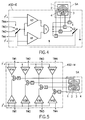
- FIG. 4 The basic structure of an automatic stability detector ASD-E for the single-stage standstill display is shown in FIG. 4.
- a switch U1 is used to preselect the tolerance value of the tolerance values TW1 to TW4 which is to be decisive for the intended weighing. It is assumed that TW1 defines the largest and TW4 the smallest tolerance range.
- the set tolerance value in the present example TW1, reaches two comparison stages V1 and V2, for example in the form of microprocessors.
- the derivatives y 'and y''of the settling weight value y are fed individually to the comparison stages V1 and V2 and compared with the tolerance value TW1.
- the relevant comparison stage V1 or V2 delivers an output signal.
- the outputs of the comparison stages V1 and V2 are connected to a summation element S, at whose output a signal occurs when an output signal is present at both comparison stages V1 and V2.
- the output signal of the sum element S is used to control the driver stages T, which are individually assigned to the indicators 1 to 4 of the standstill display SA.
- the driver stage T assigned to a specific indicator is switched on by a changeover switch U2, which is coupled to the changeover switch U1 via the connection 9.
- the indicator 1 in the event of a quasi-stable standstill of the balance in the tolerance range defined by the tolerance value TW1, the indicator 1 is dark or light-controlled. As can be seen, the indicator 1 is the one with the largest diameter, corresponding to the largest tolerance value set.
- the electronic means for signal processing in the manner described are known per se and are not described in detail here.
- the multi-level standstill display does not require a specific tolerance range, and The applicable tolerance range is only displayed during a weighing process, i.e. in the weighing mode of the balance. As the balance swings, the indicators assigned to the individual tolerance ranges come into effect one after the other and indicate in which of the increasingly narrow tolerance ranges the quasi-stable standstill of the balance has been reached.
- the automatic stability detector ASD-M according to FIG. 5 for a multi-stage standstill display contains, in comparison to FIG. 4, an arrangement with two comparison stages V1A, V1B for each tolerance value TW1 to TW4; V2A, V2B; V3A, V3B or V4A, V4B, a sum element S and a driver stage T for the respective indicator 1, 2, 3 or 4 of the standstill display SA.
- the signal to be monitored y ' is fed to the comparison stages V1A, V2A, V3A and V4A and the signal to be monitored y' 'is fed to the comparison stages V1B, V2B, V3B and V4B.
- this stability detector works in a similar manner to that according to FIG. 4, with the difference that the indicators 1 to 4 are activated in succession when the measured value amplitude has decayed when the quasi-stable standstill of the balance is reached in the relevant tolerance range.
- 6 and 7 show two possible variants for the continuous display of the tolerance ranges and the associated tolerance ranges that have passed when the measured value amplitude has decayed Standstill indicators.
- the standstill indicator SA is controlled such that when the quasi-stable standstill is reached within the largest predetermined tolerance range, the indicator 1 with the largest ring diameter lights up and when the quasi-stable standstill is reached within the next smaller tolerance range, the previously active indicator goes out and the Indicator 2, 3 or 4 lights up with the next smaller ring diameter.
- the indicator 4 with the smallest ring diameter appears here as a point.
- the standstill display SA according to FIG. 7 can also be controlled so that when the quasi-stable standstill is reached within the largest specified tolerance range, all indicators 1 to 4 first light up and then the outermost ring disappears as soon as the quasi-stable standstill in the next smaller tolerance range is reached.
- the standstill display also shows the tolerance range for which the quasi-stable standstill of the balance is signaled.
- control means for the device for checking the standstill can be developed in such a way that if the quasi-stable standstill of the scale is not reached within of a tolerance range is switched over to the next larger tolerance range.
- the other control means for switching the displayed tolerance ranges in the ascending or descending sense essentially consist of switching stages which detect the presence of an output signal on the sum elements S of the automatic stability detector ASD-M and a change in the signal state in a switching function for switching the relevant one on or off Implement driver stage T.
Landscapes
- Physics & Mathematics (AREA)
- General Physics & Mathematics (AREA)
- Engineering & Computer Science (AREA)
- Computer Hardware Design (AREA)
- Microelectronics & Electronic Packaging (AREA)
- Indication And Recording Devices For Special Purposes And Tariff Metering Devices (AREA)
- Indicating Measured Values (AREA)
Applications Claiming Priority (2)
| Application Number | Priority Date | Filing Date | Title |
|---|---|---|---|
| CH20341/91 | 1991-07-09 | ||
| CH2034/91A CH682518A5 (de) | 1991-07-09 | 1991-07-09 | Elektronische Waage mit einer Einrichtung zur Stillstandskontrolle. |
Publications (1)
| Publication Number | Publication Date |
|---|---|
| EP0522608A1 true EP0522608A1 (fr) | 1993-01-13 |
Family
ID=4224381
Family Applications (1)
| Application Number | Title | Priority Date | Filing Date |
|---|---|---|---|
| EP92201342A Withdrawn EP0522608A1 (fr) | 1991-07-09 | 1992-05-12 | Balance électronique avec un dispositif pour contrôler l'arrêt |
Country Status (5)
| Country | Link |
|---|---|
| US (1) | US5220970A (fr) |
| EP (1) | EP0522608A1 (fr) |
| JP (1) | JPH0530739U (fr) |
| CH (1) | CH682518A5 (fr) |
| DE (1) | DE9207513U1 (fr) |
Cited By (1)
| Publication number | Priority date | Publication date | Assignee | Title |
|---|---|---|---|---|
| EP2853180A3 (fr) * | 2013-09-25 | 2015-07-15 | Teraoka Seiko Co., Ltd. | Appareil d'alignement d'articles et dispositif de mesure |
Families Citing this family (15)
| Publication number | Priority date | Publication date | Assignee | Title |
|---|---|---|---|---|
| US5936206A (en) * | 1993-12-31 | 1999-08-10 | Ishida Co., Ltd. | Weighing machines with means for correcting effects of floor vibrations on weight signals therefrom |
| FR2814541B1 (fr) * | 2000-09-27 | 2002-12-13 | Aerospatiale Matra Airbus | Dispositif de pesee d'un objet par soulevement |
| JP2002357476A (ja) * | 2001-03-26 | 2002-12-13 | Takata Corp | シート重量計測装置 |
| US7044370B2 (en) | 2001-07-02 | 2006-05-16 | Ecr Software Corporation | Checkout system with a flexible security verification system |
| RU2286554C2 (ru) * | 2004-06-16 | 2006-10-27 | Закрытое акционерное общество "ТЕНЗО-М" | Устройство для измерения веса |
| FR2872612B1 (fr) * | 2004-06-30 | 2006-11-10 | Neopost Ind Sa | Dispositif d'alimentation a module de pesee differentielle integre |
| JP4579091B2 (ja) * | 2004-11-09 | 2010-11-10 | 株式会社タニタ | デジタル測定装置 |
| CN101080616B (zh) * | 2005-02-04 | 2011-04-06 | 株式会社岛津制作所 | 带有风挡的电子秤 |
| EP1798470B1 (fr) | 2005-12-13 | 2008-03-05 | Schwank GmbH | Dispositif de chauffage et son procédé de fonctionnement |
| JP4801988B2 (ja) * | 2005-12-22 | 2011-10-26 | カルソニックカンセイ株式会社 | 車両用乗員検知装置 |
| JP2008057988A (ja) * | 2006-08-29 | 2008-03-13 | Tanita Corp | デジタル重量計 |
| CH704466A1 (de) * | 2011-02-11 | 2012-08-15 | Digi Sens Ag | Verfahren und Vorrichtung zum Messen des Gewichts einer auf eine Ladefläche zu hievenden Last. |
| JP6264835B2 (ja) * | 2013-09-25 | 2018-01-24 | 株式会社寺岡精工 | 計量装置及び計量システム |
| JP6616703B2 (ja) * | 2016-02-03 | 2019-12-04 | 株式会社イシダ | 計量装置 |
| JP7324532B2 (ja) * | 2021-06-29 | 2023-08-10 | 株式会社寺岡精工 | 計量装置及びプログラム |
Citations (4)
| Publication number | Priority date | Publication date | Assignee | Title |
|---|---|---|---|---|
| DE2250793B1 (de) * | 1972-10-17 | 1973-08-23 | Sartonus Werke GmbH (und vormals Gottinger Prazisionswaagenfabnk GmbH), 3400 Gottingen | Verfahren zur digitalen stillstandskontrolle |
| CH544294A (de) * | 1972-06-27 | 1973-11-15 | Mettler Instrumente Ag | Elektrische Waage |
| DE2601150A1 (de) * | 1976-01-14 | 1977-07-21 | Sartorius Werke Gmbh | Verfahren und schaltungsanordnung zur bildung von signalen fuer eine stillstandskontrolle eines elektrischen messwertgebers, insbesondere einer elektromagnetischen praezisions- und feinwaage |
| EP0132054A2 (fr) * | 1983-06-30 | 1985-01-23 | Shimadzu Corporation | Balance électronique |
Family Cites Families (6)
| Publication number | Priority date | Publication date | Assignee | Title |
|---|---|---|---|---|
| CH618508A5 (fr) * | 1977-08-26 | 1980-07-31 | Mettler Instrumente Ag | |
| JPS593326A (ja) * | 1982-06-30 | 1984-01-10 | Shimadzu Corp | 電子はかりの表示装置 |
| JPS5972027A (ja) * | 1982-10-18 | 1984-04-23 | Shimadzu Corp | 電子はかりの表示装置 |
| JPS59159027A (ja) * | 1983-02-28 | 1984-09-08 | Shimadzu Corp | 電子天びん |
| US4782904A (en) * | 1986-11-07 | 1988-11-08 | Ohaus Scale Corporation | Electronic balance |
| US4825966A (en) * | 1988-01-12 | 1989-05-02 | Cardinal Scale Manufacturing Company | Weigh scale with digital and discrete fractional weight indicators |
-
1991
- 1991-07-09 CH CH2034/91A patent/CH682518A5/de not_active IP Right Cessation
-
1992
- 1992-05-05 US US07/878,473 patent/US5220970A/en not_active Expired - Fee Related
- 1992-05-12 EP EP92201342A patent/EP0522608A1/fr not_active Withdrawn
- 1992-06-03 DE DE9207513U patent/DE9207513U1/de not_active Expired - Lifetime
- 1992-07-02 JP JP046222U patent/JPH0530739U/ja active Pending
Patent Citations (4)
| Publication number | Priority date | Publication date | Assignee | Title |
|---|---|---|---|---|
| CH544294A (de) * | 1972-06-27 | 1973-11-15 | Mettler Instrumente Ag | Elektrische Waage |
| DE2250793B1 (de) * | 1972-10-17 | 1973-08-23 | Sartonus Werke GmbH (und vormals Gottinger Prazisionswaagenfabnk GmbH), 3400 Gottingen | Verfahren zur digitalen stillstandskontrolle |
| DE2601150A1 (de) * | 1976-01-14 | 1977-07-21 | Sartorius Werke Gmbh | Verfahren und schaltungsanordnung zur bildung von signalen fuer eine stillstandskontrolle eines elektrischen messwertgebers, insbesondere einer elektromagnetischen praezisions- und feinwaage |
| EP0132054A2 (fr) * | 1983-06-30 | 1985-01-23 | Shimadzu Corporation | Balance électronique |
Cited By (2)
| Publication number | Priority date | Publication date | Assignee | Title |
|---|---|---|---|---|
| EP2853180A3 (fr) * | 2013-09-25 | 2015-07-15 | Teraoka Seiko Co., Ltd. | Appareil d'alignement d'articles et dispositif de mesure |
| US9354107B2 (en) | 2013-09-25 | 2016-05-31 | Teraoka Seiko Co., Ltd. | Item registration apparatus and measuring device |
Also Published As
| Publication number | Publication date |
|---|---|
| JPH0530739U (ja) | 1993-04-23 |
| CH682518A5 (de) | 1993-09-30 |
| US5220970A (en) | 1993-06-22 |
| DE9207513U1 (de) | 1992-11-12 |
Similar Documents
| Publication | Publication Date | Title |
|---|---|---|
| CH682518A5 (de) | Elektronische Waage mit einer Einrichtung zur Stillstandskontrolle. | |
| DE2829085C2 (fr) | ||
| DE3620723C2 (de) | Verfahren und digitales Meßgerät zum Anzeigen eines sich zeitlich ändernden Meßwertes | |
| EP0078463B1 (fr) | Contrôle continu de la charge des couches électrochromiques | |
| DE2817562C2 (de) | Elektrische Waage | |
| DE3714072A1 (de) | Messgeraet | |
| DE3407942C2 (fr) | ||
| DD146342A5 (de) | Verfahren und vorrichtung zur messung der mehlhelligkeit | |
| DE2718769C2 (de) | Waage mit Digitalanzeige | |
| EP0066682B1 (fr) | Dispositif de positionnement | |
| DE3238487A1 (de) | Verfahren zur darstellungphysiklischer messgroessen auf einer analogskala sowie elektrische schaltungsanordnung zur durchfuehrung des verfahrens | |
| DE2727800B2 (de) | Schaltungsanordnung zum Betrieb und zur Funktionsfehlerüberwachung für LED-Anzeigen | |
| DE3332750C2 (de) | Farbmarkentaster | |
| DE2939801C2 (de) | Gerät für die Messung analoger, in elektrische Signale umgesetzter Größen | |
| DE2756058A1 (de) | Programmierbare spannungsfuehlschaltung | |
| DE3035568C2 (de) | Anzeigesystem für fotografische Kameras | |
| DE2615459C2 (de) | Verfahren zum Aussteuern eines Digitalmeßgerätes | |
| AT367328B (de) | Vorrichtung zur automatischen zugkraftmessung beim stranggiessen | |
| DE3620584A1 (de) | Schaltung zur ueberpruefung einer led-anzeige | |
| DE3021274A1 (de) | Optische abtasteinrichtung | |
| DE2114472A1 (de) | Batterieprüfeinrichtung | |
| CH655789A5 (en) | Firing range having a device for automatically determining the hit position | |
| DE8302799U1 (de) | Vorrichtung zur Erfassung von Meßgrößen | |
| DE3247911C2 (fr) | ||
| DE2453752C3 (de) | Gerät zum Registrieren einer in ein digitales Spannungs- oder Stromsignal umgeformten Meßgröße |
Legal Events
| Date | Code | Title | Description |
|---|---|---|---|
| PUAI | Public reference made under article 153(3) epc to a published international application that has entered the european phase |
Free format text: ORIGINAL CODE: 0009012 |
|
| 17P | Request for examination filed |
Effective date: 19921112 |
|
| AK | Designated contracting states |
Kind code of ref document: A1 Designated state(s): DE FR GB |
|
| 17Q | First examination report despatched |
Effective date: 19941006 |
|
| STAA | Information on the status of an ep patent application or granted ep patent |
Free format text: STATUS: THE APPLICATION IS DEEMED TO BE WITHDRAWN |
|
| 18D | Application deemed to be withdrawn |
Effective date: 19950217 |