EP0522717B1 - Drehmechanismus für einen rotierenden Kopfantrieb - Google Patents
Drehmechanismus für einen rotierenden Kopfantrieb Download PDFInfo
- Publication number
- EP0522717B1 EP0522717B1 EP92305463A EP92305463A EP0522717B1 EP 0522717 B1 EP0522717 B1 EP 0522717B1 EP 92305463 A EP92305463 A EP 92305463A EP 92305463 A EP92305463 A EP 92305463A EP 0522717 B1 EP0522717 B1 EP 0522717B1
- Authority
- EP
- European Patent Office
- Prior art keywords
- ball bearing
- pivot shaft
- bearing assembly
- actuator body
- race
- Prior art date
- Legal status (The legal status is an assumption and is not a legal conclusion. Google has not performed a legal analysis and makes no representation as to the accuracy of the status listed.)
- Expired - Lifetime
Links
- 230000007246 mechanism Effects 0.000 title claims description 71
- 230000000712 assembly Effects 0.000 claims description 36
- 238000000429 assembly Methods 0.000 claims description 36
- 238000000034 method Methods 0.000 claims description 16
- 230000036316 preload Effects 0.000 claims description 11
- 239000000853 adhesive Substances 0.000 claims description 9
- 230000001070 adhesive effect Effects 0.000 claims description 9
- 238000004519 manufacturing process Methods 0.000 claims description 8
- 238000004026 adhesive bonding Methods 0.000 claims description 3
- 238000003825 pressing Methods 0.000 claims description 3
- 230000008878 coupling Effects 0.000 claims description 2
- 238000010168 coupling process Methods 0.000 claims description 2
- 238000005859 coupling reaction Methods 0.000 claims description 2
- 229910000831 Steel Inorganic materials 0.000 description 17
- 239000010959 steel Substances 0.000 description 17
- 239000000463 material Substances 0.000 description 13
- FYYHWMGAXLPEAU-UHFFFAOYSA-N Magnesium Chemical compound [Mg] FYYHWMGAXLPEAU-UHFFFAOYSA-N 0.000 description 8
- XAGFODPZIPBFFR-UHFFFAOYSA-N aluminium Chemical compound [Al] XAGFODPZIPBFFR-UHFFFAOYSA-N 0.000 description 8
- 229910052782 aluminium Inorganic materials 0.000 description 8
- 229910052749 magnesium Inorganic materials 0.000 description 8
- 239000011777 magnesium Substances 0.000 description 8
- 230000008901 benefit Effects 0.000 description 6
- 238000005516 engineering process Methods 0.000 description 5
- 230000008602 contraction Effects 0.000 description 4
- 239000007767 bonding agent Substances 0.000 description 3
- 238000003754 machining Methods 0.000 description 3
- 238000012360 testing method Methods 0.000 description 3
- 238000005266 casting Methods 0.000 description 2
- 238000010276 construction Methods 0.000 description 2
- 230000006378 damage Effects 0.000 description 2
- 238000013500 data storage Methods 0.000 description 2
- 230000000694 effects Effects 0.000 description 2
- 230000004886 head movement Effects 0.000 description 2
- 238000009877 rendering Methods 0.000 description 2
- 230000035882 stress Effects 0.000 description 2
- 230000002889 sympathetic effect Effects 0.000 description 2
- 101000606504 Drosophila melanogaster Tyrosine-protein kinase-like otk Proteins 0.000 description 1
- 241000220317 Rosa Species 0.000 description 1
- 238000004458 analytical method Methods 0.000 description 1
- 238000005452 bending Methods 0.000 description 1
- 230000008859 change Effects 0.000 description 1
- 238000011109 contamination Methods 0.000 description 1
- 230000007547 defect Effects 0.000 description 1
- 230000000593 degrading effect Effects 0.000 description 1
- 230000001419 dependent effect Effects 0.000 description 1
- 230000002401 inhibitory effect Effects 0.000 description 1
- 230000007774 longterm Effects 0.000 description 1
- 230000007257 malfunction Effects 0.000 description 1
- 230000002093 peripheral effect Effects 0.000 description 1
- 230000008569 process Effects 0.000 description 1
- 230000009467 reduction Effects 0.000 description 1
- 230000035939 shock Effects 0.000 description 1
- 230000008646 thermal stress Effects 0.000 description 1
Images
Classifications
-
- F—MECHANICAL ENGINEERING; LIGHTING; HEATING; WEAPONS; BLASTING
- F16—ENGINEERING ELEMENTS AND UNITS; GENERAL MEASURES FOR PRODUCING AND MAINTAINING EFFECTIVE FUNCTIONING OF MACHINES OR INSTALLATIONS; THERMAL INSULATION IN GENERAL
- F16C—SHAFTS; FLEXIBLE SHAFTS; ELEMENTS OR CRANKSHAFT MECHANISMS; ROTARY BODIES OTHER THAN GEARING ELEMENTS; BEARINGS
- F16C27/00—Elastic or yielding bearings or bearing supports, for exclusively rotary movement
- F16C27/04—Ball or roller bearings, e.g. with resilient rolling bodies
-
- G—PHYSICS
- G11—INFORMATION STORAGE
- G11B—INFORMATION STORAGE BASED ON RELATIVE MOVEMENT BETWEEN RECORD CARRIER AND TRANSDUCER
- G11B5/00—Recording by magnetisation or demagnetisation of a record carrier; Reproducing by magnetic means; Record carriers therefor
- G11B5/48—Disposition or mounting of heads or head supports relative to record carriers ; arrangements of heads, e.g. for scanning the record carrier to increase the relative speed
- G11B5/54—Disposition or mounting of heads or head supports relative to record carriers ; arrangements of heads, e.g. for scanning the record carrier to increase the relative speed with provision for moving the head into or out of its operative position or across tracks
- G11B5/55—Track change, selection or acquisition by displacement of the head
- G11B5/5521—Track change, selection or acquisition by displacement of the head across disk tracks
-
- F—MECHANICAL ENGINEERING; LIGHTING; HEATING; WEAPONS; BLASTING
- F16—ENGINEERING ELEMENTS AND UNITS; GENERAL MEASURES FOR PRODUCING AND MAINTAINING EFFECTIVE FUNCTIONING OF MACHINES OR INSTALLATIONS; THERMAL INSULATION IN GENERAL
- F16C—SHAFTS; FLEXIBLE SHAFTS; ELEMENTS OR CRANKSHAFT MECHANISMS; ROTARY BODIES OTHER THAN GEARING ELEMENTS; BEARINGS
- F16C19/00—Bearings with rolling contact, for exclusively rotary movement
- F16C19/02—Bearings with rolling contact, for exclusively rotary movement with bearing balls essentially of the same size in one or more circular rows
- F16C19/04—Bearings with rolling contact, for exclusively rotary movement with bearing balls essentially of the same size in one or more circular rows for radial load mainly
- F16C19/06—Bearings with rolling contact, for exclusively rotary movement with bearing balls essentially of the same size in one or more circular rows for radial load mainly with a single row or balls
-
- F—MECHANICAL ENGINEERING; LIGHTING; HEATING; WEAPONS; BLASTING
- F16—ENGINEERING ELEMENTS AND UNITS; GENERAL MEASURES FOR PRODUCING AND MAINTAINING EFFECTIVE FUNCTIONING OF MACHINES OR INSTALLATIONS; THERMAL INSULATION IN GENERAL
- F16C—SHAFTS; FLEXIBLE SHAFTS; ELEMENTS OR CRANKSHAFT MECHANISMS; ROTARY BODIES OTHER THAN GEARING ELEMENTS; BEARINGS
- F16C19/00—Bearings with rolling contact, for exclusively rotary movement
- F16C19/54—Systems consisting of a plurality of bearings with rolling friction
-
- F—MECHANICAL ENGINEERING; LIGHTING; HEATING; WEAPONS; BLASTING
- F16—ENGINEERING ELEMENTS AND UNITS; GENERAL MEASURES FOR PRODUCING AND MAINTAINING EFFECTIVE FUNCTIONING OF MACHINES OR INSTALLATIONS; THERMAL INSULATION IN GENERAL
- F16C—SHAFTS; FLEXIBLE SHAFTS; ELEMENTS OR CRANKSHAFT MECHANISMS; ROTARY BODIES OTHER THAN GEARING ELEMENTS; BEARINGS
- F16C2370/00—Apparatus relating to physics, e.g. instruments
- F16C2370/12—Hard disk drives or the like
-
- F—MECHANICAL ENGINEERING; LIGHTING; HEATING; WEAPONS; BLASTING
- F16—ENGINEERING ELEMENTS AND UNITS; GENERAL MEASURES FOR PRODUCING AND MAINTAINING EFFECTIVE FUNCTIONING OF MACHINES OR INSTALLATIONS; THERMAL INSULATION IN GENERAL
- F16D—COUPLINGS FOR TRANSMITTING ROTATION; CLUTCHES; BRAKES
- F16D1/00—Couplings for rigidly connecting two coaxial shafts or other movable machine elements
- F16D1/06—Couplings for rigidly connecting two coaxial shafts or other movable machine elements for attachment of a member on a shaft or on a shaft-end
- F16D1/08—Couplings for rigidly connecting two coaxial shafts or other movable machine elements for attachment of a member on a shaft or on a shaft-end with clamping hub; with hub and longitudinal key
- F16D1/0829—Couplings for rigidly connecting two coaxial shafts or other movable machine elements for attachment of a member on a shaft or on a shaft-end with clamping hub; with hub and longitudinal key with radial loading of both hub and shaft by an intermediate ring or sleeve
- F16D1/0835—Couplings for rigidly connecting two coaxial shafts or other movable machine elements for attachment of a member on a shaft or on a shaft-end with clamping hub; with hub and longitudinal key with radial loading of both hub and shaft by an intermediate ring or sleeve due to the elasticity of the ring or sleeve
Definitions
- This invention relates generally to the field of disc drive data storage devices and more particularly, but not by way of limitation, to an improved pivot bearing structure for use in a rotary actuator in a disc drive data storage device.
- Disc drives of the type referred to as "Winchester” disc drives are well known in the industry. Such disc drives incorporate a “stack" of one or more disc-shaped platters mounted on a spindle motor for constant high speed rotation. The surface of each of these discs is coated with a magnetizable medium for recording digital data in a plurality of circular, concentric data tracks.
- a number of read/write heads act in cooperation with the disc surfaces for the recording and retrieval of data. These heads are attached to some sort of actuator mechanism which operates under the control of electronic circuitry to controllably move the heads from track to track.
- the actuator that moves the read/write heads has taken many different forms over the years.
- Early Winchester disc drives for personal computers used a stepper motor to move the read/write heads in a straight radial line across the disc surface. This radial movement was guided by an arrangement of parallel rods and ball bearings and is referred to as a "linear stepper actuator”.
- a similar arrangement of guide rods and ball bearings powered by a voice coil motor (VCM) was also frequently used and is called a "linear VCM actuator".
- a second type of actuator that has often been used is the rotary actuator.
- a rotary actuator as its name implies, includes a pivot mechanism located closely adjacent the outer diameter of the discs, and has an axis of rotation that is parallel to the spin axis of the spindle motor and discs.
- a number of head support arms extend from the pivot mechanism over the surfaces of the discs and permit the heads to move in an arcuate path from track to track.
- stepper motors and VCMs have been used to power the head movement, and actuators using these motors are referred to as “rotary stepper actuators” and “rotary VCM actuators” respectively.
- Rotary actuators are generally more compact than linear actuators and have thus found favour in recent disc drive designs for the "three-and-a-half-inch" and "two-and-a-half-inch” form factors. Another advantage of rotary actuators is that they usually have a smaller moving mass than comparable linear actuators, and, as such, provide faster head movement, causing faster data access.
- a typical rotary actuator pivot mechanism includes a pair of ball bearing assemblies situated one above the other with the inner races of the bearings fixed to a stationary shaft and the outer races attached to a structure that includes the driving motor, or attachment thereto, and the head support apparatus.
- the stationary shaft is commonly fabricated from steel and either screwed or staked into the base casting of the disc drive unit in as precise a relationship to the spindle motor and discs as is permitted by manufacturing technology.
- the structure that supports the heads and attaches to the actuator motor is typically made from aluminum or magnesium to minimize the moving mass.
- the bearing assemblies themselves are made of steel. This mixing of materials, steel for strength and wear resistance and aluminum or magnesium for lightness, leads to several of the principal engineering challenges involved in the design of rotary actuators.
- a rotary actuator Another consideration in the design of a rotary actuator is the resonant frequency of the assembly.
- Manufacturers of computer systems specify the amount and type of shock and vibration that the disc drive must be able to endure without suffering damage and without degrading data handling operations. Since the actuator of a disc drive must move the heads at a high rate of speed, a faulty design could result in sympathetic vibrations being induced in the actuator mechanism, inhibiting the ability of the disc drive to accurately read or recover data.
- the natural frequency should be high enough to ensure that such sympathetic vibrations do not occur.
- the disc drive 10 includes a base member 12, sometimes referred to as a base casting, to which other mechanical components are mounted and which, together with a top cover 14, forms a sealed housing for preventing contamination of the internal components.
- a spindle motor 16 is mounted to the base member 12 and supports a plurality of discs 18 for rotation. The surfaces of the discs 18 include a multiplicity of data tracks 20.
- An actuator motor shown generally at 22, serves to rotate an actuator body 24 about a pivot shaft 26 under the control of electronic circuitry (not shown).
- the actuator body 24 includes a number of head mounting arms 28 which in turn mount a number of head supports 30, each mounting a read/write head 34.
- FIG. 1 An analysis of FIG. 1 will clearly show that the ability of the disc drive 10 to accurately access the data on the discs 18 depends to a great extent on the parallelism between the axis of rotation of the spindle motor 16 and the axis of rotation of the actuator body 24, and the relative location of the spindle motor 16 and pivot shaft 26. It will be appreciated that minimizing the size of the actuator body 24 will permit it to be disposed nearer the discs 18, thereby producing lower arm inertia and resulting in reduced access time and a higher natural frequency.
- FIG. 2 shown is a partially sectional elevation view of a pivot mechanism 40 for a rotary actuator, such as shown in FIG. 1, constructed in accordance with technology in the prior art.
- a pivot shaft 42 made of steel.
- this pivot shaft 42 is shown in section, while in the right half of FIG. 2 the pivot shaft 42 is shown in full.
- the pivot shaft 42 has screw holes 44, 46 in the bottom and top, respectively.
- the bottom hole 44 is used to receive a screw (not shown) to mount the pivot mechanism 40 to the base member 12.
- the top hole 46 is used in a similar manner to secure the top of the pivot shaft 42 to the top cover 14, after the base member 12 and top cover 14 are assembled together.
- the pivot shaft 42 is made with a shoulder 48 located near the lower end of the pivot shaft 42 that acts as a stop against which a lower ball bearing assembly 50 rests.
- This lower ball bearing assembly 50 consists of an lower inner race 52, a lower outer race 54 and a number of balls 56.
- the lower inner race 52 is either press-fitted or adhesively bonded to the pivot shaft 42. If the lower bearing 50 is adhesively bonded to the pivot shaft 42, an annular groove 58 is usually included in the pivot shaft 42 to carry the bonding adhesive (not shown) around the outer surface of the pivot shaft 42. Since both the pivot shaft 42 and the lower inner race 52 are made of steel, either of these assembly techniques will usually provide an adequate attachment that should not be subject to shifting due to mechanical or thermal stress.
- An upper ball bearing assembly 60 is also shown mounted at the upper end of the pivot shaft 42.
- This upper ball bearing assembly 60 also consists of an upper inner race 62, an upper outer race 64 and a number of balls 66.
- the inner race 62 of the upper ball bearing assembly 60 is dimensioned to be a slip fit over the pivot shaft 42, and it is then adhesively bonded to the pivot shaft 42, with a second annular groove 68 provided in the pivot shaft 42 to spread the adhesive.
- the outer races 54, 64 of the ball bearing assemblies 50, 60 are similarly press-fitted or adhesively bonded inside a cylindrical bore 70 in an actuator body 72.
- This actuator body 72 supported by the ball bearing assemblies 50, 60 on the stationary pivot shaft 42, forms the moving portion of the pivot mechanism 40 and includes features (not shown) for the attachment of the actuator body 72 to the actuator motor 22 and the head mounting arms 28.
- the ball bearing assemblies 50, 60 must be preloaded during assembly to establish the proper contact between the balls 56, 66 and the inner and outer races 52, 54, 62, 64.
- the inner races 52, 62 are usually preloaded toward each other and the outer races 54, 64 are preloaded away from each other. This preloading can be done either by applying a dead weight and appropriately bonding the bearing components or with a spring mechanism, such as a Belleville washer, wave washer, coil spring or other like resilient member.
- the lower inner race 52 is held in place and the upper inner race 62 is allowed to float on on the pivot shaft 42 until the preload is applied.
- the upper inner race 62 is then fixed in place.
- the lower inner race 52 is axially constrained by the shoulder 48 while the actuator body 72 is either press-fitted over the lower outer race 54 or positioned over the lower outer race 54 and then adhesively bonded.
- Either method requires manufacturing tooling to establish the relative axial position of the lower outer race 54 and the actuator body 72.
- the upper outer race 64 can then be pressed into the bore 70 of the actuator body 72 to a position determined again by manufacturing tooling, while the upper inner race 62 is allowed to float on the pivot shaft 42.
- the preload force or bias is then applied to the top of the upper inner race 62 and the upper inner race 62 is adhesively bonded in place.
- the preload force or bias is applied by a spring washer 76 inserted between the top of the upper inner race 62 and a circular ring or clip retaining member 78, or other restriction device fixed on the pivot shaft 42.
- the actuator body 72 is typically formed of aluminum or magnesium to minimize the moving mass, and the outer races 54, 64 of the lower and upper ball bearing assemblies 50, 60 are made of steel. The use of different materials can result in differential thermal expansion movement of these components, and depending on the method used to secure the outer races 54, 64 to the actuator body 72, problems are encountered with this configuration.
- the wall thickness 74 of the aluminum or magnesium actuator body 72 in the region of the central bore 70 is typically three or more times as thick as the thickness of the steel bearing outer races 54, 64. This practice, however, increases the overall diameter of the complete pivot mechanism 40, which may not be acceptable in designs for current small form factor disc drives.
- Another problem with adhesively bonding the ball bearing assemblies 50, 60 within the bore 70 of the actuator body 72 relates again to differential thermal expansion and contraction.
- the stresses imposed act primarily on the bonding agent, which can lead to failure of the adhesive bond over time.
- adhesive bonding of the components creates the risk that some of the bonding agent may leak or migrate onto the operational surfaces of the ball bearing assemblies 50, 60, rendering the entire pivot mechanism 40 unusable.
- FIG. 3 depicts another prior art pivot mechanism 80, substantially identical in construction to to pivot mechanism 40 shown in FIG. 2.
- the pivot mechanism 80 includes a pivot shaft 82; a lower ball bearing assembly 84, having a lower inner race 86, a lower outer race 88 and a number of balls 90; and an upper ball bearing assembly 92, having an upper inner race 94, an upper outer race 96 and a number of balls 98.
- the method employed to mount the inner races 86, 94 to the pivot shaft 82, and to preload the inner races 86, 94, is the same as the method described in the discussion of FIG. 2, and will not be repeated here.
- the pivot mechanism 40 and the pivot mechanism 80 differ in that the outer races 88, 96 of the ball bearing assemblies 84, 92 of FIG. 3 are press-fitted or adhesively bonded to the inner surface 100 of a cylindrical steel sleeve 102, forming a subassembly.
- This sub-assembly is sometimes referred to as a "bearing cartridge”, and includes the pivot shaft 82, the ball bearing assemblies 84, 92 and the steel sleeve 102. Since all components of this bearing cartridge sub-assembly are made of steel, none of the problems associated with bonding or press-fitting components of differing materials, as noted above in the discussion of FIG. 2, are encountered in this sub-assembly.
- the addition of the steel sleeve 102 increases the diameter of the entire pivot mechanism 80, potentially rendering it unsuitable in the compact disc drives of current technology, and increases the cost of the bearing assembly by as much as 50%. It also increases the moving mass.
- FIG. 3 also illustrates an alternative prior art method of securing the bearing cartridge sub-assembly to the actuator body 104.
- a screw 106 is inserted through a hole in the actuator body 104 and into a threaded hole 108 in the steel sleeve 102.
- This method alleviates some of the differential thermal expansion and contraction problems noted above, but adds additional machining costs, manufacturing steps and moving mass to the design.
- EP-A-0 248 650 is used to delimit claim 1 and discloses a disc drive which is intended to have a reduced height.
- the outer sleeve of pivot is rotatably mounted on a stationary shaft by two roller bearings.
- the inner peripheral edge of the lower end of the outer sleeve is inclined relative to the axis of rotation.
- the seat of the stationary shaft is also inclined such that its inclined surfaces mate with those of the outer sleeve in order to reduce the height of the disc drive.
- US-A-4 286 894 relates to tolerance rings in general but not in connection with Winchester drives.
- a pivot mechanism for a rotary actuator in a disc drive comprising: a pivot shaft for mounting said pivot mechanism to said disc drive; upper and lower ball bearing assemblies, each having an inner and an outer race with a ball bearing constrained therebetween, said inner races being engaged on said pivot shaft; an actuator body having a central bore for coupling a motor to one or more read/write heads of the disc drive; and means for axially spacing said outer races with respect to said actuator body; characterised by first and second tolerance rings disposed between the outer races of both the ball bearing assemblies and the central bore to the actuator body.
- a pivot shaft of steel is conventionally attached to the inner races of a pair of ball bearing assemblies, and mounting of the outer races of the ball bearings to the inner surface of a central bore in the actuator body of an actuator mechanism is achieved by using a pair of specially constructed tolerance rings.
- a narrow section in the central bore provides axial positioning of the outer races of the bearing assemblies, while the tolerance rings provide radial positioning of the outer races relative to the bore.
- the use of the tolerance rings to fix the bearings to the actuator body allows a thinner wall on the bore in the actuator body, reducing the size of the completed assembly and lowering the arm inertia as the actuator can be positioned closer to the discs, thus increasing the strength and stability of the pivot mechanism.
- a shoulder on the pivot shaft and the narrow section in the central bore of the actuator body serve to define the relative axial positions of the ball bearing assemblies and allows assembly without the use of precise and expensive assembly fixtures.
- a method of manufacturing a pivot mechanism for a rotary actuator in a disc drive including: (1) forming a pivot shaft having a shoulder of larger diameter than the remainder of the pivot shaft closely adjacent a lower end thereof; and (2) forming an actuator body with a central bore; characterised by forming the actuator body with a central bore having a narrow section of reduced diameter at a medial portion of the actuator body; and in that the method further comprises: (3) mounting upper and lower tolerance rings in the central bore above and below the narrow section respectively; (4) placing a lower ball bearing assembly having an inner and an outer race onto the pivot shaft so that the inner race abuts against the shoulder of the pivot shaft; (5) pressing the lower ball bearing assembly supported on the pivot shaft into the central bore below the narrow section until the outer race of the lower ball bearing assembly abuts against the lower surface of the narrow section, thereby compressing the lower tolerance ring between the outer race of the lower ball bearing assembly and inner surface of the actuator body; (6) placing an upper ball bearing assembly having an inner and
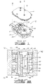
- Fig. 1 is a partially exploded perspective view of a prior art disc drive of the type in which the present invention is particularly useful.
- Fig. 2 is a partially sectional elevation view of a typical prior art pivot mechanism.
- Fig. 3 is a partially sectional elevation view of another pivot mechanism from the prior art.
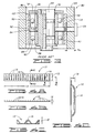
- Figs. 4A, 4B, 4C and 4D are plan, elevation, longitudinal sectional and lateral sectional views, respectively, of a tolerance ring component of an embodiment of the present invention.
- Fig. 5 is a partially sectional elevation view of a pivot mechanism constructed in accordance with an embodiment of the present invention.
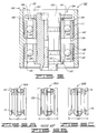
- Figs. 6A, 6B and 6C are diagrammatical representations of three pivot mechanisms, one from the prior art and two embodiments of the present invention, all drawn to the same scale to illustrate the dimensional advantages of the present invention.
- Figs. 4A through 4D are several views of a tolerance ring 110 forming a part of the present invention.
- the tolerance ring strip 110 is formed from steel grip material which is shaped into a ring upon assembly into the pivot mechanism of the present invention. Typical material thickness is about 1.27 x 10 -4 m (.005 inch).
- the width 112 of the tolerance ring 110 is approximately the same as the width of the outer race of the bearings shown in Fig. 5, and the length 113 of the tolerance ring 110 is slightly shorter than the outer circumference of the ball bearing assembly of Fig. 5.
- parallel raised contact surfaces 114 are formed to a height 116 of typically about 3.3 x 10 -4 m (.013 inch) in the tolerance ring 100.
- the shape of the raised contact surfaces 114 and the thinness of the material make the contact surfaces 114 relatively compliant in the axis defined by arrow 118 in Fig. 4C. The significance of this compliance will become evident in the following discussion.
- the tolerance ring 110 is available commercially from USA Tolerance Ring Corporation of West Trenton, New Jersey; a typical model of such is ANL 12.7X5S.
- Fig. 5 shows a pivot mechanism 120 made in accordance with the present invention.
- the pivot mechanism 120 is similar in construction to the pivot mechanisms discussed above except as described hereinafter, and includes a pivot shaft 122, a lower ball bearing assembly 124, an upper ball bearing assembly 126 and an actuator body 128, with each of the ball bearing assemblies 124, 126 including a plurality of balls 129. Preloading of the ball bearing assemblies 124, 126 is accomplished using a spring washer 130 and a fixed ring or clip 132 as previously explained.
- the actuator body 128 includes a central bore 134 having upper and lower portions of a slightly larger diameter, and a narrow section 136 of reduced diameter at approximately the midpoint of the central bore 134.
- a lower surface 138 and an upper surface 140 of this narrow section 136 provide contact surfaces for lower outer race 142 and upper outer race 144 of the ball bearing assemblies 124, 126, respectively.
- a pair of tolerance rings 110 described in the discussion of FIGS. 4A-4D above, are provided and are located between the outer surfaces of the outer races 142, 144 and the inner surface of the central bore 134 in the actuator body 128.
- Assembly of the pivot mechanism 120 preferably is accomplished in the following order:
- step 1.6 testing of the assembled unit may be done after step 1.6 above. If such testing reveals the failure of any of the components or the assembly process, the actuator body 128, by far the most expensive component in the assembly, can be readily separated and reused, thus greatly reducing the value of scrapped parts and lowering the average cost of the entire disc drive unit.
- the tolerance rings 110 are installed in the central bore 134 of the actuator body 128 with the raised contact surfaces 114 toward the outer races 142, 144 of the bearing assemblies 124, 126. This orientation distributes the force generated by pressing the bearing assemblies 124, 126 into the actuator body 128 across a relatively large area on the actuator body 128 and a relatively small area on the outer races 142, 144 of the bearing assemblies 124, 126. Since the outer races 142, 144 and the tolerance rings 110 are steel, and the actuator body 128 is preferably aluminum or magnesium, this minimizes the risk of damaging the relatively soft central bore 134 of the actuator body 128.
- the thickness of the wall of the actuator body 128, designated as 158 therein is relatively thinner than that shown in the prior art examples of FIGS. 2 and 3 above.
- the stresses imposed by differential thermal expansion and contraction will be compensated for and absorbed by the compliance of the tolerance rings 110 noted above in the discussion of FIGS. 4A-4D. This in turn allows the outer diameter of the actuator body 128 to be reduced, resulting in a more compact rotary actuator assembly with the same size ball bearing assemblies.
- FIGS. 6A-6C One significant advantage of the present invention is best shown diagrammatically in FIGS. 6A-6C, wherein three pivot mechanisms are drawn to the same scale.
- FIG. 6B illustrates a prior art pivot mechanism 80A similar to that discussed in relation to FIG. 3 above, i.e., a pivot mechanism including a bearing cartridge subassembly.
- FIGS. 6A and 6C show alternative embodiments 120A and 120B, respectively, of the pivot mechanism of the present invention.
- a comparison of FIG. 6B to FIG. 6A shows that both pivot mechanisms 80A and 120A use ball bearing assemblies of the same size, but that the pivot mechanism 120A of FIG. 6A has a significantly smaller outer diameter (OD) due to the implementation of the present invention, making the pivot mechanism 120A suitable for use in disc drives of smaller form factors.
- OD outer diameter
- the compliance of the tolerance rings 110 allows for the loosening of the machining tolerance on the central bore 134 of the actuator body 128.
- the diameter of the central bore 134 in the pivot mechanism 120 of the present invention need only be held within about +2.54 x 10 -5 m (+0.001 inch) tolerance instead of a much tighter +2.54 x 10 -6 m (+0.0001 inch) tolerance, thus reducing the cost of the pivot mechanism and the entire disc drive.
- the radial stiffness of the tolerance rings 110 is great enough that in-plane vibration modes of the head mounting arms supported by the actuator body are not degraded.
- the natural frequency of the pivot mechanism rose due to the lower moving mass of the present invention.
- the smaller moving mass of the pivot mechanism of the present invention produces faster access times, improving the data handling performance of the disc drive assembly.
Landscapes
- Engineering & Computer Science (AREA)
- General Engineering & Computer Science (AREA)
- Mechanical Engineering (AREA)
- Moving Of Heads (AREA)
- Support Of The Bearing (AREA)
Claims (10)
- Schwenkmechanismus (120;120A;120B) für ein Drehstellglied in einem Plattenlaufwerk (10), mit:einer Schwenkwelle (122) zur Befestigung des Schwenkmechanismus an dem Plattenlaufwerk;oberen und unteren Kugellagerbaugruppen (124,126), die jeweils einen Lagerinnenring (150,154) und einen Lageraußenring (142,144) mit einer zwischen diesen festgelegten Kugellagerung (129) aufweisen, wobei die Lagerinnenringe mit der Schwenkwelle in Eingriff stehen;einen Stellgliedkörper (128) mit einer Mittelbohrung (134) zum Koppeln eines Motors mit einem oder mehreren Lese-/Schreibköpfen des Plattenlaufwerks, undAbstandseinrichtungen (136,138,140), die die Lageraußenringe bezüglich des Stellgliedkörpers in axialem Abstand voneinander halten,gekennzeichnet durch:
erste und zweite Toleranzringe (110), die zwischen den Lageraußenringen (142,144) beider Kugellagerbaugruppen und der Mittelbohrung des Stellgliedkörpers angeordnet sind. - Schwenkmechanismus nach Anspruch 1,
bei dem die axiale Abstandseinrichtung
einen Abschnitt (136) mit verringertem Durchmesser in der Mittelbohrung (134) umfaßt, an dem die Lageraußenringe der Kugellagerbaugruppen anliegen. - Schwenkmechanismus nach Anspruch 1 oder 2,
bei dem die axiale Abstandseinrichtung weiterhin eine Schulter (152) auf der Schwenkwelle einschließt, gegen die der Lagerinnenring der unteren Kugellagerbaugruppe anliegt. - Schwenkmechanismus nach Anspruch 1, 2 oder 3,
der Vorspanneinrichtungen (130,132) zum Vorspannen der Lagerinnenringe in Richtung aufeinander entlang der Länge der Schwenkwelle und zur Vorspannung der Lageraußenringe voneinander fort im Inneren der Mittelbohrung des Stellgliedkörpers umfaßt. - Schwenkmechanismus nach Anspruch 4,
bei dem die Vorspanneinrichtungenein Halteteil (132), das am oberen Ende der Schwenkwelle befestigt ist, undein elastisches Element (130) umfassen, das zwischen dem Halteteil und dem Lagerinnenring der oberen Kugellagerbaugruppe in Richtung auf den Lagerinnenring des unteren Kugellagers angeordnet ist. - Schwenkmechanismus nach einem der vorhergehenden Ansprüche, mit Befestigungseinrichtungen zur Befestigung der Lagerinnenringe an der Schwenkwelle, wobei die Befestigungseinrichtungen ein Klebemittel zum Verbinden des Lagerinnenringes des oberen Kugellagers mit der Schwenkwelle umfassen.
- Verfahren zur Herstellung eines Schwenkmechanismus (120; 120A;120B) für ein Drehstellglied in einem Plattenlaufwerk (10), das folgende Schritte einschließt:(a) Ausbildung einer Schwenkwelle (122) mit einer Schulter (152) mit einem größeren Durchmesser als der Rest der Schwenkwelle, eng benachbart zu deren unterem Ende, und(b) Ausbildung eines Stellgliedkörpers (128) mit einer Mittelbohrung (134),gekennzeichnet durch:
die Ausbildung des Stellgliedkörpers (128) mit einer Mittelbohrung (134), die einen schmalen Abschnitt (136) mit verringertem Durchmesser an einem Mittelteil des Stellgliedkörpers aufweist,
und dadurch, daß das Verfahren weiterhin die folgenden Schritte umfaßt:(c) Befestigung von oberen und unteren Toleranzringen (110) in der Mittelbohrung oberhalb bzw. unterhalb des schmalen Abschnittes;(d) Aufbringen einer unteren Kugellagerbaugruppe (124) mit einem Lagerinnenring (150) und einem Lageraußenring (142) auf die Schwenkwelle derart, daß der Lagerinnenring gegen die Schulter der Schwenkwelle anliegt;(e) Einpressen der unteren, auf der Schwenkwelle gehalterten Kugellagerbaugruppe in die Mittelbohrung unterhalb des schmalen Abschnittes, bis der Lageraußenring der unteren Kugellagerbaugruppe gegen die untere Oberfläche des schmalen Abschnittes anliegt, wodurch der untere Toleranzring zwischen dem Lageraußenring der unteren Kugellagerbaugruppe und der Innenoberfläche des Stellgliedkörpers komprimiert wird;(f) Aufbringen einer oberen Kugellagerbaugruppe (126) mit einem Lagerinnenring (154) und einem Lageraußenring (144) auf die Schwenkwelle und in die Mittelbohrung, bis der Lageraußenring der oberen Kugellagerbaugruppe gegen die obere Oberfläche des schmalen Abschnittes anliegt, wodurch der obere Toleranzring zwischen dem Lageraußenring der oberen Kugellagerbaugruppe und der Innenoberfläche des Stellgliedkörpers komprimiert wird; und(g) Vorspannen des Lagerinnenringes der oberen Kugellagerbaugruppe in Richtung auf die untere Kugellagerbaugruppe. - Verfahren nach Anspruch 7,
das weiterhin den Schritt des:
(h) Aufbringens eines Klebemittels auf den Lagerinnenring der oberen Kugellagerbaugruppe vor dem Schritt (f) derart umfaßt, daß der Lagerinnenring des oberen Kugellagers mit der Schwenkwelle verbunden wird, nachdem der Schritt (d) abgeschlossen wurde. - Verfahren nach Anspruch 8,
bei dem der Schritt (g) dasAufbringen einer Vorspannkraft auf die obere Oberfläche des Lagerinnenringes der oberen Kugellagerbaugruppe; unddas Aufrechterhalten der Vorspannkraft auf den Lagerinnenring der oberen Kugellagerbaugruppe umfaßt, bis die Klebemittelverbindung des Schrittes (h) abgeschlossen ist. - Verfahren nach Anspruch 8,
bei dem der Schritt (g)das Aufbringen eines elastischen Elementes (130) auf die Schwenkwelle zum Drücken gegen den Lagerinnenring der oberen Kugellagerbaugruppe; unddie Befestigung eines Halteteils (132) in der Nähe des oberen Endes der Schwenkwelle derart umfaßt, daß das elastische Element zwischen dem Halteteil und dem Lagerinnenring der oberen Kugellagerbaugruppe komprimiert wird, um auf diese Weise eine Vorspannkraft auf die oberen und unteren Kugellagerbaugruppen auszuüben.
Applications Claiming Priority (2)
| Application Number | Priority Date | Filing Date | Title |
|---|---|---|---|
| US729453 | 1991-07-12 | ||
| US07/729,453 US5315465A (en) | 1991-07-12 | 1991-07-12 | Compliant pivot mechanism for a rotary actuator |
Publications (3)
| Publication Number | Publication Date |
|---|---|
| EP0522717A2 EP0522717A2 (de) | 1993-01-13 |
| EP0522717A3 EP0522717A3 (en) | 1993-03-31 |
| EP0522717B1 true EP0522717B1 (de) | 1997-08-06 |
Family
ID=24931102
Family Applications (1)
| Application Number | Title | Priority Date | Filing Date |
|---|---|---|---|
| EP92305463A Expired - Lifetime EP0522717B1 (de) | 1991-07-12 | 1992-06-15 | Drehmechanismus für einen rotierenden Kopfantrieb |
Country Status (5)
| Country | Link |
|---|---|
| US (1) | US5315465A (de) |
| EP (1) | EP0522717B1 (de) |
| JP (1) | JP3042188B2 (de) |
| DE (1) | DE69221401T2 (de) |
| SG (1) | SG48783A1 (de) |
Cited By (1)
| Publication number | Priority date | Publication date | Assignee | Title |
|---|---|---|---|---|
| SG128410A1 (en) * | 2000-08-23 | 2007-01-30 | Seagate Technology Llc | Actuator pivot assembly |
Families Citing this family (51)
| Publication number | Priority date | Publication date | Assignee | Title |
|---|---|---|---|---|
| US4979063A (en) * | 1986-10-02 | 1990-12-18 | Seagate Technology, Inc. | Design for an actuator arm for a disc drive |
| JP2671738B2 (ja) * | 1992-11-30 | 1997-10-29 | 日本電気株式会社 | 磁気ディスク装置 |
| JP2675986B2 (ja) * | 1994-02-18 | 1997-11-12 | インターナショナル・ビジネス・マシーンズ・コーポレイション | 複合アクチュエータベアリングシステムを有する直接アクセス記憶装置及びその方法 |
| US5548458A (en) * | 1994-05-04 | 1996-08-20 | Seagate Technology, Inc. | Support flange having electrical contacts to provide electrical continuity upon spindle motor mounting to base |
| US5482381A (en) * | 1994-06-16 | 1996-01-09 | Seagate Technology, Inc. | Actuator assembly having labyrinth seal |
| US5835309A (en) * | 1995-05-22 | 1998-11-10 | International Business Machines Corporation | Pivot bearing |
| US5659443A (en) * | 1995-12-01 | 1997-08-19 | International Business Machines Corporation | Split band retainer for radially clamping a disk to a hub in a disk drive |
| US6163441A (en) * | 1998-02-24 | 2000-12-19 | Seagate Technology Llc | Resonance dampening actuator bearing assembly |
| US6603634B1 (en) | 1998-06-05 | 2003-08-05 | Seagate Technology Llc | Compressive spring sleeve for reducing disc slippage |
| US6288879B1 (en) * | 1998-09-25 | 2001-09-11 | Seagate Technolocy Llc | Top down assembly of a disk drive actuator using a tolerance ring and a post |
| US6342992B1 (en) | 1999-08-13 | 2002-01-29 | International Business Machines Corporation | Hard disk drive actuator pivot with inboard pads and enhanced pivot sleeve thickness for improved servo stability |
| DE10085247T1 (de) * | 1999-12-03 | 2002-11-07 | Seagate Technology Llc | Toleranzring mit konsistentem niedrigem Einbaukraftprofil |
| US6422080B1 (en) | 2000-02-07 | 2002-07-23 | Seagate Technology Llc | Resonance control method for a disc drive actuator assembly having discrete bearings |
| CN1433509A (zh) * | 2000-02-09 | 2003-07-30 | 西加特技术有限责任公司 | 具有高的箍强度以抵制变形的公差配合环 |
| US6901598B1 (en) * | 2000-04-24 | 2005-05-31 | Dphi Acquisitions, Inc. | Tilt focus method and mechanism for an optical drive |
| US6480363B1 (en) | 2000-05-22 | 2002-11-12 | International Business Machines Corporation | Hard disk drive actuator assembly with damped tolerance ring for enhancing drive performance during structural resonance modes |
| JP3536022B2 (ja) * | 2000-10-04 | 2004-06-07 | ミネベア株式会社 | ピボット軸受装置 |
| US6519116B1 (en) * | 2000-11-30 | 2003-02-11 | Western Digital Technologies, Inc. | Actuator arm assembly having bearing gap formed between bearing outer race and pivot sleeve for mitigating torque ripple on actuator arm in a disk drive |
| US6687092B2 (en) | 2001-05-10 | 2004-02-03 | Hitachi Global Storage Technologies Netherland B.V. | Pivot bearing assembly for compensating for disk drive actuator tilt |
| US6618226B2 (en) | 2001-07-10 | 2003-09-09 | International Business Machines Corporation | Locally deformable sleeve on disk drive pivot assembly |
| JP3995490B2 (ja) | 2002-02-05 | 2007-10-24 | ミネベア株式会社 | ピボットアッシー及びその製造方法 |
| US7085108B1 (en) | 2002-09-30 | 2006-08-01 | Western Digital Technologies, Inc. | Disk drive including pivot-bearing cartridge tolerance ring having a damping layer for actuator resonance reduction |
| JP3868361B2 (ja) * | 2002-10-04 | 2007-01-17 | 株式会社日立製作所 | 塑性流動結合体とその結合方法 |
| US7054111B2 (en) * | 2002-11-18 | 2006-05-30 | Hitachi Global Storage Technologies Netherlands B.V. | Disk drive actuator-pivot assembly with corrugated rings |
| US7007386B1 (en) | 2002-12-20 | 2006-03-07 | General Sullivan Group, Inc. | Light duty bearing assembly |
| GB0308957D0 (en) | 2003-04-17 | 2003-05-28 | Lillishall Plastics And Engine | Tolerance ring assembly |
| US20040246627A1 (en) * | 2003-06-06 | 2004-12-09 | Durrum Thomas M. | Disc drive pivot bearing assembly |
| JP2005276291A (ja) | 2004-03-24 | 2005-10-06 | Hitachi Global Storage Technologies Netherlands Bv | 回転円板形記憶装置及びピボット軸受アセンブリ |
| US7379273B2 (en) * | 2004-05-10 | 2008-05-27 | Seagate Technology Llc | Anti-gall bearing with captive screw |
| GB0425856D0 (en) * | 2004-11-24 | 2004-12-29 | Rencol Tolerance Rings Ltd | Fixing of components |
| US8363358B2 (en) * | 2008-08-15 | 2013-01-29 | Hgst, Netherlands B.V. | Pivot-carriage having a center-bore with an integrated bearing-spacer portion |
| WO2010029429A1 (en) | 2008-09-10 | 2010-03-18 | Saint-Gobain Performance Plastics Rencol Limited | Tolerance ring and mounting assembly with such a tolerance ring |
| JP5607978B2 (ja) | 2010-04-08 | 2014-10-15 | ミネベア株式会社 | ピボットアッシー軸受 |
| US8579514B2 (en) | 2010-04-26 | 2013-11-12 | Seagate Technology Llc | Press fitting a cartridge bearing |
| US8416534B1 (en) | 2010-06-30 | 2013-04-09 | Western Digital Technologies, Inc. | Disk drive with asymmetric tolerance ring |
| JP5474710B2 (ja) * | 2010-09-03 | 2014-04-16 | 株式会社東郷製作所 | トルク伝達装置用トレランスリング |
| WO2012144628A1 (ja) | 2011-04-22 | 2012-10-26 | 日本発條株式会社 | トレランスリングおよびトレランスリングの製造方法 |
| JP2013103696A (ja) * | 2011-11-16 | 2013-05-30 | Jtekt Corp | 電動パワーステアリング装置 |
| US9255609B2 (en) | 2011-12-09 | 2016-02-09 | Nhk Spring Co., Ltd. | Tolerance ring, hard disk device, and method for manufacturing hard disk device |
| US9019663B2 (en) | 2011-12-28 | 2015-04-28 | Nhk Spring Co., Ltd. | Tolerance ring |
| US9829046B2 (en) | 2012-02-17 | 2017-11-28 | Nhk Spring Co., Ltd. | Tolerance ring |
| JP5928088B2 (ja) * | 2012-03-29 | 2016-06-01 | 日本精工株式会社 | 磁気記録装置のスイングアーム用ピボット軸受け装置およびこれを用いた磁気記録装置 |
| WO2015080276A1 (ja) | 2013-11-29 | 2015-06-04 | 日本発條株式会社 | トレランスリングおよびハードディスク装置 |
| US10157635B2 (en) | 2014-07-11 | 2018-12-18 | Saint-Gobain Performance Plastics Rencol Limited | Stepped assembly |
| US9293162B1 (en) * | 2014-09-09 | 2016-03-22 | HGST Netherlands B.V. | Actuator comb having a stepped inner bore |
| US9620155B2 (en) | 2015-07-23 | 2017-04-11 | Seagate Technology Llc | Disc drive actuator bearing cartridge assembly with temperature induced rotational torque mitigation |
| JP6263157B2 (ja) | 2015-09-17 | 2018-01-17 | ミネベアミツミ株式会社 | ハードディスク駆動装置及びピボットアッシー軸受装置 |
| US20160076590A1 (en) * | 2015-11-24 | 2016-03-17 | Schaeffler Technologies AG & Co. KG | Ball bearing with slanted or angled flat raceways |
| WO2017145345A1 (ja) * | 2016-02-25 | 2017-08-31 | 日本精工株式会社 | センサ |
| CN110953254A (zh) * | 2018-09-27 | 2020-04-03 | 北京自动化控制设备研究所 | 一种轴向预紧可调舵机输出轴机构 |
| CN109538638B (zh) * | 2018-12-14 | 2024-07-02 | 宁波达尔机械科技有限公司 | 高速转子及其装配方法 |
Family Cites Families (20)
| Publication number | Priority date | Publication date | Assignee | Title |
|---|---|---|---|---|
| US3269204A (en) * | 1964-01-06 | 1966-08-30 | Gen Electric | Gear motors and gearing units therefor |
| US3626743A (en) * | 1969-12-22 | 1971-12-14 | Roller Bearing Co | Making corrugated elastic shims |
| US3633398A (en) * | 1970-01-21 | 1972-01-11 | Roller Bearing Co Of America | Making corrugated elastic shims |
| DE2018367B1 (de) * | 1970-04-16 | 1971-07-29 | Deutsche Star Kugelhalter Gmbh, 8720 Schweinfurt | Verbindungselement fur eine Kupplung mit Klemmbuchse zum Befestigen einer Nabe auf einer Welle |
| US3776653A (en) * | 1971-10-20 | 1973-12-04 | Roller Bearing Co Of America | Corrugated elastic shim and shaft and hub |
| IT984360B (it) * | 1972-03-06 | 1974-11-20 | Star Kugelhalter Gmbh Dt | Elemento di inserto interponibile tra organi di macchine a scopo di collegamento |
| US4286894A (en) * | 1979-03-21 | 1981-09-01 | Roller Bearing Company Of America | Tolerance rings |
| JPS58153275A (ja) * | 1982-03-08 | 1983-09-12 | Nec Corp | 磁気デイスク装置の位置決め機構 |
| JPS5963872U (ja) * | 1982-10-20 | 1984-04-26 | トキコ株式会社 | 磁気デイスク装置 |
| JPS62149075A (ja) * | 1985-12-23 | 1987-07-03 | Hitachi Ltd | 磁気デイスク装置 |
| US4716483A (en) * | 1986-02-14 | 1987-12-29 | Hewlett-Packard Company | Three piece head actuator arm assembly for disc drive |
| EP0432145B1 (de) * | 1986-06-04 | 1994-03-16 | Fujitsu Limited | Magnet-Scheibengerät |
| US4995025A (en) * | 1986-10-06 | 1991-02-19 | Schulze Dieter M | Spherical pivoting actuator for read/record head |
| AU1358188A (en) * | 1987-03-30 | 1988-09-29 | Seagate Technology, Inc. | Bi-compliant rotor stepper motor for an actuator in disc drives |
| US4896239A (en) * | 1987-03-30 | 1990-01-23 | Seagate Technology, Inc. | Bi-compliant rotor stepper motor for an actuator in a disc drive |
| US4828423A (en) * | 1987-04-06 | 1989-05-09 | Cramer Jr Arthur A | Tolerance ring and shim |
| JPS6457463A (en) * | 1987-08-28 | 1989-03-03 | Nippon Telegraph & Telephone | Actuator for head of magnetic disk device |
| US4790683A (en) * | 1987-10-05 | 1988-12-13 | Cramer Jr Arthur A | Tolerance ring and shim and method of use |
| US4888656A (en) * | 1988-07-18 | 1989-12-19 | Seagate Technology, Inc. | Pivot mechanism for rotary disc drives |
| US4893206A (en) * | 1988-07-28 | 1990-01-09 | Eastman Kodak Company | Pivoting radial access mechanism with spinning support shaft |
-
1991
- 1991-07-12 US US07/729,453 patent/US5315465A/en not_active Expired - Fee Related
-
1992
- 1992-06-15 EP EP92305463A patent/EP0522717B1/de not_active Expired - Lifetime
- 1992-06-15 DE DE69221401T patent/DE69221401T2/de not_active Expired - Fee Related
- 1992-06-15 SG SG1996001621A patent/SG48783A1/en unknown
- 1992-07-09 JP JP4182464A patent/JP3042188B2/ja not_active Expired - Fee Related
Cited By (1)
| Publication number | Priority date | Publication date | Assignee | Title |
|---|---|---|---|---|
| SG128410A1 (en) * | 2000-08-23 | 2007-01-30 | Seagate Technology Llc | Actuator pivot assembly |
Also Published As
| Publication number | Publication date |
|---|---|
| US5315465A (en) | 1994-05-24 |
| DE69221401D1 (de) | 1997-09-11 |
| JP3042188B2 (ja) | 2000-05-15 |
| EP0522717A3 (en) | 1993-03-31 |
| DE69221401T2 (de) | 1997-12-11 |
| SG48783A1 (en) | 1998-05-18 |
| JPH05205413A (ja) | 1993-08-13 |
| EP0522717A2 (de) | 1993-01-13 |
Similar Documents
| Publication | Publication Date | Title |
|---|---|---|
| EP0522717B1 (de) | Drehmechanismus für einen rotierenden Kopfantrieb | |
| US6606224B2 (en) | Cartridge bearing with frictional sleeve | |
| US5590004A (en) | Resilient clamp and compliant element data disk support system | |
| US6480363B1 (en) | Hard disk drive actuator assembly with damped tolerance ring for enhancing drive performance during structural resonance modes | |
| US5539597A (en) | Press-fit glueless bearing pivot assembly for a rotary actuator | |
| US6603636B2 (en) | Apparatus for centering a disc clamp on a disc pack in a disc drive | |
| JP2763680B2 (ja) | 高壁ディスククランプ | |
| US6175469B1 (en) | Disc drive magnet housing electro mechanical resonance dampening system | |
| US6128164A (en) | Baseplate design for the arm and suspension assembly for minimal gram-force and z-height variation | |
| US5486961A (en) | Resilient compliant clamp for data storage disk drives | |
| US6288879B1 (en) | Top down assembly of a disk drive actuator using a tolerance ring and a post | |
| US6651340B2 (en) | Self-aligning fixture for pre-loading and aligning pivot bearing assemblies | |
| US6462902B1 (en) | Independent clamping spacers in a disc drive assembly | |
| US6212029B1 (en) | Snubber for a disc drive | |
| KR100433865B1 (ko) | 스핀들 모터 어셈블리 및 디스크 드라이브 내에 정보 저장 디스크를 고정하는 방법 | |
| US6788495B2 (en) | Disc pack assembly | |
| US20040246627A1 (en) | Disc drive pivot bearing assembly | |
| US5864449A (en) | Precision limit stop for high density disk drives | |
| US6603634B1 (en) | Compressive spring sleeve for reducing disc slippage | |
| US5768060A (en) | Low pofile radially and axially preloaded ball bearing for actuator pivot | |
| US6038105A (en) | Temperature-compensated rotary actuator cartridge bearing stablizer | |
| JP3758757B2 (ja) | ディスク装置 | |
| US4888656A (en) | Pivot mechanism for rotary disc drives | |
| US6113277A (en) | Actuator pivot bearing with reduced hysteresis | |
| JPH04184758A (ja) | ディスク駆動装置 |
Legal Events
| Date | Code | Title | Description |
|---|---|---|---|
| PUAI | Public reference made under article 153(3) epc to a published international application that has entered the european phase |
Free format text: ORIGINAL CODE: 0009012 |
|
| AK | Designated contracting states |
Kind code of ref document: A2 Designated state(s): DE FR GB IT |
|
| PUAL | Search report despatched |
Free format text: ORIGINAL CODE: 0009013 |
|
| AK | Designated contracting states |
Kind code of ref document: A3 Designated state(s): DE FR GB IT |
|
| 17P | Request for examination filed |
Effective date: 19930610 |
|
| 17Q | First examination report despatched |
Effective date: 19951002 |
|
| GRAG | Despatch of communication of intention to grant |
Free format text: ORIGINAL CODE: EPIDOS AGRA |
|
| GRAH | Despatch of communication of intention to grant a patent |
Free format text: ORIGINAL CODE: EPIDOS IGRA |
|
| GRAH | Despatch of communication of intention to grant a patent |
Free format text: ORIGINAL CODE: EPIDOS IGRA |
|
| GRAA | (expected) grant |
Free format text: ORIGINAL CODE: 0009210 |
|
| AK | Designated contracting states |
Kind code of ref document: B1 Designated state(s): DE FR GB IT |
|
| PG25 | Lapsed in a contracting state [announced via postgrant information from national office to epo] |
Ref country code: IT Free format text: LAPSE BECAUSE OF FAILURE TO SUBMIT A TRANSLATION OF THE DESCRIPTION OR TO PAY THE FEE WITHIN THE PRE;WARNING: LAPSES OF ITALIAN PATENTS WITH EFFECTIVE DATE BEFORE 2007 MAY HAVE OCCURRED AT ANY TIME BEFORE 2007. THE CORRECT EFFECTIVE DATE MAY BE DIFFERENT FROM THE ONE RECORDED.SCRIBED TIME-LIMIT Effective date: 19970806 Ref country code: FR Free format text: LAPSE BECAUSE OF FAILURE TO SUBMIT A TRANSLATION OF THE DESCRIPTION OR TO PAY THE FEE WITHIN THE PRESCRIBED TIME-LIMIT Effective date: 19970806 |
|
| REF | Corresponds to: |
Ref document number: 69221401 Country of ref document: DE Date of ref document: 19970911 |
|
| EN | Fr: translation not filed | ||
| PLBE | No opposition filed within time limit |
Free format text: ORIGINAL CODE: 0009261 |
|
| STAA | Information on the status of an ep patent application or granted ep patent |
Free format text: STATUS: NO OPPOSITION FILED WITHIN TIME LIMIT |
|
| 26N | No opposition filed | ||
| REG | Reference to a national code |
Ref country code: GB Ref legal event code: 732E |
|
| PGFP | Annual fee paid to national office [announced via postgrant information from national office to epo] |
Ref country code: GB Payment date: 20010510 Year of fee payment: 10 |
|
| PGFP | Annual fee paid to national office [announced via postgrant information from national office to epo] |
Ref country code: DE Payment date: 20010607 Year of fee payment: 10 |
|
| REG | Reference to a national code |
Ref country code: GB Ref legal event code: IF02 |
|
| PG25 | Lapsed in a contracting state [announced via postgrant information from national office to epo] |
Ref country code: GB Free format text: LAPSE BECAUSE OF NON-PAYMENT OF DUE FEES Effective date: 20020615 |
|
| PG25 | Lapsed in a contracting state [announced via postgrant information from national office to epo] |
Ref country code: DE Free format text: LAPSE BECAUSE OF NON-PAYMENT OF DUE FEES Effective date: 20030101 |
|
| GBPC | Gb: european patent ceased through non-payment of renewal fee |
Effective date: 20020615 |