EP0522718A2 - Amortisseur de vibrations torsionnelles - Google Patents
Amortisseur de vibrations torsionnelles Download PDFInfo
- Publication number
- EP0522718A2 EP0522718A2 EP92305485A EP92305485A EP0522718A2 EP 0522718 A2 EP0522718 A2 EP 0522718A2 EP 92305485 A EP92305485 A EP 92305485A EP 92305485 A EP92305485 A EP 92305485A EP 0522718 A2 EP0522718 A2 EP 0522718A2
- Authority
- EP
- European Patent Office
- Prior art keywords
- coil
- spring
- wire
- thickness
- coils
- Prior art date
- Legal status (The legal status is an assumption and is not a legal conclusion. Google has not performed a legal analysis and makes no representation as to the accuracy of the status listed.)
- Granted
Links
- 230000007704 transition Effects 0.000 claims description 7
- 238000004519 manufacturing process Methods 0.000 claims description 5
- 230000000712 assembly Effects 0.000 claims 6
- 238000000429 assembly Methods 0.000 claims 6
- 239000007787 solid Substances 0.000 description 5
- 230000035939 shock Effects 0.000 description 4
- 238000005452 bending Methods 0.000 description 3
- 230000005540 biological transmission Effects 0.000 description 3
- 238000006073 displacement reaction Methods 0.000 description 2
- 238000010521 absorption reaction Methods 0.000 description 1
- 230000006835 compression Effects 0.000 description 1
- 238000007906 compression Methods 0.000 description 1
- 238000010276 construction Methods 0.000 description 1
- 238000013016 damping Methods 0.000 description 1
- 239000013013 elastic material Substances 0.000 description 1
- 239000000463 material Substances 0.000 description 1
- 230000004048 modification Effects 0.000 description 1
- 238000012986 modification Methods 0.000 description 1
- 238000004806 packaging method and process Methods 0.000 description 1
- 238000005096 rolling process Methods 0.000 description 1
Images



Classifications
-
- F—MECHANICAL ENGINEERING; LIGHTING; HEATING; WEAPONS; BLASTING
- F16—ENGINEERING ELEMENTS AND UNITS; GENERAL MEASURES FOR PRODUCING AND MAINTAINING EFFECTIVE FUNCTIONING OF MACHINES OR INSTALLATIONS; THERMAL INSULATION IN GENERAL
- F16F—SPRINGS; SHOCK-ABSORBERS; MEANS FOR DAMPING VIBRATION
- F16F1/00—Springs
- F16F1/02—Springs made of steel or other material having low internal friction; Wound, torsion, leaf, cup, ring or the like springs, the material of the spring not being relevant
- F16F1/04—Wound springs
- F16F1/06—Wound springs with turns lying in cylindrical surfaces
-
- F—MECHANICAL ENGINEERING; LIGHTING; HEATING; WEAPONS; BLASTING
- F16—ENGINEERING ELEMENTS AND UNITS; GENERAL MEASURES FOR PRODUCING AND MAINTAINING EFFECTIVE FUNCTIONING OF MACHINES OR INSTALLATIONS; THERMAL INSULATION IN GENERAL
- F16F—SPRINGS; SHOCK-ABSORBERS; MEANS FOR DAMPING VIBRATION
- F16F15/00—Suppression of vibrations in systems; Means or arrangements for avoiding or reducing out-of-balance forces, e.g. due to motion
- F16F15/10—Suppression of vibrations in rotating systems by making use of members moving with the system
- F16F15/12—Suppression of vibrations in rotating systems by making use of members moving with the system using elastic members or friction-damping members, e.g. between a rotating shaft and a gyratory mass mounted thereon
- F16F15/121—Suppression of vibrations in rotating systems by making use of members moving with the system using elastic members or friction-damping members, e.g. between a rotating shaft and a gyratory mass mounted thereon using springs as elastic members, e.g. metallic springs
- F16F15/123—Wound springs
- F16F15/12313—Wound springs characterised by the dimension or shape of spring-containing windows
-
- F—MECHANICAL ENGINEERING; LIGHTING; HEATING; WEAPONS; BLASTING
- F16—ENGINEERING ELEMENTS AND UNITS; GENERAL MEASURES FOR PRODUCING AND MAINTAINING EFFECTIVE FUNCTIONING OF MACHINES OR INSTALLATIONS; THERMAL INSULATION IN GENERAL
- F16F—SPRINGS; SHOCK-ABSORBERS; MEANS FOR DAMPING VIBRATION
- F16F15/00—Suppression of vibrations in systems; Means or arrangements for avoiding or reducing out-of-balance forces, e.g. due to motion
- F16F15/10—Suppression of vibrations in rotating systems by making use of members moving with the system
- F16F15/12—Suppression of vibrations in rotating systems by making use of members moving with the system using elastic members or friction-damping members, e.g. between a rotating shaft and a gyratory mass mounted thereon
- F16F15/121—Suppression of vibrations in rotating systems by making use of members moving with the system using elastic members or friction-damping members, e.g. between a rotating shaft and a gyratory mass mounted thereon using springs as elastic members, e.g. metallic springs
- F16F15/123—Wound springs
- F16F15/1232—Wound springs characterised by the spring mounting
Definitions
- This invention relates to improvements in automotive torsional vibration dampers and more particularly to an improved helical torsion spring for use in a torsional vibration damper.
- vibration dampers Conventionly has been an accepted way to absorb undesirable torsional vibrations from the vehicle engine or transmission input during operation of a motor vehicle.
- vibration dampers have been designed with springs in parallel and in series with a capacity to absorb torsional shock or vibration emanating from an engine or transmission input without the spring in the vibration damper being fully compressed to its solid height.
- the vibration dampers had to absorb increased torsional loads and the springs in the vibration dampers compressed to a greater extent to absorb the increased loads.
- torsional vibration dampers Due to packaging constraints, the torsional vibration dampers increased capacity must be achieved without an increase in size. Hence, what is needed is a torsional vibration damper that has its springs designed to be durable and to be fully compressed thereby maximizing the capacity for vibration absorption and eliminating the necessity for a separate limit stop built into the torsional vibration damper.
- a spring has been defined as a machine element for storing energy as a function of displacement. Force applied to a spring member causes it to deflect through a certain displacement thus absorbing energy.
- a spring may have any shape and may be formed from any elastic material.
- coil springs are commonly utilized in damping arrangements in clutch plates and torsional dampers.
- the springs in the damper provide vibration control by reducing stiffness of a drive line. Additional spring wire stressed in torsion lowers the drive line stiffness. Thus, the springs, by lowering the stiffness of the drive line, provide vibration control from impulses or shocks in the driveline of an automotive vehicle between the vehicle engine and the transmission.
- a helical spring is formed from a bar or wire, commonly with uniform cross section, which is wound in a helix.
- the last turn at each end of the spring is modified to have a planar end surface lying in a plane perpendicular to the helix axis, and force can then be applied to the bearing surfaces of the end coils to place the helix in compression.
- Springs may be classified into several varieties with the variation in the end coil providing the difference.
- a plain end for a coil spring has a constant pitch for both the active coils and the end coils with the wire cut off generally square to the axis of the wire.
- the end coils can then be ground square to the spring axis, providing flat bearing surfaces.
- a closed end spring has the final coil bent so that at least a portion of the end coil is in contact with the adjacent active coil of the spring.
- the end coil can be ground flat to provide a bearing surface for the spring.
- springs that have been designed to be fully compressed are closed end springs that have their final coil having a pitch equal to the thickness of the wire such that non-torsional bending forces are minimized on each coil.
- a compromise must be made with respect to the arcuate extent of the coil which is ground perpendicular to the axis of the spring.
- a full 360° grind has been impractical. If the full 360° of the end coil were to be ground, the end tip would be extremely thin and would be damaged or broken off by the forces exerted during the use of the spring.
- a torsional vibration damper for automotive vehicles has a torque input member such as a clutch plate or fly wheel coaxially mounted to an output element such as a driven hub.
- the hub and input member are pivotably mounted relative to each other for a limited amount.
- the torque input member and hub also form a plurality of cages for mounting a plurality of helical springs in parallel in series or in a combination of springs both of parallel and in series about the center axis of the torsional vibration damper.
- One or more helical spring is mounted in each cage designed to be completely compressed within the cage to a solid height.
- Each helical coil spring has a distal tip end of sufficient thickness to withstand impacts imposed during use and yet provide an adequate seating area.
- a coil spring formed in accordance with the present invention has an end bent to provide a pitch equal to the thickness of the spring material.
- the end section of this reduced pitch relative to the active coils extends through an arc of less than 360°, unlike the prior art in which the reduced pitch end section extended for a full turn. This results in a gap between the distal tip end and the adjacent active coil when the spring is unloaded.
- the gap is a predetermined fraction of the deflection per coil of the spring. The fraction is linearly, inversely proportional to the seating area of the spring which is flattened by grinding.
- the spring distal tip has a thickness which is the above identified fraction of the thickness of the spring wire. For a spring wire having a circular cross-section, the thickness of the wire is the diameter of the wire.
- the vibration damper assembly 1 is secured to a torque input member such as a clutch plate 2 that carries friction linings 3 and has a central opening 4.
- a plurality of rivets 5 secure the torque input member 2 to a pair of spring retainer plates 6 and 7.
- Plate 6 has a plurality of arcuate embossed sections 8 contoured to receive a laterally disposed spring. Interspersed between the arcuate embossed sections 8 are drive straps 9 that have edges 13 forming spring seats.
- Spring retainer plate 7 has spring retaining lips 15 positioned to be opposite the arcuate embossed sections 8 interspersed with driving straps 21 that have edge 23 forming spring seats.
- a reactor plate 25 is rotatably mounted between the spring retaining plates 6 and 7.
- the reactor plate 25 has a plurality of slots 27 that are normally aligned with the arcuate embossed sections 8 and lips 15. Each edge 28 of slots 27 also forms a spring seat.
- the center opening 31 is splined to be attached to an output drive shaft.
- a plurality of coil springs 40 are positioned within the spring cage 32 defined by the embossed arcuate section 8, slots 27 and lips 15.
- the cages 32 are circumferentially spaced about the coaxial center 30 of the torsional vibration damper 1.
- the springs 40 are placed in parallel relationship with each other with each spring having its end sections seated against edge 28 and/or edge 23.
- a closed coil spring has a minimal amount of flattened surface 12 at its end coil 14 and consequently a distal tip 16 with maximum allowable thickness.
- a spring having a thicker tip would be unacceptable due to bending stresses that would be excessively high in a region 17 where the distal tip 16 abuts the adjacent active coil 19 when the spring is compressed to its solid height.
- the end coil extends for 360° and has a pitch that is equal to the diameter of the wire 11 so that the tip 16 contacts the adjacent active coil 19 even when the spring is unstressed.
- FIG. 5 and 6 Another spring is shown in Figures 5 and 6 with an end coil 24 having a flattened surface 22 that extends a greater arcuate extent than the flattened surface 12 of the spring shown in Figures 1 and 2. Consequently, the tip 26 is thinner This tip has a minimum acceptable thickness. If the tip were thinner it would be too fragile and might break under load.
- the arcuate extent of the flatten surface 12 of the spring of Figures 3 and 4 and the flattened surface 22 of the spring of Figures 5 and 6 only differ by a few degrees and in production it is very difficult to produce springs falling between these narrow limits.
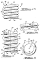
- a coil spring 40 as shown in Figures 1 and 2, is illustrated in detail in Figures 7, 8, 9 and 10.
- the spring 40 is made from wire 11 of diameter (d) with a plurality of active coils 50 each having a pitch P which is greater than the diameter (d) of the wire.
- each of the active coils has a deflection per coil, i.e., a gap between active coils which is labeled F.
- the arcuate flat surface 42 which is formed by grinding away coil section 52 is shown in Figure 7.
- the surface 42 is substantially perpendicular to the longitudinal axis 55 of spring 40.
- the end coil 44 and the flat surface 42 terminate at distal tip 46.
- the end coil 44 measured from the point 62 at which the pitch first substantially equals the diameter (d) of the wire, to the distal tip 46, extends for less than 360°.
- the ground flattened surface 42, from point 54 to distal tip 46 likewise extends for less than 360°, and extends fully within the end coil section which has pitch (d).
- the arcuate flattened end coil 44 is less than one coil turn.
- the flattened end coil section 44 spans between 170° and 300°. Desirably, the flattened end coil can be between 190° and 270°. In one application, the arcuate span is approximately 247°. It follows that the tip thickness is preferably at least 25% of the wire diameter.
- the surface 42 is substantially perpendicular to central axis 55.
- the tip thickness is related to the arc of the flattened surface.
- the tip thickness substantially equals
- the term can be referred to as a fraction (f).
- the phrase "arcuate flattened surface °" can also be referred to as the grind in degrees. If the transition coil section 70 has an average pitch significantly different than the active coil, the gap is measured
- the gap 66 between the tip 46 and point 64 depends on the pitch of transition section 70 from the starting point 54 of the flattened arcuate section to point 64 adjacent the tip 46.
- the gap measures: (1-f) x deflection of the active coils (F)
- the two tips 46 at the bottom and the top end coils are axially positioned such that they do not complete a full coil turn, i.e., they do not overlap in the axial direction.
- the total number of coils, i.e., the number of active coils, end coils and transition coil sections add up to slightly less than an entire turn, i.e., preferably less than an entire turn by an amount less than 1/4. In one embodiment, the amount should be approximately 1/10 less than an entire turn.
- the minimum acceptable gap and minimum acceptable tip thickness When manufacturing tolerances are taken into account to determine the minimum acceptable gap and minimum acceptable tip thickness, the maximum allowable arcuate flattened surface, the minimum allowable deflection per coil (F) and the minimum allowable wire diameter (d) should be used in the above calculations.
- each spring 40 is coiled on a conventional spring coiling machine with the wire being cut off and bent short of contacting the next adjacent coil. On removal from the coiling machine, the spring is stressed relieved, the ends are ground off, to provide a bearing surface and the ends are chamfered as shown in Figures 7-10 at section 43. The springs for some applications are shot peened to improve durability.
- the torsional vibration damper may seat two springs in parallel with each other in each cage 32.
- the springs may be coaxially mounted with one nested inside another.
- Each spring has end coil sections as above described.
- spring 40a and 40b have end coil sections constructed in the same fashion as spring 40 described above.
- Three springs 40a forming a spring set are connected in series between the seat 82 fixed to the input member 82 by rivets 83 and seat 93 of reactive members 86 and 87.
- Three springs 40b nested in springs 40a are also connected in series in the same fashion.
- Reactive members 86 and 87 are assembled by rivets 85 to an output hub 91.
- a spring retaining shell 95 is fixed to reactive member 87.
- a pair of floating spring seats 98 are slidably movable in the spring cage 100 defined between input member 80 and shell 95.
- the seats 98 can have bearings 97 rolling against shell 95.
- the floating seats 98 are interposed between two end coil sections of two adjacent springs 40a and two adjacent springs 40b.
- Identical sets of springs 40a and 40b are positioned between seats 93 and 82 on the left side of torsional vibration damper. For simplicity of the drawing, these springs are not shown in Figure 11.
- torsional vibration damper 80 has a combination of springs both in series and in parallel.
Landscapes
- Engineering & Computer Science (AREA)
- General Engineering & Computer Science (AREA)
- Mechanical Engineering (AREA)
- Physics & Mathematics (AREA)
- Acoustics & Sound (AREA)
- Aviation & Aerospace Engineering (AREA)
- Springs (AREA)
- Mechanical Operated Clutches (AREA)
Applications Claiming Priority (2)
| Application Number | Priority Date | Filing Date | Title |
|---|---|---|---|
| US728181 | 1985-04-29 | ||
| US72818191A | 1991-07-10 | 1991-07-10 |
Publications (3)
| Publication Number | Publication Date |
|---|---|
| EP0522718A2 true EP0522718A2 (fr) | 1993-01-13 |
| EP0522718A3 EP0522718A3 (fr) | 1993-01-20 |
| EP0522718B1 EP0522718B1 (fr) | 1996-01-24 |
Family
ID=24925747
Family Applications (1)
| Application Number | Title | Priority Date | Filing Date |
|---|---|---|---|
| EP19920305485 Expired - Lifetime EP0522718B1 (fr) | 1991-07-10 | 1992-06-15 | Amortisseur de vibrations torsionnelles |
Country Status (3)
| Country | Link |
|---|---|
| EP (1) | EP0522718B1 (fr) |
| JP (1) | JP3576179B2 (fr) |
| DE (1) | DE69207826T2 (fr) |
Cited By (4)
| Publication number | Priority date | Publication date | Assignee | Title |
|---|---|---|---|---|
| FR2894006A1 (fr) * | 2005-11-30 | 2007-06-01 | Valeo Embrayages | Double volant amortisseur |
| FR2894005A1 (fr) * | 2005-11-30 | 2007-06-01 | Valeo Embrayages | Double volant amortisseur |
| FR3013089A1 (fr) * | 2013-11-12 | 2015-05-15 | Valeo Embrayages | Support pour dispositif d'amortissement pour systeme de transmission de vehicule |
| CN107713730A (zh) * | 2017-10-31 | 2018-02-23 | 珠海格力电器股份有限公司 | 一种螺旋弹簧及一种烹饪厨具 |
Families Citing this family (5)
| Publication number | Priority date | Publication date | Assignee | Title |
|---|---|---|---|---|
| JP5003386B2 (ja) * | 2007-09-28 | 2012-08-15 | アイシン・エィ・ダブリュ株式会社 | コイルスプリング |
| JP2010071371A (ja) * | 2008-09-17 | 2010-04-02 | Showa Corp | 油圧緩衝器の減衰バルブ構造 |
| DE102014224436A1 (de) | 2014-11-28 | 2016-06-02 | Zf Friedrichshafen Ag | Federpaket |
| JP6998648B2 (ja) * | 2016-03-25 | 2022-01-18 | 株式会社エクセディ | スプリング組立体及びそれを備えたトルクコンバータのロックアップ装置 |
| JP7121131B2 (ja) * | 2018-09-06 | 2022-08-17 | 日本発條株式会社 | アークスプリングの成形方法及び成形装置 |
Family Cites Families (6)
| Publication number | Priority date | Publication date | Assignee | Title |
|---|---|---|---|---|
| US2026007A (en) * | 1934-01-04 | 1935-12-31 | Eaton Mfg Co | Coil spring |
| US2695169A (en) * | 1949-11-30 | 1954-11-23 | American Steel Foundries | Coil spring |
| FR1507552A (fr) * | 1966-01-27 | 1967-12-29 | Amsted Ind Inc | Ressort à boudin travaillant en compression |
| US4148469A (en) * | 1978-01-23 | 1979-04-10 | Standard Car Truck Company | Dual rate spring with elastic spring coupling |
| FR2495256A1 (fr) * | 1980-12-03 | 1982-06-04 | Valeo | Dispositif amortisseur de torsion, en particulier friction d'embrayage, notamment pour vehicule automobile |
| DE8530850U1 (de) * | 1985-10-31 | 1985-12-12 | SKF GmbH, 8720 Schweinfurt | Schraubenfeder |
-
1992
- 1992-06-15 EP EP19920305485 patent/EP0522718B1/fr not_active Expired - Lifetime
- 1992-06-15 DE DE1992607826 patent/DE69207826T2/de not_active Expired - Fee Related
- 1992-07-10 JP JP18375792A patent/JP3576179B2/ja not_active Expired - Lifetime
Cited By (10)
| Publication number | Priority date | Publication date | Assignee | Title |
|---|---|---|---|---|
| FR2894006A1 (fr) * | 2005-11-30 | 2007-06-01 | Valeo Embrayages | Double volant amortisseur |
| FR2894005A1 (fr) * | 2005-11-30 | 2007-06-01 | Valeo Embrayages | Double volant amortisseur |
| EP1793142A1 (fr) * | 2005-11-30 | 2007-06-06 | Valeo Embrayages | Double volant amortisseur |
| EP1793141A1 (fr) * | 2005-11-30 | 2007-06-06 | VALEO EMBRAYAGES s.a.s. | Amortisseur de torsion |
| FR3013089A1 (fr) * | 2013-11-12 | 2015-05-15 | Valeo Embrayages | Support pour dispositif d'amortissement pour systeme de transmission de vehicule |
| WO2015071577A1 (fr) * | 2013-11-12 | 2015-05-21 | Valeo Embrayages | Support pour dispositif d'amortissement pour système de transmission de véhicule |
| CN105899841A (zh) * | 2013-11-12 | 2016-08-24 | Valeo离合器公司 | 用于机动车传动系统的减振装置的支承件 |
| EP3069044B1 (fr) | 2013-11-12 | 2019-08-28 | Valeo Embrayages | Support pour dispositif d'amortissement pour système de transmission de véhicule |
| CN107713730A (zh) * | 2017-10-31 | 2018-02-23 | 珠海格力电器股份有限公司 | 一种螺旋弹簧及一种烹饪厨具 |
| CN107713730B (zh) * | 2017-10-31 | 2022-08-30 | 珠海格力电器股份有限公司 | 一种螺旋弹簧及一种烹饪厨具 |
Also Published As
| Publication number | Publication date |
|---|---|
| JPH05196075A (ja) | 1993-08-06 |
| EP0522718A3 (fr) | 1993-01-20 |
| DE69207826T2 (de) | 1996-05-30 |
| DE69207826D1 (de) | 1996-03-07 |
| EP0522718B1 (fr) | 1996-01-24 |
| JP3576179B2 (ja) | 2004-10-13 |
Similar Documents
| Publication | Publication Date | Title |
|---|---|---|
| US5464198A (en) | Torsional vibration damper having helical torsion springs | |
| US4810231A (en) | Torsional vibration damper having springs with progressive characteristics | |
| JP5473278B2 (ja) | トーショナルバイブレーションダンパ | |
| US8684342B2 (en) | Coil spring | |
| JP3618158B2 (ja) | トルクコンバータ用ロックアップクラッチのスプリングダンパー装置 | |
| EP0522718B1 (fr) | Amortisseur de vibrations torsionnelles | |
| GB2275983A (en) | Helical spring | |
| GB2069100A (en) | Damper disc | |
| EP1030072B1 (fr) | Disque d'embrayage | |
| WO1991006785A1 (fr) | Ressort arque et son procede de fabrication | |
| EP0096979A1 (fr) | Amortisseur de vibration à étages multiples | |
| US5259599A (en) | Coil spring, in particular for a torsion damper | |
| KR870000706B1 (ko) | 넓게 비틀어지는 각형 댐퍼 디스크(damper disc of a long travel type) | |
| US5937989A (en) | Clutch disk assembly having cushioning plates and paired friction pads riveted together | |
| US8876095B2 (en) | Coil spring | |
| US4269296A (en) | Two-stage coaxial spring damper | |
| EP0696694B1 (fr) | Disque absorbeur de couple de rotation | |
| KR20020025817A (ko) | 댐퍼 기구 | |
| US6375575B2 (en) | Damper mechanism | |
| US20020193165A1 (en) | Damper mechanism | |
| KR100470424B1 (ko) | 댐퍼 기구 | |
| EP1460302A1 (fr) | Amortisseur d'oscillations de torsion | |
| JPH0155691B2 (fr) | ||
| CN108679159B (zh) | 一种基于扭转减振带的无螺旋弹簧扭转减振器从动盘总成 | |
| EP1519065A2 (fr) | Ressort hélicoidal et transmission de couple et dispositif pour l'amortissement de variations de couple l'utilisant |
Legal Events
| Date | Code | Title | Description |
|---|---|---|---|
| PUAI | Public reference made under article 153(3) epc to a published international application that has entered the european phase |
Free format text: ORIGINAL CODE: 0009012 |
|
| PUAL | Search report despatched |
Free format text: ORIGINAL CODE: 0009013 |
|
| AK | Designated contracting states |
Kind code of ref document: A2 Designated state(s): DE FR GB |
|
| AK | Designated contracting states |
Kind code of ref document: A3 Designated state(s): DE FR GB |
|
| 17P | Request for examination filed |
Effective date: 19930507 |
|
| 17Q | First examination report despatched |
Effective date: 19940608 |
|
| GRAA | (expected) grant |
Free format text: ORIGINAL CODE: 0009210 |
|
| AK | Designated contracting states |
Kind code of ref document: B1 Designated state(s): DE FR GB |
|
| REF | Corresponds to: |
Ref document number: 69207826 Country of ref document: DE Date of ref document: 19960307 |
|
| ET | Fr: translation filed | ||
| PLBE | No opposition filed within time limit |
Free format text: ORIGINAL CODE: 0009261 |
|
| STAA | Information on the status of an ep patent application or granted ep patent |
Free format text: STATUS: NO OPPOSITION FILED WITHIN TIME LIMIT |
|
| 26N | No opposition filed | ||
| REG | Reference to a national code |
Ref country code: GB Ref legal event code: IF02 |
|
| PGFP | Annual fee paid to national office [announced via postgrant information from national office to epo] |
Ref country code: GB Payment date: 20030501 Year of fee payment: 12 |
|
| PGFP | Annual fee paid to national office [announced via postgrant information from national office to epo] |
Ref country code: FR Payment date: 20030602 Year of fee payment: 12 |
|
| PGFP | Annual fee paid to national office [announced via postgrant information from national office to epo] |
Ref country code: DE Payment date: 20030630 Year of fee payment: 12 |
|
| PG25 | Lapsed in a contracting state [announced via postgrant information from national office to epo] |
Ref country code: GB Free format text: LAPSE BECAUSE OF NON-PAYMENT OF DUE FEES Effective date: 20040615 |
|
| PG25 | Lapsed in a contracting state [announced via postgrant information from national office to epo] |
Ref country code: DE Free format text: LAPSE BECAUSE OF NON-PAYMENT OF DUE FEES Effective date: 20050101 |
|
| GBPC | Gb: european patent ceased through non-payment of renewal fee |
Effective date: 20040615 |
|
| PG25 | Lapsed in a contracting state [announced via postgrant information from national office to epo] |
Ref country code: FR Free format text: LAPSE BECAUSE OF NON-PAYMENT OF DUE FEES Effective date: 20050228 |
|
| REG | Reference to a national code |
Ref country code: FR Ref legal event code: ST |