EP1460302A1 - Amortisseur d'oscillations de torsion - Google Patents
Amortisseur d'oscillations de torsion Download PDFInfo
- Publication number
- EP1460302A1 EP1460302A1 EP04006120A EP04006120A EP1460302A1 EP 1460302 A1 EP1460302 A1 EP 1460302A1 EP 04006120 A EP04006120 A EP 04006120A EP 04006120 A EP04006120 A EP 04006120A EP 1460302 A1 EP1460302 A1 EP 1460302A1
- Authority
- EP
- European Patent Office
- Prior art keywords
- side plate
- rivet
- torsional damper
- damper apparatus
- clutch hub
- Prior art date
- Legal status (The legal status is an assumption and is not a legal conclusion. Google has not performed a legal analysis and makes no representation as to the accuracy of the status listed.)
- Granted
Links
- 230000000717 retained effect Effects 0.000 claims abstract description 11
- 238000000034 method Methods 0.000 description 6
- 230000005540 biological transmission Effects 0.000 description 1
- 238000013016 damping Methods 0.000 description 1
- 230000003247 decreasing effect Effects 0.000 description 1
- 230000002093 peripheral effect Effects 0.000 description 1
Images





Classifications
-
- F—MECHANICAL ENGINEERING; LIGHTING; HEATING; WEAPONS; BLASTING
- F16—ENGINEERING ELEMENTS AND UNITS; GENERAL MEASURES FOR PRODUCING AND MAINTAINING EFFECTIVE FUNCTIONING OF MACHINES OR INSTALLATIONS; THERMAL INSULATION IN GENERAL
- F16F—SPRINGS; SHOCK-ABSORBERS; MEANS FOR DAMPING VIBRATION
- F16F15/00—Suppression of vibrations in systems; Means or arrangements for avoiding or reducing out-of-balance forces, e.g. due to motion
- F16F15/10—Suppression of vibrations in rotating systems by making use of members moving with the system
- F16F15/12—Suppression of vibrations in rotating systems by making use of members moving with the system using elastic members or friction-damping members, e.g. between a rotating shaft and a gyratory mass mounted thereon
- F16F15/121—Suppression of vibrations in rotating systems by making use of members moving with the system using elastic members or friction-damping members, e.g. between a rotating shaft and a gyratory mass mounted thereon using springs as elastic members, e.g. metallic springs
- F16F15/123—Wound springs
- F16F15/1232—Wound springs characterised by the spring mounting
- F16F15/12326—End-caps for springs
- F16F15/12333—End-caps for springs having internal abutment means
-
- F—MECHANICAL ENGINEERING; LIGHTING; HEATING; WEAPONS; BLASTING
- F16—ENGINEERING ELEMENTS AND UNITS; GENERAL MEASURES FOR PRODUCING AND MAINTAINING EFFECTIVE FUNCTIONING OF MACHINES OR INSTALLATIONS; THERMAL INSULATION IN GENERAL
- F16F—SPRINGS; SHOCK-ABSORBERS; MEANS FOR DAMPING VIBRATION
- F16F15/00—Suppression of vibrations in systems; Means or arrangements for avoiding or reducing out-of-balance forces, e.g. due to motion
- F16F15/10—Suppression of vibrations in rotating systems by making use of members moving with the system
- F16F15/12—Suppression of vibrations in rotating systems by making use of members moving with the system using elastic members or friction-damping members, e.g. between a rotating shaft and a gyratory mass mounted thereon
- F16F15/1203—Suppression of vibrations in rotating systems by making use of members moving with the system using elastic members or friction-damping members, e.g. between a rotating shaft and a gyratory mass mounted thereon characterised by manufacturing, e.g. assembling or testing procedures for the damper units
-
- F—MECHANICAL ENGINEERING; LIGHTING; HEATING; WEAPONS; BLASTING
- F16—ENGINEERING ELEMENTS AND UNITS; GENERAL MEASURES FOR PRODUCING AND MAINTAINING EFFECTIVE FUNCTIONING OF MACHINES OR INSTALLATIONS; THERMAL INSULATION IN GENERAL
- F16F—SPRINGS; SHOCK-ABSORBERS; MEANS FOR DAMPING VIBRATION
- F16F15/00—Suppression of vibrations in systems; Means or arrangements for avoiding or reducing out-of-balance forces, e.g. due to motion
- F16F15/10—Suppression of vibrations in rotating systems by making use of members moving with the system
- F16F15/12—Suppression of vibrations in rotating systems by making use of members moving with the system using elastic members or friction-damping members, e.g. between a rotating shaft and a gyratory mass mounted thereon
- F16F15/129—Suppression of vibrations in rotating systems by making use of members moving with the system using elastic members or friction-damping members, e.g. between a rotating shaft and a gyratory mass mounted thereon characterised by friction-damping means
- F16F15/1295—Suppression of vibrations in rotating systems by making use of members moving with the system using elastic members or friction-damping members, e.g. between a rotating shaft and a gyratory mass mounted thereon characterised by friction-damping means characterised by means for interconnecting driven plates and retainer, cover plates
-
- F—MECHANICAL ENGINEERING; LIGHTING; HEATING; WEAPONS; BLASTING
- F16—ENGINEERING ELEMENTS AND UNITS; GENERAL MEASURES FOR PRODUCING AND MAINTAINING EFFECTIVE FUNCTIONING OF MACHINES OR INSTALLATIONS; THERMAL INSULATION IN GENERAL
- F16B—DEVICES FOR FASTENING OR SECURING CONSTRUCTIONAL ELEMENTS OR MACHINE PARTS TOGETHER, e.g. NAILS, BOLTS, CIRCLIPS, CLAMPS, CLIPS OR WEDGES; JOINTS OR JOINTING
- F16B19/00—Bolts without screw-thread; Pins, including deformable elements; Rivets
- F16B19/04—Rivets; Spigots or the like fastened by riveting
- F16B19/06—Solid rivets made in one piece
-
- F—MECHANICAL ENGINEERING; LIGHTING; HEATING; WEAPONS; BLASTING
- F16—ENGINEERING ELEMENTS AND UNITS; GENERAL MEASURES FOR PRODUCING AND MAINTAINING EFFECTIVE FUNCTIONING OF MACHINES OR INSTALLATIONS; THERMAL INSULATION IN GENERAL
- F16B—DEVICES FOR FASTENING OR SECURING CONSTRUCTIONAL ELEMENTS OR MACHINE PARTS TOGETHER, e.g. NAILS, BOLTS, CIRCLIPS, CLAMPS, CLIPS OR WEDGES; JOINTS OR JOINTING
- F16B5/00—Joining sheets or plates, e.g. panels, to one another or to strips or bars parallel to them
- F16B5/04—Joining sheets or plates, e.g. panels, to one another or to strips or bars parallel to them by means of riveting
Definitions
- the present invention generally relates to a torsional damper apparatus used for a clutch disk for vehicle and the like. More particularly, the present invention pertains to a torsional damper apparatus which can be assembled with a less process.
- a clutch disk is generally equipped with a damper device in a rotating direction.
- a damper device is disclosed in Japanese Patent Laid-Open Publication No. H11(1999)-18257s.
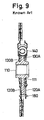
- a damper device 101 includes a clutch hub 110 and side plates 120A and 120B between which a damper element such as a coil spring 140, thrust members 130A and 130B is disposed.
- the damper element is held between a pair of side plates 120A and 120B.
- the pair of side plates 120A and 120B are connected to each other via rivet pins 180.
- each rivet pin 180 having a flat shape includes a body portion 181 arranged between the pair of side plates 120A and 120B, rivet portions 182 and 183 for riveting the side plates 120A and 120B each other.
- a great number of rivet pins 180 are used for connecting the side plates 120A and 120B to each other to thereby assure the strength.
- the rivet pins 180 are provided at an outer circumferential side of the side plates 120A and 120B in order to improve the torsional damping performance of the clutch disk.
- the assembly process is increased and then the cost is increased.
- the number of the rivet pins 180 cannot be decreased for achieving the strength.
- the rivet pin 180 which of flat shape is unstable and easy to fall down when being inserted into a hole formed on the side plate as compared to a rivet pin which of round shape, thereby requiring a wasting time for assembly.
- a torsional damper apparatus includes a clutch hub having a hub portion and a flange portion extending in a radially outward direction from the hub portion, a first side plate and a second side plate disposed on opposite sides of the clutch hub in an axial direction, a first thrust member retained between the first side plate and the clutch hub, and a second thrust member retained between the second side plate and the clutch hub.
- the torsional damper apparatus further includes an annular cushion spring whose radially inner portion is connected to a radially outer portion of the second side plate, and a plurality of rivet pins for connecting the first side plate and the second side plate by riveting. At least two rivet pins arranged next to each other are integrally formed.
- a torsional damper apparatus includes a clutch hub having a hub portion and a flange portion extending in a radially outward direction from the hub portion, a first side plate and a second side plate disposed on opposite sides of the clutch hub in an axial direction, a first thrust member retained between the first side plate and the clutch hub, and a second thrust member retained between the second side plate and the clutch hub.
- the torsional damper apparatus further includes an annular cushion spring whose radially inner portion is connected to a radially outer portion of the second side plate, and a plurality of rivet pins for connecting the first side plate and the second side plate by riveting.
- the rivet pins each include a body portion provided between the first side plate and the second side plate, a plurality of flat-type first rivet portions formed at one end of the body portion, and a plurality of flat-type second rivet portions formed at the other end of the body portion.
- the first rivet portions are each riveted by being inserted into each first through-hole formed on the first side plate and the second rivet portions are each riveted by being inserted into each second through-hole formed on the second side plate.
- the assembly process may be widely reduced without losing the strength of riveting. Further, no extra assembly process is required by using the flat-type rivet pins.
- Fig. 1 is a front view showing a structure of a torsional damper apparatus 1 according to the first embodiment.
- Fig. 2 is a cross-sectional view taken along a line A-A' of Fig. 1.
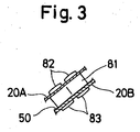
- Fig. 3 is a partial cross-sectional view taken along a line B-B' of Fig. 1.
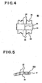
- Fig. 4 is a front view showing a structure of a rivet pin of the torsional damper apparatus 1.
- Fig. 5 is a top view of the rivet pin.
- the torsional damper apparatus 1 is employed in a clutch disk and includes a clutch hub 10, a side plate 20, a thrust member 30, a coil spring 40, a cushion spring 50, a friction element 60, a rivet 70 and a rivet pin 80.
- the clutch hub 10 includes a hub portion and a flange 11 extending in a radially outward direction from the hub portion as shown in Figs. 1 and 2.
- the flange 11 is formed as a unit with the hub portion of the clutch hub 10.
- the flange 11 and the hub portion may be separately formed so that a small spring can be disposed therebetween. Then, a small torsional vibration can be absorbed between the flange 11 and the hub portion.
- the clutch hub 10 also includes a notch 12 that opens in the radially outward direction of the flange 11.
- the notch 12 is constituted in such a manner that an outer circumferential side of a spring seat 41 (See Fig. 1) is positioned radially outward relative to an outer circumferential side of the flange 11.
- the side plate 20 is coaxially provided and relatively rotatable with the clutch hub 10. As shown in Fig. 2, the side plate 20 includes a first side plate 20A and a second side plate 20B disposed on opposite sides of the clutch hub 10 in an axial direction.
- the first side plate 20A and the second side plate 20B include window holes 21 for connecting the outer circumferential side of the coil spring 40.
- through-holes 22A and 22B are formed on the first side plate 20A and the second side plate 20B respectively so as to be used for connecting the first side plate 20A and the second side plate 20B to each other at each circumferential portion thereof via the rivet pins 80.
- the washer-type thrust member 30 is disposed between respective contact faces of the clutch hub 10 and the side plate 20. As shown in Fig. 2, the thrust member 30 includes a first thrust member 30A disposed between the respective contact faces of the clutch hub 10 and the first side plate 20A and a second thrust member 30B disposed between the respective contact faces of the clutch hub 10 and the second side plate 20B.
- the coil spring 40 is disposed in the notch 12 and the window holes 21, facing to each other, formed on the clutch hub 10 and the side plates 20A and 20B respectively.
- Four coil springs 40 (or possibly two) are employed according to the present embodiment as shown in Fig. 1.
- Each coil spring 40 is received within the notch 12 and the window hole 21 while being supported by a pair of spring seats 41 and 42.
- a radially inward portion of the cushion spring 50 is connected to a radially outward portion of the second side plate 20B as shown in Fig. 2.
- the cushion spring 50 and the second side plate 20B are connected to each . other via the rivet pins 80.
- the cushion spring 50 includes a through-hole 51 for facing to a body portion 81 of the rivet pin 80 in a region corresponding to, i.e. overlapping, the through-hole 22B formed on the second side plate 20B so that the rivet pin 80 is stably positioned.
- a pair of friction elements 60 each having an annular shape are fixed to opposite sides of the cushion spring 50 in the axial direction via the rivets 70.
- the rivet pin 80 connects the first side plate 20A and the second side plate 20B and includes the body portion 81 placed between the first side plate 20A and the second side plate 20B, a plurality of flat-type first rivet portions 82 at one end of the body portion 81, and a plurality of flat-type second rivet portions 83, whose number is equal to that of the first rivet portions 82, at the other end of the body portion 81.
- the body portion 81 includes a bent portion 84 on a side wall face positioned corresponding to the through-hole 22A formed on the first side plate 20A and the through-hole 22B formed on the second side plate 20B.
- the body portion 81 may include a curved face portion on the side wall face positioned corresponding to the through-holes 22A and 22B.
- the first rivet portion 82 is riveted being inserted into the through-hole 22A of the first side plate 20A while the second rivet portion 83 is riveted being inserted into the through-hole 22B of the second side plate 20B. Corners of side walls of the first rivet portion 82 and the second rivet portion 83 are each in a round shape (such as a round corner 82A in Fig. 2B) so that the stress applied to the through-hole 22A of the first side plate 20A and the through-hole 22B of the second side plate 20B can be reduced.
- the first rivet portion 82 and the second rivet portion 83 each include a V-shaped or U-shaped concave portion 85 in a region including a center portion of one end face provided perpendicular to a flat face of the side wall of each first rivet portion 82 or the second rivet portion 83, i.e. the one end face provided opposite to the other end face of the first rivet portion 82 or the second rivet portion 83 fitted to the body portion 81, so that the stress after riveting can be reduced.
- the rivet pin 80 is desirably formed by being stamped out with a press for achieving the reduced cost.
- a cross-section of the body portion 81 perpendicular to the side wall face thereof and in a direction in which the first rivet portion 82 is extending has a substantially rectangular shape.
- the pair of friction elements 60 are retained between an engine flywheel and a pressure plate (not shown).
- the clutch hub 10 is provided with a spline portion at an inner peripheral surface where an input shaft of a transmission (not shown) having a spline portion is engaged.
- the torsional damper apparatus 1 according to the present embodiment is employed in the clutch disk in an aforementioned manner.
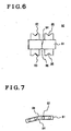
- Fig. 6 is a front view showing the structure of the rivet pin 8.
- Fig. 7 is a top view of the rivet pin 8.
- the body portion 81 of the rivet pin 80 includes a notch portion 86 in a region including a portion in which one end face of the body portion 81 on the first rivet portion 82 side and the other end face of the body portion 81 on the second rivet portion 83 side each cross the bent portion 84. Then, each part may be smoothly assembled when riveted. Further, creases formed at an inner side of the bent portion 84 when the flat rivet pin 80 is bent may prevent a portion of the end faces of the body portion 81 from being raised.
Landscapes
- Engineering & Computer Science (AREA)
- General Engineering & Computer Science (AREA)
- Physics & Mathematics (AREA)
- Acoustics & Sound (AREA)
- Aviation & Aerospace Engineering (AREA)
- Mechanical Engineering (AREA)
- Mechanical Operated Clutches (AREA)
Applications Claiming Priority (2)
| Application Number | Priority Date | Filing Date | Title |
|---|---|---|---|
| JP2003073207 | 2003-03-18 | ||
| JP2003073207A JP4239627B2 (ja) | 2003-03-18 | 2003-03-18 | 捩れ緩衝装置 |
Publications (2)
| Publication Number | Publication Date |
|---|---|
| EP1460302A1 true EP1460302A1 (fr) | 2004-09-22 |
| EP1460302B1 EP1460302B1 (fr) | 2007-08-01 |
Family
ID=32821304
Family Applications (1)
| Application Number | Title | Priority Date | Filing Date |
|---|---|---|---|
| EP20040006120 Expired - Lifetime EP1460302B1 (fr) | 2003-03-18 | 2004-03-15 | Amortisseur d'oscillations de torsion |
Country Status (4)
| Country | Link |
|---|---|
| EP (1) | EP1460302B1 (fr) |
| JP (1) | JP4239627B2 (fr) |
| CN (1) | CN1293321C (fr) |
| DE (1) | DE602004007841T2 (fr) |
Cited By (1)
| Publication number | Priority date | Publication date | Assignee | Title |
|---|---|---|---|---|
| WO2007124709A1 (fr) * | 2006-04-28 | 2007-11-08 | Luk Lamellen Und Kupplungsbau Beteiligungs Kg | Dispositif de disque a embrayage |
Families Citing this family (8)
| Publication number | Priority date | Publication date | Assignee | Title |
|---|---|---|---|---|
| EP1936232A3 (fr) * | 2006-12-18 | 2009-07-08 | LuK Lamellen und Kupplungsbau Beteiligungs KG | Amortisseur de vibrations de torsions |
| JP5772098B2 (ja) * | 2011-03-15 | 2015-09-02 | アイシン精機株式会社 | トルク変動吸収装置 |
| CN103527655A (zh) * | 2013-10-23 | 2014-01-22 | 中国重汽集团济南动力有限公司 | 一种带有扭转减振及限位功能的车用离合器从动盘 |
| FR3051868B1 (fr) * | 2016-05-30 | 2019-01-25 | Valeo Embrayages | Dispositif d'amortissement pour embrayage de vehicule automobile et embrayage comprenant un tel dispositif |
| JP2018141503A (ja) | 2017-02-27 | 2018-09-13 | アイシン精機株式会社 | ダンパ装置 |
| JP2018141504A (ja) * | 2017-02-27 | 2018-09-13 | アイシン精機株式会社 | ダンパ装置 |
| JP2019158048A (ja) * | 2018-03-14 | 2019-09-19 | 株式会社エクセディ | かしめ加工用ピン及び動力伝達構造 |
| CN112360923B (zh) * | 2020-10-15 | 2021-07-13 | 东风汽车集团有限公司 | 一种减震盘总成及两级阻尼限扭减震器 |
Citations (4)
| Publication number | Priority date | Publication date | Assignee | Title |
|---|---|---|---|---|
| DE2209493A1 (de) * | 1972-02-29 | 1973-09-13 | Walther Dipl Ing Zarges | Nietverbindung |
| EP0437125A2 (fr) * | 1989-12-12 | 1991-07-17 | Valeo | Dispositif amortisseur de torsion, notamment pour embrayages de véhicules automobiles |
| US5839182A (en) * | 1994-08-24 | 1998-11-24 | Exedy Corporation | Manufacturing method for clutch disc subassembly |
| JPH11182576A (ja) * | 1997-12-22 | 1999-07-06 | Exedy Corp | ストップピン及びダンパーディスク組立体 |
Family Cites Families (6)
| Publication number | Priority date | Publication date | Assignee | Title |
|---|---|---|---|---|
| JPS474369U (fr) * | 1971-02-08 | 1972-09-09 | ||
| JPS5941060U (ja) * | 1982-09-10 | 1984-03-16 | アルプス電気株式会社 | モ−タ−用成形リベツト |
| DE3918222A1 (de) * | 1988-06-04 | 1989-12-07 | Luk Lamellen & Kupplungsbau | Daempfungsvorkehrung |
| JP4034882B2 (ja) * | 1998-06-25 | 2008-01-16 | ヴァレオユニシアトランスミッション株式会社 | クラッチディスク |
| JP2001146913A (ja) * | 1999-11-24 | 2001-05-29 | Toyota Motor Corp | リベット及びリベットによる結合方法 |
| JP2002130324A (ja) * | 2000-10-31 | 2002-05-09 | Exedy Corp | クラッチ用クッショニングプレートの製造方法 |
-
2003
- 2003-03-18 JP JP2003073207A patent/JP4239627B2/ja not_active Expired - Fee Related
-
2004
- 2004-03-15 DE DE200460007841 patent/DE602004007841T2/de not_active Expired - Lifetime
- 2004-03-15 EP EP20040006120 patent/EP1460302B1/fr not_active Expired - Lifetime
- 2004-03-18 CN CNB2004100300464A patent/CN1293321C/zh not_active Expired - Fee Related
Patent Citations (4)
| Publication number | Priority date | Publication date | Assignee | Title |
|---|---|---|---|---|
| DE2209493A1 (de) * | 1972-02-29 | 1973-09-13 | Walther Dipl Ing Zarges | Nietverbindung |
| EP0437125A2 (fr) * | 1989-12-12 | 1991-07-17 | Valeo | Dispositif amortisseur de torsion, notamment pour embrayages de véhicules automobiles |
| US5839182A (en) * | 1994-08-24 | 1998-11-24 | Exedy Corporation | Manufacturing method for clutch disc subassembly |
| JPH11182576A (ja) * | 1997-12-22 | 1999-07-06 | Exedy Corp | ストップピン及びダンパーディスク組立体 |
Non-Patent Citations (1)
| Title |
|---|
| PATENT ABSTRACTS OF JAPAN vol. 1999, no. 12 29 October 1999 (1999-10-29) * |
Cited By (1)
| Publication number | Priority date | Publication date | Assignee | Title |
|---|---|---|---|---|
| WO2007124709A1 (fr) * | 2006-04-28 | 2007-11-08 | Luk Lamellen Und Kupplungsbau Beteiligungs Kg | Dispositif de disque a embrayage |
Also Published As
| Publication number | Publication date |
|---|---|
| JP4239627B2 (ja) | 2009-03-18 |
| DE602004007841T2 (de) | 2008-04-17 |
| JP2004278727A (ja) | 2004-10-07 |
| CN1532433A (zh) | 2004-09-29 |
| DE602004007841D1 (de) | 2007-09-13 |
| EP1460302B1 (fr) | 2007-08-01 |
| CN1293321C (zh) | 2007-01-03 |
Similar Documents
| Publication | Publication Date | Title |
|---|---|---|
| US4485909A (en) | Multiple stage vibration damper | |
| JPH0147651B2 (fr) | ||
| GB2085552A (en) | Damper Disc | |
| JPH0645724Y2 (ja) | ダンパーディスク | |
| EP1460302A1 (fr) | Amortisseur d'oscillations de torsion | |
| EP0784164B2 (fr) | Ensemble de disque amortisseur avec une connection pour un disque intégral de retenue | |
| US6375575B2 (en) | Damper mechanism | |
| US4690660A (en) | Damper disc | |
| JP3434391B2 (ja) | ダンパーディスク組立体 | |
| EP1348886A1 (fr) | Disque amortisseur de torsion | |
| US5401213A (en) | Clutch and damper assembly | |
| EP0790433A2 (fr) | Elément de plaque pour un ensemble de disque amortisseur comportant des pièces de support s'étendant radialement | |
| JPH0624603Y2 (ja) | トルクコンバ−タのロツクアツプダンパ− | |
| CN113557370A (zh) | 离合器从动盘及离合器 | |
| KR920008169B1 (ko) | 댐퍼 디스크의 스프링 지지체 | |
| JP2001304378A (ja) | ダンパー構造及びその構造のダンパーを有するトルクコンバータ用ロックアップクラッチ | |
| US6482093B1 (en) | Damper disk assembly | |
| KR20120039307A (ko) | 차량용 토크 컨버터 | |
| JP3593435B2 (ja) | トルクコンバータのロックアップダンパー | |
| JPH0227238Y2 (fr) | ||
| GB2292784A (en) | Torsional vibration damper | |
| US6978695B2 (en) | Flywheel assembly | |
| CN222277298U (zh) | 扭矩限制器、传动组件和车辆 | |
| JPH11101268A (ja) | クラッチディスク組立体 | |
| JPH11241731A (ja) | ダンパー機構 |
Legal Events
| Date | Code | Title | Description |
|---|---|---|---|
| PUAI | Public reference made under article 153(3) epc to a published international application that has entered the european phase |
Free format text: ORIGINAL CODE: 0009012 |
|
| AK | Designated contracting states |
Kind code of ref document: A1 Designated state(s): AT BE BG CH CY CZ DE DK EE ES FI FR GB GR HU IE IT LI LU MC NL PL PT RO SE SI SK TR |
|
| AX | Request for extension of the european patent |
Extension state: AL LT LV MK |
|
| 17P | Request for examination filed |
Effective date: 20041001 |
|
| AKX | Designation fees paid |
Designated state(s): DE FR GB |
|
| 17Q | First examination report despatched |
Effective date: 20050502 |
|
| GRAP | Despatch of communication of intention to grant a patent |
Free format text: ORIGINAL CODE: EPIDOSNIGR1 |
|
| GRAS | Grant fee paid |
Free format text: ORIGINAL CODE: EPIDOSNIGR3 |
|
| GRAA | (expected) grant |
Free format text: ORIGINAL CODE: 0009210 |
|
| AK | Designated contracting states |
Kind code of ref document: B1 Designated state(s): DE FR GB |
|
| REG | Reference to a national code |
Ref country code: GB Ref legal event code: FG4D |
|
| RIN1 | Information on inventor provided before grant (corrected) |
Inventor name: FUKAYA, NOBUKI Inventor name: TAKASHI, YUKIHISA Inventor name: KITADA, KOJI |
|
| REF | Corresponds to: |
Ref document number: 602004007841 Country of ref document: DE Date of ref document: 20070913 Kind code of ref document: P |
|
| ET | Fr: translation filed | ||
| PLBE | No opposition filed within time limit |
Free format text: ORIGINAL CODE: 0009261 |
|
| STAA | Information on the status of an ep patent application or granted ep patent |
Free format text: STATUS: NO OPPOSITION FILED WITHIN TIME LIMIT |
|
| 26N | No opposition filed |
Effective date: 20080506 |
|
| GBPC | Gb: european patent ceased through non-payment of renewal fee |
Effective date: 20080315 |
|
| PG25 | Lapsed in a contracting state [announced via postgrant information from national office to epo] |
Ref country code: GB Free format text: LAPSE BECAUSE OF NON-PAYMENT OF DUE FEES Effective date: 20080315 |
|
| REG | Reference to a national code |
Ref country code: FR Ref legal event code: PLFP Year of fee payment: 13 |
|
| REG | Reference to a national code |
Ref country code: FR Ref legal event code: PLFP Year of fee payment: 14 |
|
| REG | Reference to a national code |
Ref country code: FR Ref legal event code: PLFP Year of fee payment: 15 |
|
| PGFP | Annual fee paid to national office [announced via postgrant information from national office to epo] |
Ref country code: DE Payment date: 20220203 Year of fee payment: 19 |
|
| PGFP | Annual fee paid to national office [announced via postgrant information from national office to epo] |
Ref country code: FR Payment date: 20220210 Year of fee payment: 19 |
|
| REG | Reference to a national code |
Ref country code: DE Ref legal event code: R119 Ref document number: 602004007841 Country of ref document: DE |
|
| PG25 | Lapsed in a contracting state [announced via postgrant information from national office to epo] |
Ref country code: FR Free format text: LAPSE BECAUSE OF NON-PAYMENT OF DUE FEES Effective date: 20230331 Ref country code: DE Free format text: LAPSE BECAUSE OF NON-PAYMENT OF DUE FEES Effective date: 20231003 |