EP0523462A2 - Méthode pour enlever des revêtements externes des tubes - Google Patents
Méthode pour enlever des revêtements externes des tubes Download PDFInfo
- Publication number
- EP0523462A2 EP0523462A2 EP92111241A EP92111241A EP0523462A2 EP 0523462 A2 EP0523462 A2 EP 0523462A2 EP 92111241 A EP92111241 A EP 92111241A EP 92111241 A EP92111241 A EP 92111241A EP 0523462 A2 EP0523462 A2 EP 0523462A2
- Authority
- EP
- European Patent Office
- Prior art keywords
- coating
- nozzle
- pipe
- tube
- pipes
- Prior art date
- Legal status (The legal status is an assumption and is not a legal conclusion. Google has not performed a legal analysis and makes no representation as to the accuracy of the status listed.)
- Withdrawn
Links
Images
Classifications
-
- B—PERFORMING OPERATIONS; TRANSPORTING
- B24—GRINDING; POLISHING
- B24C—ABRASIVE OR RELATED BLASTING WITH PARTICULATE MATERIAL
- B24C1/00—Methods for use of abrasive blasting for producing particular effects; Use of auxiliary equipment in connection with such methods
- B24C1/08—Methods for use of abrasive blasting for producing particular effects; Use of auxiliary equipment in connection with such methods for polishing surfaces, e.g. smoothing a surface by making use of liquid-borne abrasives
- B24C1/086—Descaling; Removing coating films
-
- B—PERFORMING OPERATIONS; TRANSPORTING
- B24—GRINDING; POLISHING
- B24C—ABRASIVE OR RELATED BLASTING WITH PARTICULATE MATERIAL
- B24C3/00—Abrasive blasting machines or devices; Plants
- B24C3/08—Abrasive blasting machines or devices; Plants essentially adapted for abrasive blasting of travelling stock or travelling workpieces
- B24C3/10—Abrasive blasting machines or devices; Plants essentially adapted for abrasive blasting of travelling stock or travelling workpieces for treating external surfaces
- B24C3/12—Apparatus using nozzles
-
- B—PERFORMING OPERATIONS; TRANSPORTING
- B24—GRINDING; POLISHING
- B24C—ABRASIVE OR RELATED BLASTING WITH PARTICULATE MATERIAL
- B24C3/00—Abrasive blasting machines or devices; Plants
- B24C3/18—Abrasive blasting machines or devices; Plants essentially provided with means for moving workpieces into different working positions
-
- B—PERFORMING OPERATIONS; TRANSPORTING
- B24—GRINDING; POLISHING
- B24C—ABRASIVE OR RELATED BLASTING WITH PARTICULATE MATERIAL
- B24C3/00—Abrasive blasting machines or devices; Plants
- B24C3/32—Abrasive blasting machines or devices; Plants designed for abrasive blasting of particular work, e.g. the internal surfaces of cylinder blocks
-
- B—PERFORMING OPERATIONS; TRANSPORTING
- B26—HAND CUTTING TOOLS; CUTTING; SEVERING
- B26F—PERFORATING; PUNCHING; CUTTING-OUT; STAMPING-OUT; SEVERING BY MEANS OTHER THAN CUTTING
- B26F3/00—Severing by means other than cutting; Apparatus therefor
Definitions
- the invention relates to a method according to the preamble of the main claim.
- the removal of coatings on pipes or rods is a process that is often necessary in the manufacture or further processing of such products.
- the production of pipes coated with polyethylene up to an outside diameter of approx. 600 mm by a continuous hose extrusion process in which an endless strand produced by coupling individual pipes in a coating line initially e.g. sprayed with epoxy resin and / or adhesive and then passed through an extruder with an annular slot die.
- the pipe end and coupling areas - measured at approx. 300 mm from the pipe end - are kept free of glue and epoxy resin.
- the 200 ° C warm polyethylene emerges through this ring slot nozzle and is drawn onto the pipe by negative pressure.
- the entire strand, i.e. All couplings and joints are also covered with a polyethylene hose, which must be removed after cooling and hardening in the coupling and joint areas for pipe separation and for removing the coupling.
- the polyethylene coating is removed in the area of the opposite pipe ends over a length of approx. 300 mm. This cut back of the coating also prevents coating parts from burning due to the heat input which occurs during the later construction of the pipe during the welding of pipes.
- the coating in the tube end area is usually removed by two with a knife or by means of Cutting devices introduced circumferential cuts in the pipe end area, which are then connected with a longitudinal cut.
- the resulting slotted coating ring is then sheared off.
- a disadvantage of the first-mentioned manual knife cut is the fact that the pipe string is transported further during the cutting movement and that it becomes very difficult to achieve a circumferential and not helically distorted cut, especially with pipes with a large pipe outside diameter of, for example, 508 mm. In addition, this activity is rightly considered to be physically difficult and prone to accidents.
- both the knife cut and any cutting devices that are present show damage to the base coating or cutting through until the base material is removed.
- this therefore includes the "scratching" of the steel.
- this leads to the infiltration of the adjacent coating and thus to its loosening.
- the substrate - both the lower layers and the pipe material - can also be damaged here, since the high adhesion of the coating means that correspondingly strong mechanical abrasive agents must be used.
- the object of the invention was to provide a method with which coatings on pipes can be removed during the manufacture, processing and use of such products without damaging a substrate and thus causing further infiltration or other changes, which is safe and easy to use both during production and on the construction site, and its effect can also be adjusted and used for different coatings.
- the main idea of the invention is that one or more high-energy fluid jets emerging from nozzles arranged near the coating surface are directed onto the coating surface in such a way that a peeling effect arising from a component of motion of the fluid jet that builds up axially to the tube axis occurs as soon as the high-energy fluid jet or jets the coating cut through and hit the pipe material which is harder or less brittle relative to the coating material.
- At least one of the fluid jets has a tangentially oriented and / or a speed component aligned parallel to the pipe axis and at least its nozzle executes a relative movement to the coating, which has a tangential and a movement component directed parallel to the pipe axis.
- a screw-shaped peeling strip can be adjusted in width and length, which can be used for processing and removing a defective coating over the entire length Tube length is ashamed. Only a partial removal of the coating - for example in modern continuous coating systems - only in the area of the pipe ends can be easily achieved by gradually eliminating the movement component of the relative movement of the nozzle parallel to the pipe axis after a certain time and according to a certain pipe length. The fluid jet is then switched off until the next tube burst.
- a pure separation of the coating of a continuously coated pipe string in the joint area of the pipes or in the area of the coupling is also easily possible with this method in that no movement component of the relative movement of the nozzle parallel to the pipe axis is provided.
- a particularly simple and easy way of integrating the relative movement between the nozzle and the tube is that the tube is rotated and the nozzle or tube is fed axially parallel.
- the tube is then passed, for example, on an inclined roller table located in a container, with a helical movement, past a stationary nozzle located in the container.
- the container is of course provided with tubular openings on both ends.
- Kinematic reversals of this type of movement such as in the form of a nozzle rotating on a circular path around an axially moving tube, allow simple integration within existing coating systems.
- a further advantageous embodiment of the method consists in using at least one fluid jet as a separating or pre-cutting jet.
- this method enables the coating to be cut into a depth-adjustable manner and by a second fluid jet with an axial component in the separating agent, adhesive - or peeling off epoxy resin layer.
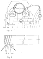
- a high-energy fluid jet 4 emerging from a nozzle 3 is directed onto the surface 5 in such a way that it has a tangentially oriented and a speed component aligned parallel to the pipe axis.
- the fluid jet 4 is generated by a high-pressure pump 6, which is connected to the nozzle 3 via conventional supply and discharge lines and valves 7, 8 and 9.
- a hood 10 protects the environment from bouncing jet water.
- the fluid jet device 11 is mounted on a carriage 12, which travels over the entire or only part of the tube length, the coating being peeled off.
- the nozzle 3 is completed by the second nozzle 13, which, according to FIG. 2, is used as a pure pre-cutting nozzle which also converts the coating, which is very elastic and therefore would convert a large amount of the velocity energy of the fluid jet 4 into deformation work cuts through the fluid jet 14 to the peeling depth. Thereafter, the axial or tangential component of the fluid jet 4 is sufficient for the peeling function when the fluid jet 4 can enter the cutting gap 15, as shown in FIG. 2.
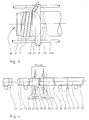
- Fig. 3 shows the application of the method for the end machining of a single tube.
- the pipe end 16 which is to be freed from the coating 18 for the subsequent welding along the length 17, rotates on a device, not shown, provided with carrier rollers.
- the nozzle 19 travels over the length 17 by means of its crossmember 21 held on guides 20, 20a and then stops in the feed movement. The rotation of the tube is then stopped and the nozzle 19 travels with the emerging fluid jet 22 back to the tube end, the helically peeled coating being broken up into individual rings and being easily removed from the tube end.
- Fig. 4 shows the pipes 25, 26 and 27 connected by means of couplings 23 to form a pipe string 24, which with a Endless polyethylene hose 28 are coated within an automatic insulation system.
- nozzles 30, 31, 32 and 33 arranged in two pairs are mounted on a carriage 29 which can be moved parallel to the tube axis, the nozzles 30 to 33 being able to be rotated in a ring around the tube.
- the carriage 29 travels at the pipe speed as soon as a pipe joint 35 provided with a coupling 23 is located within the nozzle rings. This is initiated by the detector 36, which also gives the output signal for the rotation of the nozzles 30 to 33, the emerging fluid jet of which cuts the polyethylene coating in a circular manner in the end regions.
- the nozzles 30 and 31 then cut the helically coated coating into half rings, which easily fall off the pipe as the production line continues. After the pipe string has been separated into individual pipes, the coupling 23 can be removed at a later production point 37.
Landscapes
- Engineering & Computer Science (AREA)
- Mechanical Engineering (AREA)
- Life Sciences & Earth Sciences (AREA)
- Forests & Forestry (AREA)
- Application Of Or Painting With Fluid Materials (AREA)
- Separation Using Semi-Permeable Membranes (AREA)
Applications Claiming Priority (2)
| Application Number | Priority Date | Filing Date | Title |
|---|---|---|---|
| DE4124084 | 1991-07-19 | ||
| DE4124084A DE4124084A1 (de) | 1991-07-19 | 1991-07-19 | Verfahren zum entfernen von auf rohren befindlichen beschichtungen |
Publications (2)
| Publication Number | Publication Date |
|---|---|
| EP0523462A2 true EP0523462A2 (fr) | 1993-01-20 |
| EP0523462A3 EP0523462A3 (en) | 1993-03-03 |
Family
ID=6436617
Family Applications (1)
| Application Number | Title | Priority Date | Filing Date |
|---|---|---|---|
| EP19920111241 Withdrawn EP0523462A3 (en) | 1991-07-19 | 1992-07-02 | Method to remove external coatings from pipelines |
Country Status (3)
| Country | Link |
|---|---|
| EP (1) | EP0523462A3 (fr) |
| DE (1) | DE4124084A1 (fr) |
| ES (1) | ES2036985T1 (fr) |
Cited By (6)
| Publication number | Priority date | Publication date | Assignee | Title |
|---|---|---|---|---|
| WO2000029142A1 (fr) * | 1998-11-16 | 2000-05-25 | Michel Cauche | Procede pour former des troncons de conduite courbes avec des tubes en acier munis d'un revetement de mortier |
| DE202011002773U1 (de) * | 2011-02-15 | 2012-05-16 | Tilo Klett | Wasserstrahlschneidmaschine zum Bearbeiten rohrförmiger Werkstücke |
| RU2522346C1 (ru) * | 2012-12-27 | 2014-07-10 | Открытое акционерное общество "Татнефть" имени В.Д. Шашина | Устройство для очистки наружной поверхности концевых участков труб от изоляции |
| CN104552020A (zh) * | 2015-02-02 | 2015-04-29 | 湖南湘能重工有限公司 | 风塔外壁抛丸清理机 |
| CN107187850A (zh) * | 2017-04-28 | 2017-09-22 | 重庆良能机械有限公司 | 管道输送装置 |
| CN112706082A (zh) * | 2020-12-30 | 2021-04-27 | 苏州贝利氟塑制品有限公司 | 表面除锈喷砂机 |
Families Citing this family (3)
| Publication number | Priority date | Publication date | Assignee | Title |
|---|---|---|---|---|
| DE4304551C1 (de) * | 1993-02-10 | 1994-02-24 | Mannesmann Ag | Verfahren und Vorrichtung zur Entfernung einer organischen Beschichtung auf metallischen Hohlkörpern |
| CN103157617B (zh) * | 2013-03-22 | 2015-08-19 | 承德市通远自动化有限公司 | 滚轴式压力清洗装置 |
| CN105057267B (zh) * | 2015-08-13 | 2017-10-13 | 嘉善五洲无油轴承有限公司 | 一种精密轴承洗涤和烘干一体设备 |
Family Cites Families (7)
| Publication number | Priority date | Publication date | Assignee | Title |
|---|---|---|---|---|
| US3460296A (en) * | 1966-10-24 | 1969-08-12 | Xerox Corp | Metalworking |
| US3985848A (en) * | 1974-12-05 | 1976-10-12 | Bredero Price, B.V. | Method for cutting concrete coated pipe |
| DD251674A3 (de) * | 1977-04-19 | 1987-11-25 | Gert Wohllebe | Einrichtung zur kontinuierlichen behandlung von oberflaechen zylindrischer koerper unter reinen fluessigkeitsstrahlen |
| DE2738723C2 (de) * | 1977-08-27 | 1986-11-06 | Deutsche Babcock Ag, 4200 Oberhausen | Vorrichtung zum gleichzeitigen Transportieren und Drehen von langgestreckten zylindrischen Körpern |
| DE2807121B2 (de) * | 1978-02-20 | 1980-11-13 | Richard Buchen Gmbh, 5000 Koeln | Verfahren und Vorrichtung zur Hochdruck-Strömungsmittel-Reinigung von Strömungswegen in Rohren |
| US4206313A (en) * | 1978-05-30 | 1980-06-03 | S. D. Meo | Pipe cleaning nozzle |
| DE2928698A1 (de) * | 1979-07-16 | 1981-02-19 | Nat Res Dev | Vorrichtung zur erzeugung eines mit schleifmittelteilchen versetzten fluessigkeitsstrahles (dispenser) |
-
1991
- 1991-07-19 DE DE4124084A patent/DE4124084A1/de not_active Ceased
-
1992
- 1992-07-02 EP EP19920111241 patent/EP0523462A3/de not_active Withdrawn
- 1992-07-02 ES ES199292111241T patent/ES2036985T1/es active Pending
Cited By (9)
| Publication number | Priority date | Publication date | Assignee | Title |
|---|---|---|---|---|
| WO2000029142A1 (fr) * | 1998-11-16 | 2000-05-25 | Michel Cauche | Procede pour former des troncons de conduite courbes avec des tubes en acier munis d'un revetement de mortier |
| LU90318B1 (fr) * | 1998-11-16 | 2000-07-18 | Michel Cauche | Proc-d- pour former des tron-ons de conduite courbes avec des tubes en acier munis d'un rev-tement de mortier |
| DE202011002773U1 (de) * | 2011-02-15 | 2012-05-16 | Tilo Klett | Wasserstrahlschneidmaschine zum Bearbeiten rohrförmiger Werkstücke |
| WO2012110022A3 (fr) * | 2011-02-15 | 2012-11-08 | Tilo Klett | Dispositif de découpe à jet d'eau et procédé de découpe à jet d'eau pour le traitement de pièces tubulaires |
| RU2522346C1 (ru) * | 2012-12-27 | 2014-07-10 | Открытое акционерное общество "Татнефть" имени В.Д. Шашина | Устройство для очистки наружной поверхности концевых участков труб от изоляции |
| CN104552020A (zh) * | 2015-02-02 | 2015-04-29 | 湖南湘能重工有限公司 | 风塔外壁抛丸清理机 |
| CN107187850A (zh) * | 2017-04-28 | 2017-09-22 | 重庆良能机械有限公司 | 管道输送装置 |
| CN107187850B (zh) * | 2017-04-28 | 2019-02-26 | 重庆良能机械有限公司 | 管道输送装置 |
| CN112706082A (zh) * | 2020-12-30 | 2021-04-27 | 苏州贝利氟塑制品有限公司 | 表面除锈喷砂机 |
Also Published As
| Publication number | Publication date |
|---|---|
| DE4124084A1 (de) | 1993-01-21 |
| EP0523462A3 (en) | 1993-03-03 |
| ES2036985T1 (es) | 1993-06-16 |
Similar Documents
| Publication | Publication Date | Title |
|---|---|---|
| DE3906937C2 (fr) | ||
| DE102012109533B4 (de) | Vorrichtung zum Entgraten, Entspanen und Reinigen eines schlanken Bauteils, wie Bohrer, Fräser und dgl. | |
| DE2752072C2 (de) | Verfahren und Vorrichtung zum Abdichten von undichten Muffenverbindungen an Rohrleitungen, insbesondere an unterirdisch verlegten | |
| EP0523462A2 (fr) | Méthode pour enlever des revêtements externes des tubes | |
| EP3509767A1 (fr) | Dispositif et procédé de nettoyage de la surface d'un outil | |
| DE102012002814A1 (de) | Wasserstrahlschneidmaschine und Wasserstrahlschneidverfahren zum Bearbeiten rohrförmiger Werkstücke | |
| DE3906579C2 (fr) | ||
| DE19544282A1 (de) | Verfahren, Vorrichtung, Werkzeug und Maschine zum Honen von Werkstücken | |
| EP3911465A1 (fr) | Dispositif et procédé de décolletage et de tronçonnage de tubes hydrauliques présentant plusieurs couches tubulaires | |
| EP2718047B1 (fr) | Dispositif pour écorcer des tuyaux | |
| DE19601041C2 (de) | Verfahren und Vorrichtung zum Sanieren von Muffenverbindungsbereichen von Abwasserrohren bzw. -kanälen | |
| DE102014116388A1 (de) | Rohrschneidevorrichtung und Rohrschneidemaschine mit einer solchen | |
| EP0519093A1 (fr) | Procédé et dispositif pour ébarber des embouts plans | |
| DE60312582T2 (de) | Verfahren und Vorrichtung zum Reinigen des Raumes zwischen dem Mehrkomponenten-Zufuhrkanal und dem Inneren des hohlen Rotorschafts in einer Mehrkomponenten-Rotorspinnvorrichtung | |
| DE4404954C2 (de) | Strahlapparat mit rotierender Strahldüse | |
| EP3170601A1 (fr) | Dispositif de moulage ou de taraudage de filets et procédé de fabrication d'un dispositif de moulage ou de taraudage de filets | |
| EP2014415A1 (fr) | Procédé de traitement d'une surface d'un composant d'un turbine à gas | |
| DE3109216C2 (de) | Verfahren und Vorrichtung zum Ummanteln eines Stahlrohres | |
| EP0473932B1 (fr) | Dispositif pour la fragmentation du copeau intérieur des tuyaux soudés longitudinalement | |
| DE4123496C2 (de) | Verfahren und Vorrichtung zum Entfernen einer Lackschicht | |
| EP1932577B1 (fr) | Appareil de nettoyage comprennant une tête de nettoyage et méthode de nettoyage pour filtre à manche | |
| DE19645206A1 (de) | Verfahren zur Erneuerung und Aufarbeitung von für Exzenterschneckenpumpen bestimmte Statoren | |
| WO1997003786A1 (fr) | Dispositif de pulverisation d'un agent anti-adhesion dans un chalumeau de soudage | |
| DE102024111381A1 (de) | Abrasiv-Suspensions-Abtrageinheit sowie Verfahren zum Abtragen von Ablagerungen | |
| DD200558A1 (de) | Verfahren und vorrichtung zum herstellen von schraubendruckfedern |
Legal Events
| Date | Code | Title | Description |
|---|---|---|---|
| PUAI | Public reference made under article 153(3) epc to a published international application that has entered the european phase |
Free format text: ORIGINAL CODE: 0009012 |
|
| PUAL | Search report despatched |
Free format text: ORIGINAL CODE: 0009013 |
|
| AK | Designated contracting states |
Kind code of ref document: A2 Designated state(s): CH DE DK ES FR GB IT LI NL |
|
| ITCL | It: translation for ep claims filed |
Representative=s name: RICCARDI SERGIO & CO. |
|
| GBC | Gb: translation of claims filed (gb section 78(7)/1977) | ||
| AK | Designated contracting states |
Kind code of ref document: A3 Designated state(s): CH DE DK ES FR GB IT LI NL |
|
| RAP1 | Party data changed (applicant data changed or rights of an application transferred) |
Owner name: FRIED. KRUPP AG HOESCH-KRUPP |
|
| EL | Fr: translation of claims filed | ||
| TCNL | Nl: translation of patent claims filed | ||
| REG | Reference to a national code |
Ref country code: ES Ref legal event code: BA2A Ref document number: 2036985 Country of ref document: ES Kind code of ref document: T1 |
|
| STAA | Information on the status of an ep patent application or granted ep patent |
Free format text: STATUS: THE APPLICATION IS DEEMED TO BE WITHDRAWN |
|
| 18D | Application deemed to be withdrawn |
Effective date: 19930904 |