EP2014415A1 - Procédé de traitement d'une surface d'un composant d'un turbine à gas - Google Patents
Procédé de traitement d'une surface d'un composant d'un turbine à gas Download PDFInfo
- Publication number
- EP2014415A1 EP2014415A1 EP08011156A EP08011156A EP2014415A1 EP 2014415 A1 EP2014415 A1 EP 2014415A1 EP 08011156 A EP08011156 A EP 08011156A EP 08011156 A EP08011156 A EP 08011156A EP 2014415 A1 EP2014415 A1 EP 2014415A1
- Authority
- EP
- European Patent Office
- Prior art keywords
- component
- hvof
- powder
- spraying
- burner
- Prior art date
- Legal status (The legal status is an assumption and is not a legal conclusion. Google has not performed a legal analysis and makes no representation as to the accuracy of the status listed.)
- Granted
Links
- 238000000034 method Methods 0.000 title claims abstract description 21
- 239000000843 powder Substances 0.000 claims abstract description 45
- 239000000919 ceramic Substances 0.000 claims abstract description 27
- 238000002347 injection Methods 0.000 claims abstract description 8
- 239000007924 injection Substances 0.000 claims abstract description 8
- 238000007749 high velocity oxygen fuel spraying Methods 0.000 claims description 31
- 238000005422 blasting Methods 0.000 claims description 19
- 238000005507 spraying Methods 0.000 claims description 17
- 239000011248 coating agent Substances 0.000 claims description 13
- 238000000576 coating method Methods 0.000 claims description 13
- 238000007751 thermal spraying Methods 0.000 claims description 10
- 230000005855 radiation Effects 0.000 claims description 2
- 238000003754 machining Methods 0.000 claims 1
- 239000000446 fuel Substances 0.000 abstract description 2
- 239000007921 spray Substances 0.000 abstract description 2
- 239000007789 gas Substances 0.000 abstract 2
- QVGXLLKOCUKJST-UHFFFAOYSA-N atomic oxygen Chemical compound [O] QVGXLLKOCUKJST-UHFFFAOYSA-N 0.000 abstract 1
- 238000007664 blowing Methods 0.000 abstract 1
- 239000001301 oxygen Substances 0.000 abstract 1
- 229910052760 oxygen Inorganic materials 0.000 abstract 1
- 238000013461 design Methods 0.000 description 7
- 238000010285 flame spraying Methods 0.000 description 6
- 238000007788 roughening Methods 0.000 description 5
- 238000012216 screening Methods 0.000 description 5
- 230000003213 activating effect Effects 0.000 description 4
- 230000004913 activation Effects 0.000 description 3
- 229910052593 corundum Inorganic materials 0.000 description 3
- 239000010431 corundum Substances 0.000 description 3
- 238000012545 processing Methods 0.000 description 3
- 239000000463 material Substances 0.000 description 2
- 239000002245 particle Substances 0.000 description 2
- HBMJWWWQQXIZIP-UHFFFAOYSA-N silicon carbide Chemical compound [Si+]#[C-] HBMJWWWQQXIZIP-UHFFFAOYSA-N 0.000 description 2
- 229910010271 silicon carbide Inorganic materials 0.000 description 2
- 229910018072 Al 2 O 3 Inorganic materials 0.000 description 1
- 230000001133 acceleration Effects 0.000 description 1
- 229910052782 aluminium Inorganic materials 0.000 description 1
- 238000004891 communication Methods 0.000 description 1
- 238000011109 contamination Methods 0.000 description 1
- 238000011161 development Methods 0.000 description 1
- 230000018109 developmental process Effects 0.000 description 1
- 230000000694 effects Effects 0.000 description 1
- 230000003647 oxidation Effects 0.000 description 1
- 238000007254 oxidation reaction Methods 0.000 description 1
- TWNQGVIAIRXVLR-UHFFFAOYSA-N oxo(oxoalumanyloxy)alumane Chemical compound O=[Al]O[Al]=O TWNQGVIAIRXVLR-UHFFFAOYSA-N 0.000 description 1
Images
Classifications
-
- C—CHEMISTRY; METALLURGY
- C23—COATING METALLIC MATERIAL; COATING MATERIAL WITH METALLIC MATERIAL; CHEMICAL SURFACE TREATMENT; DIFFUSION TREATMENT OF METALLIC MATERIAL; COATING BY VACUUM EVAPORATION, BY SPUTTERING, BY ION IMPLANTATION OR BY CHEMICAL VAPOUR DEPOSITION, IN GENERAL; INHIBITING CORROSION OF METALLIC MATERIAL OR INCRUSTATION IN GENERAL
- C23C—COATING METALLIC MATERIAL; COATING MATERIAL WITH METALLIC MATERIAL; SURFACE TREATMENT OF METALLIC MATERIAL BY DIFFUSION INTO THE SURFACE, BY CHEMICAL CONVERSION OR SUBSTITUTION; COATING BY VACUUM EVAPORATION, BY SPUTTERING, BY ION IMPLANTATION OR BY CHEMICAL VAPOUR DEPOSITION, IN GENERAL
- C23C4/00—Coating by spraying the coating material in the molten state, e.g. by flame, plasma or electric discharge
- C23C4/18—After-treatment
-
- B—PERFORMING OPERATIONS; TRANSPORTING
- B24—GRINDING; POLISHING
- B24C—ABRASIVE OR RELATED BLASTING WITH PARTICULATE MATERIAL
- B24C1/00—Methods for use of abrasive blasting for producing particular effects; Use of auxiliary equipment in connection with such methods
- B24C1/06—Methods for use of abrasive blasting for producing particular effects; Use of auxiliary equipment in connection with such methods for producing matt surfaces, e.g. on plastic materials, on glass
-
- C—CHEMISTRY; METALLURGY
- C23—COATING METALLIC MATERIAL; COATING MATERIAL WITH METALLIC MATERIAL; CHEMICAL SURFACE TREATMENT; DIFFUSION TREATMENT OF METALLIC MATERIAL; COATING BY VACUUM EVAPORATION, BY SPUTTERING, BY ION IMPLANTATION OR BY CHEMICAL VAPOUR DEPOSITION, IN GENERAL; INHIBITING CORROSION OF METALLIC MATERIAL OR INCRUSTATION IN GENERAL
- C23C—COATING METALLIC MATERIAL; COATING MATERIAL WITH METALLIC MATERIAL; SURFACE TREATMENT OF METALLIC MATERIAL BY DIFFUSION INTO THE SURFACE, BY CHEMICAL CONVERSION OR SUBSTITUTION; COATING BY VACUUM EVAPORATION, BY SPUTTERING, BY ION IMPLANTATION OR BY CHEMICAL VAPOUR DEPOSITION, IN GENERAL
- C23C24/00—Coating starting from inorganic powder
- C23C24/02—Coating starting from inorganic powder by application of pressure only
- C23C24/04—Impact or kinetic deposition of particles
-
- C—CHEMISTRY; METALLURGY
- C23—COATING METALLIC MATERIAL; COATING MATERIAL WITH METALLIC MATERIAL; CHEMICAL SURFACE TREATMENT; DIFFUSION TREATMENT OF METALLIC MATERIAL; COATING BY VACUUM EVAPORATION, BY SPUTTERING, BY ION IMPLANTATION OR BY CHEMICAL VAPOUR DEPOSITION, IN GENERAL; INHIBITING CORROSION OF METALLIC MATERIAL OR INCRUSTATION IN GENERAL
- C23C—COATING METALLIC MATERIAL; COATING MATERIAL WITH METALLIC MATERIAL; SURFACE TREATMENT OF METALLIC MATERIAL BY DIFFUSION INTO THE SURFACE, BY CHEMICAL CONVERSION OR SUBSTITUTION; COATING BY VACUUM EVAPORATION, BY SPUTTERING, BY ION IMPLANTATION OR BY CHEMICAL VAPOUR DEPOSITION, IN GENERAL
- C23C4/00—Coating by spraying the coating material in the molten state, e.g. by flame, plasma or electric discharge
- C23C4/02—Pretreatment of the material to be coated, e.g. for coating on selected surface areas
-
- C—CHEMISTRY; METALLURGY
- C23—COATING METALLIC MATERIAL; COATING MATERIAL WITH METALLIC MATERIAL; CHEMICAL SURFACE TREATMENT; DIFFUSION TREATMENT OF METALLIC MATERIAL; COATING BY VACUUM EVAPORATION, BY SPUTTERING, BY ION IMPLANTATION OR BY CHEMICAL VAPOUR DEPOSITION, IN GENERAL; INHIBITING CORROSION OF METALLIC MATERIAL OR INCRUSTATION IN GENERAL
- C23C—COATING METALLIC MATERIAL; COATING MATERIAL WITH METALLIC MATERIAL; SURFACE TREATMENT OF METALLIC MATERIAL BY DIFFUSION INTO THE SURFACE, BY CHEMICAL CONVERSION OR SUBSTITUTION; COATING BY VACUUM EVAPORATION, BY SPUTTERING, BY ION IMPLANTATION OR BY CHEMICAL VAPOUR DEPOSITION, IN GENERAL
- C23C4/00—Coating by spraying the coating material in the molten state, e.g. by flame, plasma or electric discharge
- C23C4/12—Coating by spraying the coating material in the molten state, e.g. by flame, plasma or electric discharge characterised by the method of spraying
- C23C4/129—Flame spraying
Definitions
- the invention relates to a method for processing a surface of a component, such as a component of an aircraft engine or a gas turbine.
- gas turbine components or components of an aircraft engine can be coated by thermal spraying. It is known - at least the applicant internally - further that prior to such thermal spraying, the surface of the corresponding component can be roughened to effect a better grip of the subsequently applied layer. Such roughening can also be called activating.
- This - at least the applicant internally - known design thus initially requires a transport to the blasting chamber, and thus corresponding transport time, a subsequent recording in holding devices of the blasting chamber, and thus appropriate set-up times, and a corresponding removal of the component and a transport to the injection chamber, and thus so correspondingly connected times, as well as a subsequent injection within the injection chamber.
- the present invention has the object to provide a way to edit the surface of gas turbine components, in particular for thermal spraying of gas turbine components, which allows low cycle times.
- a method for processing a surface of a component such as a component of an aircraft engine, is proposed.
- the processing can be in particular a blasting or roughening and / or coating.
- the coating can be carried out in particular by thermal spraying or be a thermal spraying.
- an injection device which is capable of accelerating pulverulent particles to a high speed, or an HVOF burner or a cold gas gun (cold gas gun) is provided, as well as powder which has ceramic or ceramic powder , And a component, such as component of an aircraft engine whose surface is to be machined.
- This burner, this powder and this component can be done in any order or overlapping in time or at the same time.
- the surface of the component is blasted by means of the ceramic powder and by means of the HVOF burner.
- the ceramic powder is thereby moved by means of the beam generated by the HVOF burner on the surface of the component, such as component of the aircraft engine, to roughen this surface.
- the component may, as mentioned, be a component of an aircraft engine; but other components are also contemplated, such as printing rollers of the printing industry, e.g. Pressure roller with a diameter of 6 m and a diameter of 1 m, or hydraulic cylinder or the like.
- printing rollers of the printing industry e.g. Pressure roller with a diameter of 6 m and a diameter of 1 m, or hydraulic cylinder or the like.
- HVOF high velocity oxy-flame flame spraying
- the ceramic is not melted during high-speed flame spraying or during the acceleration or movement by means of a burner for the high-speed flame spraying or cold gas spraying device. This is especially so that the temperatures occurring are not sufficient to melt ceramic.
- a screening of the ceramic powder or of the ceramic-containing powder takes place before application by means of the HVOF burner.
- This can for example be such that by means of the screening a predetermined defined grain size of the ceramic powder is set, or a grain size that is smaller than a predetermined grain size limit, or a predetermined grain size, which is in a predetermined grain size range.
- the screening is carried out such that the grain size is substantially 120 mesh or substantially smaller than 120 mesh.
- the entire surface or the entire outer surface of the component of the aircraft engine is blasted. It can also be provided that a portion of the addressed outer surface or the surface of the component is blasted.
- At least one roughened or activated portion of the surface of the component of the aircraft engine is coated.
- This coating is carried out in a preferred embodiment by HVOF spraying or cold gas spraying (cold gas spraying).
- HVOF High Velocity Oxy-Fuel Flame
- -Spraying is Germanized as a technical term.
- HVOF High Velocity Oxy-Fuel Flame
- the designs that relate to the invention or its developments in the present Revelation are called and in connection with which the HVOF is called, in alternative inventive design in relation to the respective reference to the HVOF may have a corresponding reference to cold gas spraying (cold gas spraying).
- the HVOF spraying is carried out by means of the same HVOF burner, by means of which the aforementioned radiation takes place, in particular with respect to the roughened or activated surface or a portion of the roughened or activated surface or with respect to the blasted surface or a portion of the blasted surface.
- the HVOF burner is designed such that by means of this can produce a hot gas jet, wherein a plurality of separate channels are provided, from which optional powder in the given during operation hot gas jet can be brought.
- a hot gas jet wherein a plurality of separate channels are provided, from which optional powder in the given during operation hot gas jet can be brought.
- different powders can be brought into the mentioned hot gas jet from different channels.
- a switching possibility or switching device can be provided.
- a first of said channels communicates with a first container in which ceramic powder is provided for blasting or activating or roughening the surface or the surface portion, and that a second of these channels is in communication with a second, different from the first container container, wherein in this second container, a powder for the thermal spraying or the HVOF spraying of said surface portion or said surface is given.
- a switching device which allows first roughening or activating or blasting of the surface by means of the ceramic powder delivered from one of the containers and the corresponding output through the first channel, and then - in particular by means of the switching device - the first container or first channel can be closed or closed, and a second container and / or channel is opened, through which exits powder, which is discharged into the hot gas jet and then causing thermal spraying or HVOF spraying of the previously blasted or activated surface.
- At least a portion of the ceramic powder of the HVOF burner is accelerated to a speed which is above 300 m / s, preferably above 400 m / s, more preferably above 700 m / s , preferably above 1000 m / s.
- the ceramic powder provided for blasting or activating the surface or a surface section does not melt during the process, wherein in particular the temperatures generated by means of the HVOF burner are corresponding.
- a screening of the ceramic powder takes place before the blasting, wherein, for example, the screening can be such that blasting powder with a particle size of less than 130 mesh and / or greater than 110 mesh, preferably of essentially 120 mesh, is used or used is screened for the rays.
- a device in particular HVOF burner with multiple powder conveyors is used, in particular, can be switched between this powder conveyors.
- a ceramic powder for blasting for example, normal corundum or Al 2 O 3 or E-delkorund or silicon carbide (SiC 2 ) normal corundum can be used.
- a surface activation in particular with normal corundum rays, is effected with a HVOF burner. It can be provided that subsequently a switching of the powder strand and direct spraying of the layer is effected or carried out. This may in particular be such that there is essentially no interruption.
- An advantage of the latter design in particular is that time savings are achieved and a further advantage may be that fewer devices are required. Contamination of the activated surface during transport or storage is avoided. A renewed oxidation of oxygen-affine materials such as Mg or Al is avoided. This leads in particular to an improved layer connection. In particular, it can be provided that the component no longer has to be transported in the meantime or has to be transported over long distances. Also, a workload can be an advantage of the invention.
- the process can also be used to clean HVOF nozzles of buildup if necessary.
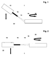
- the Fig. 1 and 2 show an exemplary apparatus for carrying out an exemplary method according to the invention.
- the apparatus 1 shown in the figures comprises or is formed by an HVOF burner 10.
- a component 12 of a gas turbine engine in particular component 12 of an aircraft engine, is also shown.
- the HVOF burner 10 and the component 12 of the aircraft engine are also shown.
- powder is provided which consists of ceramic or has ceramic.
- This powder which is not shown in the figures, is supplied by means of the apparatus 1, such that it is fed into the hot gas jet 14, which is formed by means of the gas emerging from the nozzle 16 of the burner 10.
- the ceramic powder is used in one step of the process, which in Fig. 1 is shown on a surface 18 of the component 12 applied to radiate this or activate or roughen. Consequently, in Fig. 1 surface activation or surface roughening or surface blasting is shown.
- the component 12 is rotated during blasting, as indicated for example by the arrow 20. Furthermore, it is provided in particular - which is schematically indicated by the arrow 22 - that a Abzeilen of the component takes place, so in particular the component 1 is traversed line by line and each row is rotated according to the arrow 20.
- Fig. 2 shows the design according to Fig. 1 , where in Fig. 2 which is shown at the beam subsequent ⁇ -coating.
- the coating is carried out by means of rotation according to the arrow 20 of the component 1 and by means of lines corresponding to the arrow 22nd
- the device also has a holding device or receiving device for receiving or holding a component 12.
- a coating material in particular in the form of powder
- the hot gas jet 14 is supplied, wherein it is provided in particular that of the step accordingly Fig. 1 according to the step Fig. 2 the powder strand is switched accordingly.
- the device 1 provision is made, in particular, for the device 1 to have a plurality of powder conveyors, and a switching device for switching from a powder conveyor, which is intended for the conveyance of ceramic powder for blasting, to a powder conveyor, which is provided for conveying powder for the coating.
Landscapes
- Chemical & Material Sciences (AREA)
- Engineering & Computer Science (AREA)
- Mechanical Engineering (AREA)
- Chemical Kinetics & Catalysis (AREA)
- Materials Engineering (AREA)
- Metallurgy (AREA)
- Organic Chemistry (AREA)
- Physics & Mathematics (AREA)
- Plasma & Fusion (AREA)
- Coating By Spraying Or Casting (AREA)
- Nozzles (AREA)
- Application Of Or Painting With Fluid Materials (AREA)
Applications Claiming Priority (1)
| Application Number | Priority Date | Filing Date | Title |
|---|---|---|---|
| DE102007031602A DE102007031602A1 (de) | 2007-07-06 | 2007-07-06 | Verfahren zum Bearbeiten einer Oberfläche eines Bauteils eines Flugtriebwerks |
Publications (2)
| Publication Number | Publication Date |
|---|---|
| EP2014415A1 true EP2014415A1 (fr) | 2009-01-14 |
| EP2014415B1 EP2014415B1 (fr) | 2011-08-03 |
Family
ID=39739233
Family Applications (1)
| Application Number | Title | Priority Date | Filing Date |
|---|---|---|---|
| EP08011156A Ceased EP2014415B1 (fr) | 2007-07-06 | 2008-06-19 | Procédé de traitement d'une surface d'un composant d'un turbine à gas |
Country Status (2)
| Country | Link |
|---|---|
| EP (1) | EP2014415B1 (fr) |
| DE (1) | DE102007031602A1 (fr) |
Cited By (2)
| Publication number | Priority date | Publication date | Assignee | Title |
|---|---|---|---|---|
| WO2011131166A1 (fr) | 2010-04-22 | 2011-10-27 | Mtu Aero Engines Gmbh | Procédé de traitement d'une surface d'un composant |
| US9347136B2 (en) | 2014-01-31 | 2016-05-24 | Pratt & Whitney Canada Corp. | Method for applying a coating to a substrate |
Families Citing this family (2)
| Publication number | Priority date | Publication date | Assignee | Title |
|---|---|---|---|---|
| DE102009052946A1 (de) | 2009-11-12 | 2011-05-19 | Mtu Aero Engines Gmbh | Verfahren und Vorrichtung zur Bauteilbeschichtung |
| DE102012023212B3 (de) * | 2012-11-28 | 2014-01-30 | Wieland-Werke Ag | Elektrisch leitendes Bauteil mit verbesserter Haftung und Verfahren zu seiner Herstellung, sowie zur Herstellung eines Werkstoffverbunds |
Citations (4)
| Publication number | Priority date | Publication date | Assignee | Title |
|---|---|---|---|---|
| US6383658B1 (en) * | 1999-11-18 | 2002-05-07 | General Electric Company | Thermally sprayed coatings having an interface with controlled cleanliness |
| EP1507018A1 (fr) * | 2003-08-15 | 2005-02-16 | Walbar Metals, Inc. | Procédé de traitment d'une turbine de gaz préalable du revêtement |
| EP1588992A1 (fr) * | 2004-04-22 | 2005-10-26 | General Electric Company | Compositions céramiques à base d'oxydes mixtes pour des revêtements de barrières thermiques de basse conductivité thermique |
| US20070116890A1 (en) * | 2005-11-21 | 2007-05-24 | Honeywell International, Inc. | Method for coating turbine engine components with rhenium alloys using high velocity-low temperature spray process |
-
2007
- 2007-07-06 DE DE102007031602A patent/DE102007031602A1/de not_active Withdrawn
-
2008
- 2008-06-19 EP EP08011156A patent/EP2014415B1/fr not_active Ceased
Patent Citations (4)
| Publication number | Priority date | Publication date | Assignee | Title |
|---|---|---|---|---|
| US6383658B1 (en) * | 1999-11-18 | 2002-05-07 | General Electric Company | Thermally sprayed coatings having an interface with controlled cleanliness |
| EP1507018A1 (fr) * | 2003-08-15 | 2005-02-16 | Walbar Metals, Inc. | Procédé de traitment d'une turbine de gaz préalable du revêtement |
| EP1588992A1 (fr) * | 2004-04-22 | 2005-10-26 | General Electric Company | Compositions céramiques à base d'oxydes mixtes pour des revêtements de barrières thermiques de basse conductivité thermique |
| US20070116890A1 (en) * | 2005-11-21 | 2007-05-24 | Honeywell International, Inc. | Method for coating turbine engine components with rhenium alloys using high velocity-low temperature spray process |
Cited By (5)
| Publication number | Priority date | Publication date | Assignee | Title |
|---|---|---|---|---|
| WO2011131166A1 (fr) | 2010-04-22 | 2011-10-27 | Mtu Aero Engines Gmbh | Procédé de traitement d'une surface d'un composant |
| DE102010017859A1 (de) | 2010-04-22 | 2011-10-27 | Mtu Aero Engines Gmbh | Verfahren zum Bearbeiten einer Oberfläche eines Bauteils |
| US20130034661A1 (en) * | 2010-04-22 | 2013-02-07 | Mtu Aero Engines Gmbh | Method for processing a surface of a component |
| US9347136B2 (en) | 2014-01-31 | 2016-05-24 | Pratt & Whitney Canada Corp. | Method for applying a coating to a substrate |
| US9758875B2 (en) | 2014-01-31 | 2017-09-12 | Pratt & Whitney Canada Corp. | Method for applying a coating to a substrate |
Also Published As
| Publication number | Publication date |
|---|---|
| DE102007031602A1 (de) | 2009-01-08 |
| EP2014415B1 (fr) | 2011-08-03 |
Similar Documents
| Publication | Publication Date | Title |
|---|---|---|
| DE69730245T2 (de) | Verfahren zur behandlung von metallteilen | |
| EP2560789B1 (fr) | Procédé de traitement d'une surface d'un composant | |
| EP2298962B1 (fr) | Pulverisation à froid de revêtements contenant des oxydes | |
| EP3789512A1 (fr) | Installation et procédé de revêtement de pièces | |
| DE102008024313A1 (de) | Verfahren zur Vorkonditionierung einer zu beschichtenden Oberfläche | |
| EP2788520A1 (fr) | Procédé de revêtement d'un substrat | |
| EP2576863B1 (fr) | Procédé de réalisation d'une couche par injection de gaz froid et utilisation d'une telle couche | |
| EP2014415B1 (fr) | Procédé de traitement d'une surface d'un composant d'un turbine à gas | |
| EP3463678B1 (fr) | Procede de revetement | |
| DE10319481A1 (de) | Lavaldüse für das thermische Spritzen und das kinetische Spritzen | |
| DE102009052946A1 (de) | Verfahren und Vorrichtung zur Bauteilbeschichtung | |
| EP2533911B1 (fr) | Procédé d'élimination de l'excès de projection de couches de revêtement par projection thermique | |
| EP2785491B1 (fr) | Procédé pour réparer une aube directrice variable | |
| EP3647615A1 (fr) | Composant de palier à rouleaux ou lisse métallique | |
| EP1506816B1 (fr) | Buse de Laval pour la pulvérisation thermique et cinétique | |
| WO2013083672A1 (fr) | Dispositif de projection plasma et procédé de revêtement | |
| EP1942387A1 (fr) | Concept de revêtement pour une installation APS/HVOF dotée de 2 robots | |
| EP2714963A1 (fr) | Procédé d'injection de gaz froid présentant une meilleure adhérence et une porosité de couche réduite | |
| DE4124084A1 (de) | Verfahren zum entfernen von auf rohren befindlichen beschichtungen | |
| EP1350862A1 (fr) | Procédé et apparail d'application thermique d'un revêtement sur une surface | |
| DE102011087159B3 (de) | Haftgrundvorbereitung für das Kaltgasspritzen und Kaltgasspritzvorrichtung | |
| WO2015158458A1 (fr) | Installation et procédé pour le revêtement métallique d'une paroi d'un alésage | |
| EP1652956B1 (fr) | Dispositif et procédé de pulvérisation thermique | |
| DE102023136185A1 (de) | Bremsscheibe, Fortbewegungsmittel und Verfahren zur Beschichtung einer Bremsscheibe | |
| DE1758548A1 (de) | Verfahren und Vorrichtung zur Verbesserung der Erkennbarkeit von Oberflaechenfehlern von Stranggusserzeugnissen |
Legal Events
| Date | Code | Title | Description |
|---|---|---|---|
| PUAI | Public reference made under article 153(3) epc to a published international application that has entered the european phase |
Free format text: ORIGINAL CODE: 0009012 |
|
| AK | Designated contracting states |
Kind code of ref document: A1 Designated state(s): AT BE BG CH CY CZ DE DK EE ES FI FR GB GR HR HU IE IS IT LI LT LU LV MC MT NL NO PL PT RO SE SI SK TR |
|
| AX | Request for extension of the european patent |
Extension state: AL BA MK RS |
|
| 17P | Request for examination filed |
Effective date: 20090625 |
|
| 17Q | First examination report despatched |
Effective date: 20090805 |
|
| AKX | Designation fees paid |
Designated state(s): DE FR GB |
|
| GRAP | Despatch of communication of intention to grant a patent |
Free format text: ORIGINAL CODE: EPIDOSNIGR1 |
|
| GRAS | Grant fee paid |
Free format text: ORIGINAL CODE: EPIDOSNIGR3 |
|
| GRAA | (expected) grant |
Free format text: ORIGINAL CODE: 0009210 |
|
| AK | Designated contracting states |
Kind code of ref document: B1 Designated state(s): DE FR GB |
|
| REG | Reference to a national code |
Ref country code: GB Ref legal event code: FG4D Free format text: NOT ENGLISH |
|
| REG | Reference to a national code |
Ref country code: DE Ref legal event code: R096 Ref document number: 502008004350 Country of ref document: DE Effective date: 20110929 |
|
| PLBE | No opposition filed within time limit |
Free format text: ORIGINAL CODE: 0009261 |
|
| STAA | Information on the status of an ep patent application or granted ep patent |
Free format text: STATUS: NO OPPOSITION FILED WITHIN TIME LIMIT |
|
| 26N | No opposition filed |
Effective date: 20120504 |
|
| REG | Reference to a national code |
Ref country code: DE Ref legal event code: R097 Ref document number: 502008004350 Country of ref document: DE Effective date: 20120504 |
|
| REG | Reference to a national code |
Ref country code: GB Ref legal event code: 732E Free format text: REGISTERED BETWEEN 20131114 AND 20131120 |
|
| REG | Reference to a national code |
Ref country code: FR Ref legal event code: PLFP Year of fee payment: 9 |
|
| REG | Reference to a national code |
Ref country code: FR Ref legal event code: PLFP Year of fee payment: 10 |
|
| REG | Reference to a national code |
Ref country code: FR Ref legal event code: PLFP Year of fee payment: 11 |
|
| PGFP | Annual fee paid to national office [announced via postgrant information from national office to epo] |
Ref country code: GB Payment date: 20220623 Year of fee payment: 15 Ref country code: DE Payment date: 20220621 Year of fee payment: 15 |
|
| PGFP | Annual fee paid to national office [announced via postgrant information from national office to epo] |
Ref country code: FR Payment date: 20220622 Year of fee payment: 15 |
|
| REG | Reference to a national code |
Ref country code: DE Ref legal event code: R119 Ref document number: 502008004350 Country of ref document: DE |
|
| GBPC | Gb: european patent ceased through non-payment of renewal fee |
Effective date: 20230619 |
|
| PG25 | Lapsed in a contracting state [announced via postgrant information from national office to epo] |
Ref country code: DE Free format text: LAPSE BECAUSE OF NON-PAYMENT OF DUE FEES Effective date: 20240103 Ref country code: GB Free format text: LAPSE BECAUSE OF NON-PAYMENT OF DUE FEES Effective date: 20230619 |
|
| PG25 | Lapsed in a contracting state [announced via postgrant information from national office to epo] |
Ref country code: FR Free format text: LAPSE BECAUSE OF NON-PAYMENT OF DUE FEES Effective date: 20230630 |