EP0523631A2 - Elektrophotographisches Druckgerät - Google Patents
Elektrophotographisches Druckgerät Download PDFInfo
- Publication number
- EP0523631A2 EP0523631A2 EP92111999A EP92111999A EP0523631A2 EP 0523631 A2 EP0523631 A2 EP 0523631A2 EP 92111999 A EP92111999 A EP 92111999A EP 92111999 A EP92111999 A EP 92111999A EP 0523631 A2 EP0523631 A2 EP 0523631A2
- Authority
- EP
- European Patent Office
- Prior art keywords
- toner
- printing machine
- electrophotographic printing
- set forth
- electrically conductive
- Prior art date
- Legal status (The legal status is an assumption and is not a legal conclusion. Google has not performed a legal analysis and makes no representation as to the accuracy of the status listed.)
- Granted
Links
Images

Classifications
-
- G—PHYSICS
- G03—PHOTOGRAPHY; CINEMATOGRAPHY; ANALOGOUS TECHNIQUES USING WAVES OTHER THAN OPTICAL WAVES; ELECTROGRAPHY; HOLOGRAPHY
- G03G—ELECTROGRAPHY; ELECTROPHOTOGRAPHY; MAGNETOGRAPHY
- G03G15/00—Apparatus for electrographic processes using a charge pattern
- G03G15/22—Apparatus for electrographic processes using a charge pattern involving the combination of more than one step according to groups G03G13/02 - G03G13/20
- G03G15/226—Apparatus for electrographic processes using a charge pattern involving the combination of more than one step according to groups G03G13/02 - G03G13/20 where the image is formed on a dielectric layer covering the photoconductive layer
- G03G15/227—Apparatus for electrographic processes using a charge pattern involving the combination of more than one step according to groups G03G13/02 - G03G13/20 where the image is formed on a dielectric layer covering the photoconductive layer the length of the inner surface of the dielectric layer being greater than the length of the outer surface of the photoconductive layer
-
- G—PHYSICS
- G03—PHOTOGRAPHY; CINEMATOGRAPHY; ANALOGOUS TECHNIQUES USING WAVES OTHER THAN OPTICAL WAVES; ELECTROGRAPHY; HOLOGRAPHY
- G03G—ELECTROGRAPHY; ELECTROPHOTOGRAPHY; MAGNETOGRAPHY
- G03G15/00—Apparatus for electrographic processes using a charge pattern
- G03G15/22—Apparatus for electrographic processes using a charge pattern involving the combination of more than one step according to groups G03G13/02 - G03G13/20
- G03G15/34—Apparatus for electrographic processes using a charge pattern involving the combination of more than one step according to groups G03G13/02 - G03G13/20 in which the powder image is formed directly on the recording material, e.g. by using a liquid toner
- G03G15/344—Apparatus for electrographic processes using a charge pattern involving the combination of more than one step according to groups G03G13/02 - G03G13/20 in which the powder image is formed directly on the recording material, e.g. by using a liquid toner by selectively transferring the powder to the recording medium, e.g. by using a LED array
-
- G—PHYSICS
- G03—PHOTOGRAPHY; CINEMATOGRAPHY; ANALOGOUS TECHNIQUES USING WAVES OTHER THAN OPTICAL WAVES; ELECTROGRAPHY; HOLOGRAPHY
- G03G—ELECTROGRAPHY; ELECTROPHOTOGRAPHY; MAGNETOGRAPHY
- G03G2215/00—Apparatus for electrophotographic processes
- G03G2215/04—Arrangements for exposing and producing an image
- G03G2215/0497—Exposure from behind the image carrying surface
Definitions
- the present invention relates to an electrophotographic printing machine which forms images through a method wherein a toner image is formed by developing an electrostatic latent image formed on a surface of a photoreceptor using a photoconductive phenomenon, thereafter, transferred to a copying material and made permanent on the copying material.
- an electrophotography has been generally used, i.e., an application of the Carlson process.
- the principle of the electrophotography is described in detail in reference to Fig. 6 through an example of a normal developing system adopted in photocopying machines.
- a charger 32, an exposure unit 33, a developer unit 34, a transfer unit 35, a fuser 36, a cleaner 37, and an eraser 38 are provided in this order along the circumference of a photoreceptor drum 31 having a photosensitive layer formed on the surface thereof as shown in Fig. 6.
- the surface of the photoreceptor drum 31 is uniformly charged by the charger 32 in a dark place.
- an original image is illuminated on the surface of the photoreceptor drum 31 by the exposure unit 33 so as to remove charges from the illuminated portion, thereby forming an electrostatic latent image on the surface of the photoreceptor drum 31.
- a toner 39 is made to adhere the electrostatic latent image, the toner 39 being charged by applying thereon a charge having a polarity opposite to the charge on the photoreceptor drum 31 in the developer unit 34, thereby forming a visible image of the toner 39.
- a copying material 40 is superposed on the visible image.
- a corona-discharging is carried out by the transfer unit 35 from the back surface of the copying material 40 so as to apply a charge having a polarity opposite to the toner 39.
- the toner image is transferred to the copying material 40.
- the transferred toner image is made permanent on the copying material 40.
- a residual toner 39a remaining on the photoreceptor drum 31 after the transfer is removed by a cleaner 37.
- a corona discharger is adopted for charging the photoreceptor drum 31 or transferring the toner 39 to the copying material 40.
- a corona discharger is adopted, a high voltage of several kV is required.
- it is likely to be affected by a change in the ambient condition, for example, a change in the charge amount on the surface of the photoreceptor drum 31 due to a temperature change.
- ozone produced in the process of corona charging results in the problem in terms of an environmental health.
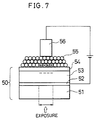
- a photoreceptor 50 is desirably arranged such that a transparent electrically conductive layer 52 made of In2O2, etc., a photoconductive layer 53 made of Se etc., and a dielectric layer 54 made of polyethlene terephtalate film, are laminated in this order on a transparent base 51 made of glass or the like.
- the charged toner 55 and the charge injected through the transparent electrically conductive layer 52 become being attracted from one another having the dielectric layer 54 in between by making pairs with charges having opposite polarities. In this way, even when the magnet 56 is moved away from the photoconductor 50, the toner 55 at the exposed portion remains on the surface of the photoconductor 50.
- the discussed method enables a toner image to be formed on the surface of the photoconductor 50 without using the corona charging.
- the toner image is transferred from the surface of the photoconductor 50 to the surface of the copying material as in the case of the Carlson process. Thereafter, the toner is transported to the fuser which heats up the toner to be melted, thereby the toner image is permanently affixed to the copying material.
- the photoconductor 50 arranged such that the surface of the transparent base 51 whereon the transparent electrically conductive layer 52, the photoconductive layer 53, and the insulating layer 54 are laminated in this order may be damaged by repeating the image forming process, especially by the repetitive sliding contact of the toner 55 with the insulating layer 54 provided on the periphery surface, or by the blade-shaped cleaner for removing the residual toner on the surface of the insulating layer 54 after the transfer.
- an adhesive characteristic to the surface of the photosensitive layer 53, or solubility with respect to solvent needs to be considered in selecting the material.
- the material to be used in the insulating layer 54 is restricted such as polyethlene terephtalate, and the material excellent in its hard-wearing properties, may not be selected. This presents the problem of a high deterioration rate of the dielectric layer 54 which shortens the life of the photoconductor 50.
- An object of the present invention is to provide an electrophotographic printing machine capable of providing longer life of constituting components such as a photoreceptor drum which enables an image to be formed without using corona-charging.
- Another object of the present invention is to trim a size of an electrophotographic printing machine or to provide an electrophotographic printing machine capable of improving an image quality.
- an electrophotographic printing machine in accordance with the present invention is characterized in comprising: photoreceptor means including a cylindrical base having an electrically conductive layer and a photoconductive layer laminated in this order on a periphery surface thereof; dielectric moving means wound around a surface of the photoreceptor means and firmly adhering thereto for integrally moving therewith; electrically conductive toner support means for applying an electrically conductive toner on the surface of the moving means, the support means being provided in a vicinity of the surface of the moving means in a contact area between the moving means and the photoreceptor means; voltage application means for applying voltage across the toner support means and the electrically conductive layer; and exposure means for exposing the photoconductive layer in the contact area, wherein the exposure means exposes the photoconductive layer in the contact area while applying voltage across the toner support means and the electrically conductive layer, thereby forming a toner image on the surface of the moving means.
- the electrically conductive layer and photoconductive layer are sequentially formed on the periphery surface of the cylindrical base, and the dielectric moving means is in tight contact with the photoconductive layer. Further, the electrically conductive toner being supported by the toner support means adheres to the surface of the moving means. In this state, voltage is applied between the toner support means and the electrically conductive layer of photoreceptor means, whereby charges having opposite polarity from one another are laminated respectively on the electrically conductive toner and the electrically conductive layer with the photoconductive layer and the dielectric moving means interposed therebetween. Further, the photoconductive layer is exposed by the exposure means, thereby lowering the resistance of the exposed portion of the photoconductive layer.
- the charge having an opposite polarity to the charge laminated on the leading edge of the electrically conductive toner is injected to the moving means side of the photoconductive layer, thereby forming an electrostatic latent image.
- the electrically conductive toner corresponding to the electrostatic latent image is affected by strong Coulomb force that occurred between them. Therefore, the Coulomb force between the electrostatic latent image and the toner is set greater than the holding power for holding the toner on the toner support means, for example, by controlling voltage to be applied between the toner support means and the electrically conductive layer, or the holding power for holding the toner on the toner support means. In this way, when the toner support means is moved away from the moving means, the toner image corresponding to the electrostatic latent image is formed on the surface of the moving means.
- the toner image is formed on the moving means which is separately provided from the photoreceptor means, the surface of the photoreceptor means can be prevented from being damaged by the toner adhering thereto or cleaner in contact therewith in removing the toner.
- the moving means having the toner image formed on the surface thereof is also provided separately from the photoreceptor means. Therefore, the material to be used for the moving means is not necessarily restricted by solubility with respect to solvent used in coating the photoconductive layer on the surface of the photoreceptor, or the like. The material excellent in its strength, hard-wearing properties, can be used as long as those can be formed with an adequate resistivity and thickness.
- the deterioration rate of the moving means as well as the photoreceptor means can be reduced, thereby providing a longer life of the whole apparatus. Moreover, it is possible to replace only the moving means with new moving means without replacing the photoreceptor means. This also contributes to provide a longer life of the apparatus.
- the electrophotographic printing machine having the described configuration may be arranged to further comprise: heating means for melting by a heat treatment the toner of the toner image formed on the surface of the moving means after the photoreceptor means passes a exposure area; and pressure means for pressing a superposed portion between the copying material and the moving means toward the heating means, the pressure means being disposed confronting the heating means so as to have the moving means and the copying material being transported thereon interposed in between.
- the heating means and the pressure means are provided so as to face one another having the moving means interposed in between.
- the moving means is provided separately from the photoreceptor means, therefore, the toner image formed on the surface of the moving means can be transferred up to a position apart from the photoreceptor means. In this position, the heating means and the pressure means can be disposed so as to face one another having the moving means interposed in between.
- the moving means is separately provided from the photoreceptor means, the material excellent in its heat resistance can be selected for the moving means considering the fusing temperature of the toner.
- the toner image can be transferred from the moving means to the copying material, and the toner image is made permanent on the copying material.
- the discussed method does not require the transfer unit composed of the corona discharger, etc. This permits to trim the size of the apparatus. Moreover, with this method, the transferring and fusing processes are carried out simultaneously. Therefore, the turbulence of the toner image is reduced, the better quality of the toner image is attained compared with the conventional case where after being transferred to the copying material, the toner image is further transported to the fuser to be permanently affixed to the copying material.
- the electrophotographic printing machine in accordance with the present invention may also be arranged such that the cylindrical base and the electrically conductive layer of the photoreceptor means are made of a transparent material, and the exposure means is disposed in the photoreceptor means wherein a light beam is projected onto the photoconductive layer through the cylindrical base and the electrically conductive layer, thereby exposing the photoconductive layer.
- Figs. 1 through 5 show one embodiment of the present invention.
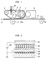
- Fig. 1 is a typical depiction showing a schematic configuration of an electrophotographic printing machine.
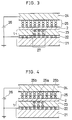
- Fig. 2 is an enlarged cross-sectional view explaining a principle in forming image with the machine of Fig. 1.
- Fig. 3 is an enlarged cross-sectional view showing a change when an exposing operation is carried out with the state shown in Fig. 2.
- Fig. 4 is an enlarged cross-sectional view showing a change from the state of Fig. 3 when the exposing operation is stopped.
- Fig. 5 is an enlarged cross-sectional view showing a change from the state of Fig. 4 when a developer unit is separated from the surface of the photoreceptor drum.
- Figs. 6 and 7 show the prior art.
- Fig. 6 is a typical depiction showing a configuration of an image forming apparatus adopting a conventional Carlson process.
- Fig. 7 is a typical depiction of a cross-sectional view explaining a toner image forming system without uniformly charging an entire surface of the photoconductive layer.
- an electrophotographic printing machine in accordance with the present embodiment comprises a cylindrical photoreceptor drum 1 (photoreceptor means) and a dielectric belt 2 (moving means) having wound around thereto.
- the photoreceptor drum 1 is arranged as follows.
- a transparent electrically conductive layer 22 constituted of a thin film made of SnO2 and a photoconductive layer 23 are formed in this order on a surface of a transparent support 21 (cylindrical base) made of glass.
- the photoconductive layer 23 is made of amorphous silicone (a - Si) with a thickness of substantially 20 ⁇ m.
- the dielectric belt 2 is made of film material including mainly a polyimide which is superior in its mechanical strength and heat resistance.
- the belt 2 is belt-shaped with no end with a thickness of substantially 20 ⁇ m.
- Table 1 representative characteristics of polyimide film characteristics measured value measuring method tensile force 35.8 kg/mm2 ASTM D 882 extension percentage 24% ASTM D 882 extension elastic modulus (extended by 1%) 660 kg/mm2 ASTM D 882 coefficient of friction 0.3 for steel ball creep 25 °C 0.07% 2 .4kg/mm2 70 °C 0.32% 24 hours specific gravity 1.44 - heat decomposition temperature (5% loss in weight) 635 °C TGM 5 °C/min coefficient of linear expansion (25 -180 °C) 1 ⁇ 10 ⁇ 5/°C TMA 5 °C/min surface resistivity 1015 ⁇ ASTM D 257
- the dielectric belt 2 belts the photoreceptor drum 1, a heater 3 (to be described later), and a tension roller 4 so as to surround them from outside.
- the dielectric belt 2 also receives appropriate strength of tensile force from the tension roller so as to be in tight contact with substantially a right hand side semi-circumference of the photoreceptor drum 1.
- the heater 3 is located on the left hand and slightly lower side of the photoreceptor drum 1.
- the tension roller 4 is placed on the upper left side of the heater 3.
- an exposure means 5 is placed inside the photoreceptor drum 1. Further, the developer unit 6 storing toner (to be described later), is provided confronting the exposure unit 5 with a contact area between the dielectric belt 2 and the photoreceptor drum 1 interposed in between.
- the exposure unit 5 is arranged so as to include a light emitting diode (LED) alley wherein a lens having a short focal distance is combined into the LED. Further, the exposure unit 5 projects a light beam in response to an exposure pattern signal from an exposure controlling unit (not shown) towards a developer unit 6 so as to be converged onto the photoconductive layer 23 through the transparent support 21 of the photoreceptor drum 1.
- LED light emitting diode
- the heater 3 is disposed within a lower-side travel area between the exposure unit 5 and the tension roller 4 and in contact with an inner surface of the dielectric belt 2.
- the heater 3 is provided for heating up the toner to be melted, the toner adhering to the surface of the dielectric belt 2.
- the heater 3 is arranged to be a ceramic heater having a Mo series resistance heater and a glass coat laminated thereon in this order by printing. Further, the heater 3 is arranged such that a temperature of a heating surface thereof is rapidly raised up to a predetermined heating temperature by applying electric power to the resistance heater. The heating surface is in direct contact with the inner surface of dielectric belt 2.
- a pressurizing roller 7 rotating while applying pressing force towards the heater 3 is disposed under the heater 3.
- a sheet-like copying material 9 is fed by a pair of transport rollers 8 between the heater 3 and the pressurizing roller 7.
- the copying material 9 is transported in the transporting direction while being welded with pressure to the bottom side of the dielectric belt 2 by the pressurizing roller 7.
- normally paper sheet is used for the copying material 9; however, it is not necessarily limited to this type of copying material.
- a pair of erasers 10 is disposed having the dielectric belt 2 in between.
- Each of the erasers 10 connected to ground has a blush section at a leading edge thereof made of carbon conjugate fiber. The leading edges of the blush sections are respectively in sliding contact with inner and outer surfaces of the dielectric belt 2 while the dielectric belt 2 being traveled, thereby removing the charge adhering thereto.
- the photoreceptor drum 1 When the copying material 9 is fed by the transport rollers 8 in the direction of arrow A, at the same time, the photoreceptor drum 1 is driven so as to rotate in a clockwise direction, i.e., in the direction of arrow B in the figure at the circumferential speed same as the transporting speed of the copying material 9. Further, the dielectric belt 2 wound around the photoreceptor drum 1 travels in the direction of arrow C at the same speed as the circumferential speed of the photoreceptor drum 1.
- the process for exposure for forming images is executed as follows. LED corresponding to a predetermined image pattern is selected in order, and a light beam is projected from the exposure unit 5 onto the photoconductive layer 23 of the photoreceptor drum 1, whereon an electrostatic latent image is formed.
- the process for development is executed so as to visualize the electrostatic latent image with toner. The detailed description will be given hereinbelow referring to Figs. 2 through 5.
- a developer electrode 24 (toner hold means) shown in Fig. 2 is provided.
- the developer electrode 24 is disposed in a vicinity of the surface of the dielectric belt 2 integrally moving with the surface of the photoreceptor drum 1 by being in direct contact therewith. Further, the developer electrode 24 is connected to magnetic field generation means (not shown) in the developer unit 6.
- a permanent magnet or electro-magnet is preferably used for the magnetic field generation means.
- An electrically conductive magnetic toner 25 is made to adhere to the surface of the developer electrode 24 by magnetic field generated by the magnetic field generation means, thereby forming a magnetic blush.
- the toner 25 at the leading edge side of the blush is in sliding contact with the surface of the dielectric belt 2.
- DC voltage in the range of 100V to 300V is applied between the developer electrode 24 and the transparent electrically conductive layer 22 of the photoreceptor drum 1 by a power supply 26, having the developer electrode 24 side as a negative side.
- a power supply 26 having the developer electrode 24 side as a negative side.
- a light beam is projected according to the image pattern onto the photoconductive layer 23 from the side of the transparent support 21.
- a pair of a positive hole and an electron is generated in an illuminated area 27 on the photoconductive layer 23 as shown in Fig. 3.
- the positive hole moves towards the dielectric belt 2; whereas, the electron moves towards the transparent electrically conductive layer 22 and flows thereinto.
- an exposure area contact toner 25a exists at a position confronting the trapped positive hole with the dielectric belt 2 in between.
- a greater number of negative charge are injected and have greater effect from strong Coulomb force than the adjacent non-exposure area contact toner 25b.
- the developer electrode 24 With the rotation of the photoreceptor drum 1, the developer electrode 24 gradually moves away from the exposure area. Then, the Coulomb force between the exposure area contact toner 25a and the positive hole in the photoconductive layer 23 is stronger than the magnetic force from the developer electrode 24 side. As a result, as shown in Fig. 5, the exposure area contact toner 25a is separated from the developer electrode 24 side and maintained at the position adhering to the surface of the dielectric belt 2. The exposure area contact toner 25a and the trapped positive hole in the photoconductive layer 23 becomes being attracted one another by the injected negative charge, thereby forming a stable toner image. On the other hand, the non-exposure area contact toner 25b is attracted towards the developer electrode 24 side by the magnetic force, thereby being separated and moved away from the dielectric belt 2 with the developer electrode 24.
- the toner image on the dielectric belt 2 is transported between the heater 3 and the pressurizing roller 7 shown in Fig. 1.
- the copying material 9 is superposed onto the dielectric belt 2. Therefore, the transfer and fusing processes of toner to the copying material can be carried out simultaneously.
- the copying material 9 while being fed between the heater 3 and pressurizing roller 7, the copying material 9 is heated and pressed by them, and the heater 3 applies heat to the exposure area contact toner 25a to be melted.
- the dielectric belt 2 is superior to the copying material 9 such as a paper sheet in its high mold release characteristic with respect to the toner 25a being melted by a heat treatment. For this reason, almost all the toner 25a on the dielectric belt 2 is transferred onto the copying material 9 and made to permanently adhere thereto. This means that cleaning process for removing the residual toner on the dielectric belt 2 is not required with the above arrangement.
- those material having a high mold release characteristic with respect to the melted toner 25a such as fluoroplastic is desirably coated on the surface of the dielectric belt 2.
- a portion of the dielectric belt 2 whereon the transfer and fusing processes have been completed is fed to the position where the the eraser 10 is located through the tension roller 4.
- the problem may arise since static electricity is likely to be increased on the surface of the dielectric belt 2 due to a mechanical friction, etc. This may be a problem in forming image in the process of exposure.
- the eraser 10 is provided for removing the residual charge. Thereafter, the processes of exposure and development are repeated on the photoreceptor drum 1, thereby successively forming images.
- a drum photosensitive layer eraser unit 11 for projecting a light beam onto the photoconductive layer 23 of the photoreceptor drum 1 is additionally provided outside the photoreceptor drum 1 within the space surrounded by the dielectric belt 2.
- an image can be formed without providing the charger 32, transfer unit 35 and cleaner 37 all required in the previously mentioned Carlson process. This permits to trim the size of the apparatus. Moreover, since the corona discharger is not used, the image forming apparatus does not require the high voltage power supply, nor generate ozone.
- the photoconductive layer 23 is disposed on the surface of the photoreceptor drum 1.
- the dielectric belt 2 separately provided from the photoreceptor drum 1 is hung on the surface thereof, further, the toner image is formed on the surface of the dielectric belt 2. Therefore, the photoconductive layer 23 formed on the surface of the photoreceptor drum 1 can be prevented from being damaged due to the toner or the cleaner for removing the residual charge in sliding contact therewith.
- the material to be used for the belt 2 is not restricted by solubility with respect to solvent used in coating the photoconductive layer on the surface of the photoconductor, or the like.
- the material excellent in its strength, hard-wearing properties, can be used as long as those can be formed with an adequate resistivity and thickness.
- the stronger material for the dielectric belt 2 the deterioration rate of the dielectric belt 2 as well as the photoreceptor drum 1 can be reduced, thereby providing a longer life of the whole apparatus.
- the dielectric belt 2 is provided separately from the photoreceptor drum 1, therefore, the toner image formed on the surface of the dielectric belt 2 can be transferred up to a position apart from the photoreceptor drum 1. In this position, the heater 3 and the pressurizing roller 7 can be disposed so as to have the dielectric belt 2 interposed in between. Moreover, since the dielectric belt 2 is separately provided from the photoreceptor drum 1, the material excellent in its heat resistance can be selected for the dielectric belt 2 considering the fusing temperature of the toner. In this way, by pressing the copying material 9 onto the toner being melted on the surface of the dielectric belt 2, the toner image can be transferred from the dielectric belt 2 to the copying material 9 and made to permanently adhere thereto.
- the discussed method does not require the transfer unit composed of the corona discharger, etc., that required in the case of conventional Carlson process, thereby permitting to trim the size of the apparatus. Moreover, with this method, the transfer and fusing processes are carried out simultaneously. Therefore, compared with the conventional case where the toner image is transported to the fuser after being transferred to the copying material, to be permanently affixed thereto, the turbulence of the toner image is controlled, and the better quality of the toner image is attained.
- the transfer and fusing processes of the toner image can be carried out simultaneously, the shorter transport distance of the copying material 9 is required, and thus time required for forming image is also reduced, thereby reducing the occurrence of the copying material being jammed in the apparatus.
- the pair of eraser 10 for removing the residual charge on the dielectric belt 2 is disposed between the photoreceptor drum 1 and the tension roller 4, and the blushes thereof are in sliding contact with the dielectric belt 2 being interposed by the blushes.
- the residual charge can be quickly and accurately removed.
- This also enables the clear image to be formed without having a turbulence in the toner image due to the residual charge after the exposure.
- the image forming speed of the dielectric belt 2 is also improved by, for example, increasing the travelling speed of the dielectric belt 2.
- the dielectric magnetic toner 25 is used in the above embodiment; however, other types of toner than those used in the electrophotographic printing method is used as well for the development.
- the dielectric belt 2 made of a polyimide film has been used in the above embodiment.
- Other material may be used as long as those can be formed in a belt shape with no end with an appropriate mechanical strength.
- the material other than the polyimide film film material including mainly a polyamide is preferably used.
- the electrophotographic printing machine in accordance with the present invention is arranged so as to include photoreceptor means including a cylindrical base having an electrically conductive layer and a photoconductive layer laminated in this order on a periphery surface thereof; moving means wound around a surface of the photoreceptor means and firmly adhering thereto for integrally moving therewith; electrically conductive toner hold means for applying an electrically conductive toner on the surface of the moving means, the support means being provided in a vicinity of the surface of the dielectric belt in a contact area between the moving means and the photoreceptor means; voltage application means for applying voltage across the toner hold means and the electrically conductive layer; and exposure means for exposing the photoconductive layer in the contact area, wherein the exposure means exposes the photoconductive layer in the contact area while applying voltage across the support means and the electrically conductive layer, thereby forming a toner image on the surface of the moving means.
- photoreceptor means including a cylindrical base having an electrically conductive layer and a photoconductive layer laminate
- the photoconductive layer formed on the surface of the photoreceptor means can be prevented from being damaged due to the toner or the cleaner for removing the residual charge in sliding contact therewith.
- the material to be used for the moving means is not restricted by solubility with respect to solvent used in coating the photoconductive layer on the surface of the photoconductor means, or the like. The material excellent in its strength, hard-wearing properties, can be used as long as those can be formed with an adequate resistivity and thickness.
- the deterioration rate of the moving means as well as the photoreceptor means can be reduced, thereby providing a longer life of the whole apparatus. Moreover, it is possible to replace only the moving means with new moving means without replacing the photoreceptor means. This also contributes to provide a longer life of the apparatus.
- the electrophotographic printing machine having the above configuration in accordance with the present invention may be arranged to further comprises: heating means for melting by a heat treatment the toner of the toner image formed on the surface of the moving means after the photoreceptor means passes an exposure area; and the pressure means for pressing a superposed portion between the copying material and the moving means toward the heating means, the pressure means being disposed confronting the heating means so as to have the moving means and the copying material being transported thereon interposed in between.
- the discussed method does not require the transfer unit composed of the corona discharger, etc., that required in the case of conventional Carlson process, thereby permitting to trim the size of the apparatus. Moreover, with this method, the transfer and fusing processes are carried out simultaneously. Therefore, compared with the conventional case where the toner image is transported to the fuser after being transferred to the copying material to be permanently affixed thereto, the turbulence of the toner image is controlled, and the better quality of the toner image is attained.
- the electrophotographic printing machine in accordance with the present invention may also be arranged such that the cylindrical base and the electrically conductive layer of the photoreceptor means are made of a transparent material, the exposure means is disposed in the photoreceptor means wherein a light beam is projected onto the photoconductive layer through the cylindrical base and the electrically conductive layer, thereby exposing the photoconductive layer.
Landscapes
- Physics & Mathematics (AREA)
- General Physics & Mathematics (AREA)
- Electrophotography Using Other Than Carlson'S Method (AREA)
- Electrostatic Charge, Transfer And Separation In Electrography (AREA)
- Fixing For Electrophotography (AREA)
Applications Claiming Priority (2)
| Application Number | Priority Date | Filing Date | Title |
|---|---|---|---|
| JP3174094A JP2738606B2 (ja) | 1991-07-15 | 1991-07-15 | 電子写真装置 |
| JP174094/91 | 1991-07-15 |
Publications (3)
| Publication Number | Publication Date |
|---|---|
| EP0523631A2 true EP0523631A2 (de) | 1993-01-20 |
| EP0523631A3 EP0523631A3 (en) | 1993-05-26 |
| EP0523631B1 EP0523631B1 (de) | 1996-05-08 |
Family
ID=15972551
Family Applications (1)
| Application Number | Title | Priority Date | Filing Date |
|---|---|---|---|
| EP92111999A Expired - Lifetime EP0523631B1 (de) | 1991-07-15 | 1992-07-14 | Elektrophotographisches Druckgerät |
Country Status (4)
| Country | Link |
|---|---|
| US (1) | US5291246A (de) |
| EP (1) | EP0523631B1 (de) |
| JP (1) | JP2738606B2 (de) |
| DE (1) | DE69210494T2 (de) |
Cited By (1)
| Publication number | Priority date | Publication date | Assignee | Title |
|---|---|---|---|---|
| EP0552745A3 (en) * | 1992-01-21 | 1993-10-27 | Sharp Kk | Electrophotographic printing machine |
Families Citing this family (10)
| Publication number | Priority date | Publication date | Assignee | Title |
|---|---|---|---|---|
| EP0485632B1 (de) * | 1990-06-06 | 1996-04-10 | Dai Nippon Printing Co., Ltd. | Vorrichtung und aufzeichnungsträger für bewegliche bilder, und verfahren für die schnelle und kontinuierliche bildphotographie |
| US5420674A (en) * | 1992-10-13 | 1995-05-30 | Brother Kogyo Kabushiki Kaisha | Ozone free image recording apparatus using liquid pigment |
| JPH06202412A (ja) * | 1992-12-26 | 1994-07-22 | Canon Inc | 画像形成装置 |
| JP2862450B2 (ja) * | 1992-12-26 | 1999-03-03 | キヤノン株式会社 | 画像形成装置 |
| JPH06289689A (ja) * | 1993-04-01 | 1994-10-18 | Hitachi Metals Ltd | 画像形成方法 |
| DE19525786C2 (de) * | 1994-07-27 | 2001-05-03 | Sharp Kk | Verfahren und Einrichtung zur Bilderzeugung |
| US5473414A (en) * | 1994-12-19 | 1995-12-05 | Xerox Corporation | Cleaning commutator brushes for an electroded donor roll |
| US5552863A (en) * | 1995-02-21 | 1996-09-03 | Xerox Corporation | Xerographic printer wherein exposure and development are performed on opposite sides of the photoreceptor |
| JP4365940B2 (ja) * | 1999-07-02 | 2009-11-18 | セイコーエプソン株式会社 | デジタルプリンタ |
| US6311033B1 (en) * | 2000-02-11 | 2001-10-30 | Aetas Technology Corporation | Electrophotographic exposure and development arrangement |
Family Cites Families (25)
| Publication number | Priority date | Publication date | Assignee | Title |
|---|---|---|---|---|
| US2843084A (en) * | 1955-06-16 | 1958-07-15 | Haloid Co | Xerographic apparatus with endless development electrode |
| US3844779A (en) * | 1968-12-12 | 1974-10-29 | Xerox Corp | Photoelectrophoretic imaging method employing a belt electrode |
| US3654654A (en) * | 1969-11-14 | 1972-04-11 | Xerox Corp | Cleaning apparatus |
| BE760077A (fr) * | 1969-12-12 | 1971-06-09 | Xerox Corp | Systeme de formation d'image avec electrode continue |
| US3722992A (en) * | 1971-01-11 | 1973-03-27 | Pitney Bowes Inc | Apparatus for creating an electrostatic latent image by charge modulation |
| US3937572A (en) * | 1972-01-06 | 1976-02-10 | Bell & Howell Company | Apparatus for inductive electrophotography |
| US4027964A (en) * | 1972-11-27 | 1977-06-07 | Xerox Corporation | Apparatus for interposition environment |
| US4021106A (en) * | 1973-03-21 | 1977-05-03 | Bell & Howell Company | Apparatus for electrostatic reproduction using plural charges |
| US3924945A (en) * | 1974-12-03 | 1975-12-09 | Xerox Corp | Apparatus for inductive imaging with simultaneous polar ink development |
| JPS52150041A (en) * | 1976-06-08 | 1977-12-13 | Teijin Ltd | Method of producing electrostatic latent image |
| DE2835303C2 (de) * | 1978-08-11 | 1982-03-11 | Maho Werkzeugmaschinenbau Babel & Co, 8962 Pfronten | Schaltstoß-dämpfende Schalteinheit für ein vielgängiges Zahnräderwechselgetriebe, insbesondere für Werkzeugmaschinen |
| DE3041132A1 (de) * | 1979-11-06 | 1981-05-21 | Fujitsu Ltd., Kawasaki, Kanagawa | Bildaufzeichnungsverfahren |
| JPS58126564A (ja) * | 1982-01-25 | 1983-07-28 | Canon Inc | 表示兼プリント装置 |
| JPS5937578A (ja) * | 1982-08-27 | 1984-03-01 | Ricoh Co Ltd | 静電記録方法及び装置 |
| JP2617912B2 (ja) * | 1985-10-03 | 1997-06-11 | 富士通株式会社 | 画像記録装置 |
| JPH0695236B2 (ja) * | 1986-03-19 | 1994-11-24 | 富士通株式会社 | 画像形成装置 |
| JP2524742B2 (ja) * | 1987-03-31 | 1996-08-14 | 株式会社東芝 | 電子写真記録装置 |
| JPS6451943U (de) * | 1987-09-29 | 1989-03-30 | ||
| EP0380130A3 (de) * | 1989-01-27 | 1991-09-18 | Oki Electric Industry Co., Ltd. | Elektrofotografisches Gerät mit einem Folienträger für das Tonerbild |
| US5057875A (en) * | 1989-01-27 | 1991-10-15 | Oki Electric Industry Co., Ltd. | Image forming apparatus provided with an image bearing film and a movable transfixing station |
| JPH02221971A (ja) * | 1989-02-23 | 1990-09-04 | Oki Electric Ind Co Ltd | 両面記録装置 |
| JPH0810376B2 (ja) * | 1989-06-22 | 1996-01-31 | キヤノン株式会社 | 定着装置 |
| US5065187A (en) * | 1989-10-19 | 1991-11-12 | Oki Electric Industry Co., Ltd. | Image forming system |
| JPH0463365A (ja) * | 1990-07-03 | 1992-02-28 | Oki Electric Ind Co Ltd | 電子写真記録方法及び電子写真装置 |
| US5138387A (en) * | 1990-10-12 | 1992-08-11 | Sanyo Electric Co., Ltd. | Charge injection image forming apparatus using conductive and insulative tone |
-
1991
- 1991-07-15 JP JP3174094A patent/JP2738606B2/ja not_active Expired - Fee Related
-
1992
- 1992-07-10 US US07/911,918 patent/US5291246A/en not_active Expired - Lifetime
- 1992-07-14 EP EP92111999A patent/EP0523631B1/de not_active Expired - Lifetime
- 1992-07-14 DE DE69210494T patent/DE69210494T2/de not_active Expired - Fee Related
Cited By (1)
| Publication number | Priority date | Publication date | Assignee | Title |
|---|---|---|---|---|
| EP0552745A3 (en) * | 1992-01-21 | 1993-10-27 | Sharp Kk | Electrophotographic printing machine |
Also Published As
| Publication number | Publication date |
|---|---|
| EP0523631A3 (en) | 1993-05-26 |
| DE69210494D1 (de) | 1996-06-13 |
| US5291246A (en) | 1994-03-01 |
| JP2738606B2 (ja) | 1998-04-08 |
| DE69210494T2 (de) | 1996-12-19 |
| JPH0519569A (ja) | 1993-01-29 |
| EP0523631B1 (de) | 1996-05-08 |
Similar Documents
| Publication | Publication Date | Title |
|---|---|---|
| US4286543A (en) | Apparatus for developing electrostatic image | |
| EP0010375B1 (de) | Elektrostatographisches Gerät | |
| EP0548803A1 (de) | Bilderzeugungsvorrichtung mit Transferelement für Übertragungsmaterial | |
| EP0523631B1 (de) | Elektrophotographisches Druckgerät | |
| US3980424A (en) | Fuser cleaning roller | |
| US3734015A (en) | Single pass duplexing by sequential transfer | |
| JPS62118372A (ja) | 現像装置 | |
| GB2065032A (en) | Image recording method and apparatus | |
| JP3495839B2 (ja) | 帯電装置、磁気ブラシ帯電器、画像記録装置及びプロセスカートリッジ | |
| US3954332A (en) | Reproduction machine with improved transfer roll | |
| US4967236A (en) | Charge retention xeroprinting | |
| JPH0715608B2 (ja) | 残留トナー除去方法及び装置 | |
| US3966394A (en) | Plural cleaning rolls assembly | |
| US5298945A (en) | Electrophotographic printing machine | |
| US3980423A (en) | Fuser cleaning roll assembly | |
| US3954333A (en) | Transfer roll having means for monitoring and controlling the resistivity thereof | |
| US6548154B1 (en) | Electrical charge relaxable wear resistant coating for bias charging or transfer member | |
| US5396315A (en) | Electrophotographic printing machine | |
| JP2846182B2 (ja) | 画像形成方法 | |
| EP0552745B1 (de) | Elektrophotographisches Druckgerät | |
| JPH03154086A (ja) | 画像形成装置の転写装置 | |
| JP2825703B2 (ja) | 画像形成装置 | |
| JPH0812501B2 (ja) | カラー画像形成方法 | |
| JPH01213673A (ja) | 多色印刷方法 | |
| JP3007173B2 (ja) | 画像形成装置 |
Legal Events
| Date | Code | Title | Description |
|---|---|---|---|
| PUAI | Public reference made under article 153(3) epc to a published international application that has entered the european phase |
Free format text: ORIGINAL CODE: 0009012 |
|
| AK | Designated contracting states |
Kind code of ref document: A2 Designated state(s): DE FR GB |
|
| PUAL | Search report despatched |
Free format text: ORIGINAL CODE: 0009013 |
|
| AK | Designated contracting states |
Kind code of ref document: A3 Designated state(s): DE FR GB |
|
| 17P | Request for examination filed |
Effective date: 19930630 |
|
| 17Q | First examination report despatched |
Effective date: 19940927 |
|
| GRAH | Despatch of communication of intention to grant a patent |
Free format text: ORIGINAL CODE: EPIDOS IGRA |
|
| GRAA | (expected) grant |
Free format text: ORIGINAL CODE: 0009210 |
|
| AK | Designated contracting states |
Kind code of ref document: B1 Designated state(s): DE FR GB |
|
| REF | Corresponds to: |
Ref document number: 69210494 Country of ref document: DE Date of ref document: 19960613 |
|
| ET | Fr: translation filed | ||
| PLBE | No opposition filed within time limit |
Free format text: ORIGINAL CODE: 0009261 |
|
| STAA | Information on the status of an ep patent application or granted ep patent |
Free format text: STATUS: NO OPPOSITION FILED WITHIN TIME LIMIT |
|
| 26N | No opposition filed | ||
| REG | Reference to a national code |
Ref country code: GB Ref legal event code: IF02 |
|
| PGFP | Annual fee paid to national office [announced via postgrant information from national office to epo] |
Ref country code: DE Payment date: 20070712 Year of fee payment: 16 |
|
| PGFP | Annual fee paid to national office [announced via postgrant information from national office to epo] |
Ref country code: GB Payment date: 20070711 Year of fee payment: 16 |
|
| PGFP | Annual fee paid to national office [announced via postgrant information from national office to epo] |
Ref country code: FR Payment date: 20070710 Year of fee payment: 16 |
|
| GBPC | Gb: european patent ceased through non-payment of renewal fee |
Effective date: 20080714 |
|
| PG25 | Lapsed in a contracting state [announced via postgrant information from national office to epo] |
Ref country code: DE Free format text: LAPSE BECAUSE OF NON-PAYMENT OF DUE FEES Effective date: 20090203 |
|
| REG | Reference to a national code |
Ref country code: FR Ref legal event code: ST Effective date: 20090331 |
|
| PG25 | Lapsed in a contracting state [announced via postgrant information from national office to epo] |
Ref country code: GB Free format text: LAPSE BECAUSE OF NON-PAYMENT OF DUE FEES Effective date: 20080714 |
|
| PG25 | Lapsed in a contracting state [announced via postgrant information from national office to epo] |
Ref country code: FR Free format text: LAPSE BECAUSE OF NON-PAYMENT OF DUE FEES Effective date: 20080731 |