EP0523801A1 - Collecteur de balles - Google Patents
Collecteur de balles Download PDFInfo
- Publication number
- EP0523801A1 EP0523801A1 EP92202116A EP92202116A EP0523801A1 EP 0523801 A1 EP0523801 A1 EP 0523801A1 EP 92202116 A EP92202116 A EP 92202116A EP 92202116 A EP92202116 A EP 92202116A EP 0523801 A1 EP0523801 A1 EP 0523801A1
- Authority
- EP
- European Patent Office
- Prior art keywords
- guiding surface
- rails
- guiding
- catching
- caught
- Prior art date
- Legal status (The legal status is an assumption and is not a legal conclusion. Google has not performed a legal analysis and makes no representation as to the accuracy of the status listed.)
- Granted
Links
Images
Classifications
-
- F—MECHANICAL ENGINEERING; LIGHTING; HEATING; WEAPONS; BLASTING
- F41—WEAPONS
- F41J—TARGETS; TARGET RANGES; BULLET CATCHERS
- F41J13/00—Bullet catchers
Definitions
- the invention relates to a device for catching bullets.
- the object of the invention is therefore to obtain a device for catching bullets, by means of which an efficient catching of the bullets or the like can be effected, whilst avoiding as much as possible the production of contaminants which are difficult to process.
- the device is provided with a guiding surface consisting of an impact-resistant material, which slopes downwards at an angle of less than 30° to the horizontal, when seen in the direction of movement of the projectile to be caught, whilst behind the guiding surface means are provided for catching the bullet rests.
- a second impact-resistant guiding surface is disposed opposite the guiding surface, said second guiding surface sloping upwards at an angle of less than 30° to the horizontal, when seen in the direction of movement of the bullet to be caught.
- Track rails are generally made of a very high-grade steel and are very resistant to weather influences. Since use is thereby made of the flanges to form the actual guiding surface, it is possible to use rails which have been declared unfit for railway use, i .e. of comparatively inexpensive scrap material.
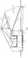
- Figure 1 diagrammatically shows a section of a first embodiment of a device according to the invention.
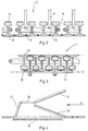
- Figure 2 diagrammatically shows the construction of an upper guiding surface of a plurality of rails arranged side by side.
- Figure 3 diagrammatically shows the construction of a lower guiding surface built up of rails.
- Figure 4 diagrammatically shows a section of a second embodiment of a device according to the invention.
- the device shown in Figure 1 comprises a first guiding surface 1 and a guiding surface 2 disposed thereabove.
- the guiding surface 1 slopes upwards from the left towards the right, when seen in Figure 1, at an angle of ⁇ 20° to the horizontal, whilst the guiding surface 2 slopes downwards from the right towards the left, when seen in Figure 1, likewise at an angle of ⁇ 20° to the horizontal.
- the guiding surface 1 is supported by a foundation beam 3 and at its left-hand end by columns 5 disposed on a foundation beam 4.
- the upper guiding surface 2 is suspended, by means of a truss 6, from a covering 7 housing the device.
- a trough 11 e.g. made of concrete
- a trough 12 e.g. made of concrete
- a further guiding surface 13 joins the end of the guiding surface 9 remote from the guiding surface 2, said guiding surface 13 sloping downwards from the guiding surface 9, thereby including an angle of ⁇ 20° with the horizontal.
- the end of the guiding surface 13 is disposed at some distance from the most left-hand wall of the trough 11, when seen in Figure 1.
- the guiding surfaces are preferably built up of rails located side by side.
- the upper guiding surface 2 is thereby built up of rails 14 disposed side by side, said rails extending from the right towards the left, parallel to the plane of drawing, when seen in Figure 1.
- the rails are subdivided into groups of interconnected rails located side by side, so that such groups of rails can be easily exchanged, if desired.
- such a group consists of four rails extending parallel to each other, which are interconnected by means of bolts 15 extending perpendicularly to the rails.
- the bolts 15 are surrounded by sleeves 16, to which arms 17 are secured for suspending the upper guiding surface.
- the flanges 18 of the rails thereby form the actual guiding surface located opposite the guiding surface 1.
- the slits between the abutting ends of the flanges 18 of the rails may be closed by means of bars 19 provided near said slits, which are welded to only one of the respective flanges.
- the guiding surfaces 8, 9 and 13 may be built up of rails in a similar manner.
- the abutting flanges 22 of the rails 20 will thereby form the actual guiding surface co-operating with the projectiles.
- Said flanges 22 are furthermore supported in an effective manner, in points spaced from the webs of the rails, by the heads of the rails 21.
- a solid, heavy construction of the lower guiding surface is obtained, which, as a result of the double arrangement of the rails, will be practically impenetrable to bullets or the like projectiles, whilst as a result of the heavy construction it will also be prevented that undesirable noise effects are produced.
- the trough 11 will be filled with water or a similar liquid.
- Bullets or the like projectiles are fired at the device in the direction indicated by the arrow A and generally caught by the lower guiding surface 1 or possibly by the upper guiding surface 2 thereby. It has become apparent that as a result of the selected inclination at which the two guiding surfaces extend, undesirable damage to the two guiding surfaces can at least substantially be avoided.
- the bullets or bullet rests caught move on through the small passage between the guiding surfaces 8 and 9, after which they are deflected by the guiding surface 13 and land into the liquid present in the trough 11, where they are decelerated by said liquid.
- a partition 11' in the trough 11 may be provided with holes, so that said partition acts as a wash plate, so as to prevent undesirable oscillation of the liquid. It is also possible to use an entirely closed partition 11' and to use the space to the right of said partition for catching water splashing over, which may then be pumped back, by means of a pump not shown, into the space located to the left of the partition 11', when seen in Figure 1.
- the trough 12 is provided to catch any water splashing from the trough 11.
- the metal parts caught in the water can be removed in a simple manner by means of screening techniques or the like.
- a relatively small amount of waste material is obtained hereby, which, in the form of scrap metal, lends itself very well for further environmentally sound removal casu quo processing.
- Figure 4 shows a somewhat simpler embodiment of a device for catching bullets according to the invention.
- This device is provided with two guiding surfaces 23 and 24 corresponding to the guiding surfaces 1 and 2 of the above-described device.
- a horizontally extending guiding surface 25 abuts the upper guiding surface 24.
- a further guiding surface 27 is disposed between the end of the guiding surface 25 remote from the guiding surface 24 and a sandbox disposed thereunder.
Landscapes
- Engineering & Computer Science (AREA)
- General Engineering & Computer Science (AREA)
- Aiming, Guidance, Guns With A Light Source, Armor, Camouflage, And Targets (AREA)
- Transition And Organic Metals Composition Catalysts For Addition Polymerization (AREA)
Applications Claiming Priority (2)
| Application Number | Priority Date | Filing Date | Title |
|---|---|---|---|
| NL9101229 | 1991-07-12 | ||
| NL9101229A NL9101229A (nl) | 1991-07-12 | 1991-07-12 | Inrichting voor het opvangen van kogels. |
Publications (2)
| Publication Number | Publication Date |
|---|---|
| EP0523801A1 true EP0523801A1 (fr) | 1993-01-20 |
| EP0523801B1 EP0523801B1 (fr) | 1996-06-19 |
Family
ID=19859511
Family Applications (1)
| Application Number | Title | Priority Date | Filing Date |
|---|---|---|---|
| EP92202116A Expired - Lifetime EP0523801B1 (fr) | 1991-07-12 | 1992-07-10 | Collecteur de balles |
Country Status (4)
| Country | Link |
|---|---|
| EP (1) | EP0523801B1 (fr) |
| AT (1) | ATE139620T1 (fr) |
| DE (1) | DE69211622D1 (fr) |
| NL (1) | NL9101229A (fr) |
Cited By (5)
| Publication number | Priority date | Publication date | Assignee | Title |
|---|---|---|---|---|
| AT494U1 (de) * | 1995-01-26 | 1995-11-27 | Riener Karl Stefan | Kugelfang fuer projektile |
| US5535662A (en) * | 1994-03-01 | 1996-07-16 | Bateman; Kyle E. | Bullet stop and containment chamber |
| US5811718A (en) * | 1994-03-01 | 1998-09-22 | Bateman; Kyle E. | Bullet stop and containment chamber with airborne contaminant removal |
| US9759531B2 (en) | 2001-12-12 | 2017-09-12 | Action Target Inc. | Bullet trap |
| US10371489B2 (en) | 2016-01-15 | 2019-08-06 | Action Target Inc. | Bullet deceleration tray damping mechanism |
Families Citing this family (3)
| Publication number | Priority date | Publication date | Assignee | Title |
|---|---|---|---|---|
| US7194944B2 (en) | 2001-12-12 | 2007-03-27 | Action Target, Inc. | Bullet trap |
| US8469364B2 (en) | 2006-05-08 | 2013-06-25 | Action Target Inc. | Movable bullet trap |
| US8827273B2 (en) | 2010-08-02 | 2014-09-09 | Action Target Inc. | Clearing trap |
Citations (6)
| Publication number | Priority date | Publication date | Assignee | Title |
|---|---|---|---|---|
| DE316195C (fr) * | 1920-01-03 | |||
| US2420304A (en) * | 1944-05-05 | 1947-05-13 | Donald T Diem | Spent bullet trap |
| US2772092A (en) * | 1954-02-17 | 1956-11-27 | Nikoden Joseph | Bullet traps |
| FR1288152A (fr) * | 1961-02-08 | 1962-03-24 | R L Lobert Freres Sa | Boîte métallique portative à mire perpétuelle et récupération des déchets pour tir de précision à courte distance sans danger |
| BE681425A (fr) * | 1965-06-05 | 1966-10-31 | ||
| US3701532A (en) * | 1970-10-07 | 1972-10-31 | Detroit Bullet Trap Corp | Bullet deflection apparatus |
-
1991
- 1991-07-12 NL NL9101229A patent/NL9101229A/nl unknown
-
1992
- 1992-07-10 DE DE69211622T patent/DE69211622D1/de not_active Expired - Lifetime
- 1992-07-10 AT AT92202116T patent/ATE139620T1/de not_active IP Right Cessation
- 1992-07-10 EP EP92202116A patent/EP0523801B1/fr not_active Expired - Lifetime
Patent Citations (6)
| Publication number | Priority date | Publication date | Assignee | Title |
|---|---|---|---|---|
| DE316195C (fr) * | 1920-01-03 | |||
| US2420304A (en) * | 1944-05-05 | 1947-05-13 | Donald T Diem | Spent bullet trap |
| US2772092A (en) * | 1954-02-17 | 1956-11-27 | Nikoden Joseph | Bullet traps |
| FR1288152A (fr) * | 1961-02-08 | 1962-03-24 | R L Lobert Freres Sa | Boîte métallique portative à mire perpétuelle et récupération des déchets pour tir de précision à courte distance sans danger |
| BE681425A (fr) * | 1965-06-05 | 1966-10-31 | ||
| US3701532A (en) * | 1970-10-07 | 1972-10-31 | Detroit Bullet Trap Corp | Bullet deflection apparatus |
Cited By (6)
| Publication number | Priority date | Publication date | Assignee | Title |
|---|---|---|---|---|
| US5535662A (en) * | 1994-03-01 | 1996-07-16 | Bateman; Kyle E. | Bullet stop and containment chamber |
| US5811718A (en) * | 1994-03-01 | 1998-09-22 | Bateman; Kyle E. | Bullet stop and containment chamber with airborne contaminant removal |
| AT494U1 (de) * | 1995-01-26 | 1995-11-27 | Riener Karl Stefan | Kugelfang fuer projektile |
| US9759531B2 (en) | 2001-12-12 | 2017-09-12 | Action Target Inc. | Bullet trap |
| US10088283B2 (en) | 2001-12-12 | 2018-10-02 | Action Target Inc. | Bullet trap |
| US10371489B2 (en) | 2016-01-15 | 2019-08-06 | Action Target Inc. | Bullet deceleration tray damping mechanism |
Also Published As
| Publication number | Publication date |
|---|---|
| EP0523801B1 (fr) | 1996-06-19 |
| NL9101229A (nl) | 1993-02-01 |
| DE69211622D1 (de) | 1996-07-25 |
| ATE139620T1 (de) | 1996-07-15 |
Similar Documents
| Publication | Publication Date | Title |
|---|---|---|
| US5121671A (en) | Bullet trap | |
| US5400692A (en) | Bullet stop and containment chamber | |
| EP0729561B1 (fr) | Piege a balles | |
| EP0523801B1 (fr) | Collecteur de balles | |
| US5456155A (en) | Bullet trap assembly | |
| TW208740B (fr) | ||
| US5718434A (en) | Bullet trap | |
| US3404887A (en) | Bullet trap with upwardly inclined impact plates | |
| US3447806A (en) | Bullet trapping assembly | |
| US5441280A (en) | Contaminant recovery system for a rifle range | |
| Griffith | Fortifications of the Western Front 1914–18 | |
| KR102077968B1 (ko) | 사격장 피탄 방호설비 | |
| JP4515876B2 (ja) | 弾丸捕集装置 | |
| AU645163B2 (en) | Bullet trap | |
| KR20190140718A (ko) | 탄두 회수장치 | |
| DE2013726B1 (de) | Hafenbeckeneinfassung | |
| RU98119829A (ru) | Композитная сталежелезобетонная буровая платформа гравитационного типа | |
| ITBS20110058A1 (it) | Poligono di tiro | |
| DE19613723C1 (de) | Umhauste Anlage für das sportliche und/oder jagdliche und/oder behördliche Schießen mit Schußwaffen | |
| KR101658565B1 (ko) | 비활성탄 회수시설 및 발사진지 | |
| DD201047A1 (de) | Schiessstand,vorzugsweise fuer kleinkaliberfeuerwaffen | |
| DD200583A1 (de) | Schiessstand,vorzugsweise fuer kleinkaliberpistole | |
| Smith | Trench warfare: A manual for officers and Men | |
| JP2006317014A (ja) | 射撃場の構造 | |
| DE102015006593B4 (de) | Schrotfangeinrichtung für eine Schießanlage |
Legal Events
| Date | Code | Title | Description |
|---|---|---|---|
| PUAI | Public reference made under article 153(3) epc to a published international application that has entered the european phase |
Free format text: ORIGINAL CODE: 0009012 |
|
| AK | Designated contracting states |
Kind code of ref document: A1 Designated state(s): AT BE CH DE DK ES FR GB GR IT LI LU MC NL PT SE |
|
| 17P | Request for examination filed |
Effective date: 19930713 |
|
| 17Q | First examination report despatched |
Effective date: 19941014 |
|
| GRAH | Despatch of communication of intention to grant a patent |
Free format text: ORIGINAL CODE: EPIDOS IGRA |
|
| GRAH | Despatch of communication of intention to grant a patent |
Free format text: ORIGINAL CODE: EPIDOS IGRA |
|
| GRAA | (expected) grant |
Free format text: ORIGINAL CODE: 0009210 |
|
| AK | Designated contracting states |
Kind code of ref document: B1 Designated state(s): AT BE CH DE DK ES FR GB GR IT LI LU MC NL PT SE |
|
| PG25 | Lapsed in a contracting state [announced via postgrant information from national office to epo] |
Ref country code: IT Free format text: LAPSE BECAUSE OF FAILURE TO SUBMIT A TRANSLATION OF THE DESCRIPTION OR TO PAY THE FEE WITHIN THE PRESCRIBED TIME-LIMIT;WARNING: LAPSES OF ITALIAN PATENTS WITH EFFECTIVE DATE BEFORE 2007 MAY HAVE OCCURRED AT ANY TIME BEFORE 2007. THE CORRECT EFFECTIVE DATE MAY BE DIFFERENT FROM THE ONE RECORDED. Effective date: 19960619 Ref country code: DK Effective date: 19960619 Ref country code: FR Effective date: 19960619 Ref country code: BE Effective date: 19960619 Ref country code: AT Effective date: 19960619 Ref country code: CH Free format text: LAPSE BECAUSE OF FAILURE TO SUBMIT A TRANSLATION OF THE DESCRIPTION OR TO PAY THE FEE WITHIN THE PRESCRIBED TIME-LIMIT Effective date: 19960619 Ref country code: LI Free format text: LAPSE BECAUSE OF FAILURE TO SUBMIT A TRANSLATION OF THE DESCRIPTION OR TO PAY THE FEE WITHIN THE PRESCRIBED TIME-LIMIT Effective date: 19960619 Ref country code: ES Free format text: THE PATENT HAS BEEN ANNULLED BY A DECISION OF A NATIONAL AUTHORITY Effective date: 19960619 Ref country code: GR Free format text: LAPSE BECAUSE OF FAILURE TO SUBMIT A TRANSLATION OF THE DESCRIPTION OR TO PAY THE FEE WITHIN THE PRESCRIBED TIME-LIMIT Effective date: 19960619 |
|
| REF | Corresponds to: |
Ref document number: 139620 Country of ref document: AT Date of ref document: 19960715 Kind code of ref document: T |
|
| REF | Corresponds to: |
Ref document number: 69211622 Country of ref document: DE Date of ref document: 19960725 |
|
| PG25 | Lapsed in a contracting state [announced via postgrant information from national office to epo] |
Ref country code: LU Free format text: LAPSE BECAUSE OF NON-PAYMENT OF DUE FEES Effective date: 19960731 |
|
| PG25 | Lapsed in a contracting state [announced via postgrant information from national office to epo] |
Ref country code: SE Effective date: 19960919 Ref country code: PT Effective date: 19960919 Ref country code: GB Effective date: 19960919 |
|
| PG25 | Lapsed in a contracting state [announced via postgrant information from national office to epo] |
Ref country code: DE Effective date: 19960920 |
|
| EN | Fr: translation not filed | ||
| REG | Reference to a national code |
Ref country code: CH Ref legal event code: PL |
|
| PG25 | Lapsed in a contracting state [announced via postgrant information from national office to epo] |
Ref country code: MC Effective date: 19970131 |
|
| PLBE | No opposition filed within time limit |
Free format text: ORIGINAL CODE: 0009261 |
|
| GBPC | Gb: european patent ceased through non-payment of renewal fee |
Effective date: 19960919 |
|
| 26N | No opposition filed | ||
| PGFP | Annual fee paid to national office [announced via postgrant information from national office to epo] |
Ref country code: NL Payment date: 19970730 Year of fee payment: 6 |
|
| PG25 | Lapsed in a contracting state [announced via postgrant information from national office to epo] |
Ref country code: NL Free format text: LAPSE BECAUSE OF NON-PAYMENT OF DUE FEES Effective date: 19990201 |
|
| NLV4 | Nl: lapsed or anulled due to non-payment of the annual fee |
Effective date: 19990201 |