EP0523859B1 - Moteur à combustion interne turbocompressé - Google Patents
Moteur à combustion interne turbocompressé Download PDFInfo
- Publication number
- EP0523859B1 EP0523859B1 EP92305716A EP92305716A EP0523859B1 EP 0523859 B1 EP0523859 B1 EP 0523859B1 EP 92305716 A EP92305716 A EP 92305716A EP 92305716 A EP92305716 A EP 92305716A EP 0523859 B1 EP0523859 B1 EP 0523859B1
- Authority
- EP
- European Patent Office
- Prior art keywords
- pressure
- engine
- port
- valve
- wastegate
- Prior art date
- Legal status (The legal status is an assumption and is not a legal conclusion. Google has not performed a legal analysis and makes no representation as to the accuracy of the status listed.)
- Expired - Lifetime
Links
- 238000002485 combustion reaction Methods 0.000 title claims description 21
- 239000000446 fuel Substances 0.000 claims description 35
- 230000001105 regulatory effect Effects 0.000 claims description 6
- 238000011144 upstream manufacturing Methods 0.000 claims description 3
- 230000001276 controlling effect Effects 0.000 claims 1
- 239000007789 gas Substances 0.000 description 14
- 230000002411 adverse Effects 0.000 description 1
- 230000000903 blocking effect Effects 0.000 description 1
- 238000010276 construction Methods 0.000 description 1
- 230000001419 dependent effect Effects 0.000 description 1
- 230000003292 diminished effect Effects 0.000 description 1
- 238000002347 injection Methods 0.000 description 1
- 239000007924 injection Substances 0.000 description 1
- 230000007257 malfunction Effects 0.000 description 1
- 238000012986 modification Methods 0.000 description 1
- 230000004048 modification Effects 0.000 description 1
- 230000003449 preventive effect Effects 0.000 description 1
- 230000000750 progressive effect Effects 0.000 description 1
- 238000000926 separation method Methods 0.000 description 1
- 230000011664 signaling Effects 0.000 description 1
Images

Classifications
-
- F—MECHANICAL ENGINEERING; LIGHTING; HEATING; WEAPONS; BLASTING
- F02—COMBUSTION ENGINES; HOT-GAS OR COMBUSTION-PRODUCT ENGINE PLANTS
- F02B—INTERNAL-COMBUSTION PISTON ENGINES; COMBUSTION ENGINES IN GENERAL
- F02B37/00—Engines characterised by provision of pumps driven at least for part of the time by exhaust
- F02B37/12—Control of the pumps
- F02B37/18—Control of the pumps by bypassing exhaust from the inlet to the outlet of turbine or to the atmosphere
- F02B37/183—Arrangements of bypass valves or actuators therefor
- F02B37/186—Arrangements of actuators or linkage for bypass valves
-
- Y—GENERAL TAGGING OF NEW TECHNOLOGICAL DEVELOPMENTS; GENERAL TAGGING OF CROSS-SECTIONAL TECHNOLOGIES SPANNING OVER SEVERAL SECTIONS OF THE IPC; TECHNICAL SUBJECTS COVERED BY FORMER USPC CROSS-REFERENCE ART COLLECTIONS [XRACs] AND DIGESTS
- Y02—TECHNOLOGIES OR APPLICATIONS FOR MITIGATION OR ADAPTATION AGAINST CLIMATE CHANGE
- Y02T—CLIMATE CHANGE MITIGATION TECHNOLOGIES RELATED TO TRANSPORTATION
- Y02T10/00—Road transport of goods or passengers
- Y02T10/10—Internal combustion engine [ICE] based vehicles
- Y02T10/12—Improving ICE efficiencies
Definitions
- This invention relates to an exhaust gas turbocharger for an internal combustion engine having an exhaust port and an intake port, in combination with pressure responsive fuel feed means for supplying fuel to combustion chambers of the engine, the turbocharger, which is known as a wastegate type turbocharger, comprising a turbine section provided with a housing having a primary passageway therethrough for connection to the exhaust port of the engine;
- GB-A-2079364 discloses a distribution fuel injection pump for use with a diesel engine fitted with a wastegate type turbocharger, the pump being arranged so that fuel supply is dependent upon the pressure of the compressed air.
- an exhaust gas turbocharger for an internal combustion engine and an engine fuel pump for supplying fuel to the combustion chambers of the engine as claimed-by claim 1.
- This invention also relates in another aspect to an internal combustion engine including such a combination of an exhaust gas turbocharger and pressure responsive fuel feed means as claimed by claim 5.
- any failure due to leakage in either the wastegate boost sensing line or diaphragm causes a reduction in the fuel flow to the engine cylinders.
- Such reduced fuel flow adversely affects the power output of the engine thereby providing incentive to operating personnel to remedy the wastegate problem before any progressive serious engine damage occurs.
- a turbocharged internal combustion engine which utilizes a pressure responsive wastegate unit having an adjustable valve for regulating the exhaust gas flow to the turbine section of the turbocharger.
- the unit is in pressure communication with a port leading to an interior cavity formed in a multiport connection.
- a second port to the connection cavity is in pressure communication with the engine intake manifold.
- a third port to the cavity is in pressure communication with a fuel feed means for the engine.
- the wastegate unit adjustable valve is biased to assume a close position blocking bypass flow of the exhaust gas around the turbine section of the turbocharger. The bias pressure on the unit adjustable valve is in opposition to the pressure maintained within the connection cavity.
- the adjustable valve when the pressure within the cavity is below the bias pressure, the adjustable valve will assume the close position causing the pressure imposed on the fuel feed means through the third port to be reduced resulting in the fuel fed to the engine cylinders to be reduced preventing overspeeding of the turbocharger rotors (e.g., turbine and compressor wheels).
- the turbocharger rotors e.g., turbine and compressor wheels
- Fig. 1 is a schematic representation of one embodiment of the improved turbocharged internal combustion engine.
- Fig. 2 is an enlarged schematic representation of the wastegate unit per se incorporated in the engine of Fig. 1.
- Fig. 3 is an elevational view of the multiport connection per se incorporated in the engine of Fig. 1 with a portion of the connection removed so as to expose the interior cavity formed therein.
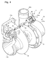
- Fig. 4 is an enlarged fragmentary perspective view of the turbocharger of Fig. 1 shown with the wastegate unit mounted thereon; segments of the unit and turbocharger being removed so as to expose interior portions thereof.
- a turbocharged internal combustion engine 10 which utilizes a wastegate unit 11 in combination with a turbocharger 12, sometimes referred to as a wastegate type.
- the engine 10 includes a cylinder block and head combination 13 of conventional design; an air intake manifold 14 in communication with engine combustion chambers, not shown, formed in the cylinder head; and a fuel feed means (pump) 15 also in communication with the combustion chambers.
- the pump 15 is provided with a pressure sensitive control 15a which regulates the fuel flow from the pump to the combustion chambers.
- Each combustion chamber may be of conventional design and includes intake and exhaust valves which open and close in a timed sequence with the stroke of a corresponding piston.
- the exhaust gases generated in each combustion chamber and corresponding cylinder flow into an exhaust manifold, not shown. From the exhaust manifold the exhaust gases are directed to an intake side 17a of a housing 17 forming a component of the turbocharger turbine section 18, see Fig. 4. From the intake side 17a, the exhaust gases flow through an interior primary passageway 17e to a turbine wheel (rotor) not shown, which is rotatably mounted within the housing 17. From the turbine wheel the exhaust gases exit through a discharge side 17b of the housing. As seen in Fig.
- housing 17 is provided with a bypass, or secondary, passageway 17c which is upstream of the turbine wheel and communicates at one end through port 17d with the primary passageway 17e and at the opposite end through a port 17f with the discharge side 17b, see Fig. 2.
- a bypass, or secondary, passageway 17c which is upstream of the turbine wheel and communicates at one end through port 17d with the primary passageway 17e and at the opposite end through a port 17f with the discharge side 17b, see Fig. 2.
- a bypass, or secondary, passageway 17c which is upstream of the turbine wheel and communicates at one end through port 17d with the primary passageway 17e and at the opposite end through a port 17f with the discharge side 17b, see Fig. 2.
- turbocharger 12 includes a compressor section 20 having a housing 21 in which is disposed a compressor wheel (rotor), not shown.
- the turbine section housing 17 and the compressor section housing 21 are interconnected by a sleeve 22 through which extends a shaft, not shown, keyed to the turbine and compressor wheels.
- Housing 21 is provided with an air intake side 21a and a discharge side 21b, the latter being connected via passageway 23 to the engine intake manifold 14, see Fig. 1.
- an air/air aftercooler may be disposed within passageway 23 between the turbocharger 12 and the intake manifold 14.
- the wastegate unit 11 includes a casing 24 in which is mounted a diaphragm D effecting separation of the casing interior into a pair of contiguous chambers 24a, 24b.
- a diaphragm D Secured to the face of diaphragm D, which is adjacent chamber 24b, is one end 25a of a rod 25.
- the rod 25 slidably extends through an opening 26 formed in the exterior wall of casing 24.
- a bias spring 27 Disposed within housing chamber 24b between the diaphragm D and opening 26 is a bias spring 27.
- the opposite end 25b of the rod is pivotably connected to a linkage assembly 28 which is connected to valve V, see Fig. 2.
- the rod 25 is formed of two sections I and II which are interconnected in endwise relation by an internally threaded sleeve 30.
- Casing 24 is provided with a port 31 which communicates with interior chamber 24a.
- Port 31 is connected by tubing 32, sometimes referred to as the boost sensing line, to a multiport connection 33.
- connection 33 has a first port 34 connected to tubing 32; a second port 35 connected by tubing 36 to the engine intake manifold 14; and a third port 37 connected to the pressure sensitive control unit 15a forming a component of the fuel pump 15.
- the control unit 15a is a conventional design. All of the ports 34, 35 and 37 communicate with an interior cavity 38 formed in the connection 33, see Fig. 3.
- the pressure within the air intake manifold 14 is reflected in cavity 38 which, in turn, determines the pressure within chamber 24a and the setting of the wastegate unit valve V.
- the pressure within connection cavity 38 is also transmitted to the pump control unit 15a which regulates the rate of flow of the fuel from the fuel pump.
- an orifice 40 of a predetermined size is mounted on port 35 of the connection 33, see Fig. 3.
- the orifice enables the control unit 15a of the fuel pump to be more responsive to the pressure drop within unit chamber 24a.
- a turbocharger internal combustion engine having a wastegate unit of simple construction which is mounted in such a way as to directly affect the output of the engine fuel pump and prevent overspeeding of the turbocharger when there is a leak in certain components of the unit.
Landscapes
- Engineering & Computer Science (AREA)
- Chemical & Material Sciences (AREA)
- Combustion & Propulsion (AREA)
- Mechanical Engineering (AREA)
- General Engineering & Computer Science (AREA)
- Supercharger (AREA)
- Output Control And Ontrol Of Special Type Engine (AREA)
- Combined Controls Of Internal Combustion Engines (AREA)
Claims (5)
- L'ensemble combiné d'un turbocompresseur de gaz d'échappement (12) et d'une pompe à carburant de moteur (15) pour un moteur à combustion interne (10) qui a un port d'échappement et un port d'admission d'air, la pompe à carburant (15) étant pourvue de moyens de commande sensibles à la pression (15a) pour régler l'écoulement de carburant à partir de la pompe à carburant (15) jusqu'au moteur (10) et commandant de ce fait la vitesse de fonctionnement du moteur (10), le turbocompresseur de gaz d'échappement (12) comprenant une section de turbine (18) pourvue d'un boîtier (17) ayant un passage primaire (17e) dans lequel est montée une roue de turbine, un passage secondaire de bipasse (17c) communiquant avec ledit passage primaire (17e) en amont de ladite roue de turbine, et une section de compresseur (20) pourvue d'une roue de compresseur activement reliée à ladite roue de turbine et ayant un côté de décharge (21b) pour une connexion à un collecteur d'admission d'air (14) du moteur (10) par l'intermédiaire dudit port d'admission d'air;
des moyens de dégagement (11) comprenant une soupape sensible à la pression (V) pour régler l'écoulement de gaz d'échappement à travers le passage secondaire (17c), ladite soupape (V) étant poussée pour prendre une position fermée par rapport audit passage secondaire (17c); et des moyens de connexion (33) avec un premier port (34) en communication de pression avec lesdits moyens de dégagement (11), la pression à l'intérieur des moyens de connexion (33) étant ainsi en opposition à la poussée dans la soupape, un deuxième port (35) apte à être en communication de pression avec le collecteur d'admission d'air (14) du moteur et un troisième port (37) qui est en communication de pression avec lesdits moyens de commande sensibles à la pression (15a), dans lequel ladite soupape (V) est conçue pour s'ouvrir et permettre au gaz d'échappement de bipasser ladite roue de turbine lorsque la pression à l'intérieur desdits moyens de connexion (33) excède une pression prédéterminée et une réduction dans l'écoulement de carburant vers le moteur (10) est provoquée dans le cas d'une montée excessive de la pression du cylindre due à un surrégime des rotors du turbocompresseur suite à la fermeture de ladite soupape (V) à cause d'une défaillance, ladite soupape (V) étant dès lors fermée à cause d'une fuite dans la communication de pression dudit deuxième port (35) avec lesdits moyens de dégagement (11) qui entraîne une réduction de la pression à l'intérieur desdits moyens de connexion (33), cette réduction de pression est appliquée auxdits moyens d'alimentation en carburant par l'intermédiaire de ladite communication de pression de façon à entraîner la réduction de l'écoulement de carburant vers le moteur (10), caractérisé en ce que lesdits moyens de connexion ont une cavité intérieure (38) ayant un volume agrandi, la pression à l'intérieur du collecteur d'admission d'air (14) étant dès lors répercutée dans ladite cavité (38) de volume agrandi qui, à son tour, détermine le réglage de la soupape de dégagement (V). - L'ensemble combiné d'un turbocompresseur de gaz d'échappement et d'une pompe à carburant de moteur pour un moteur à combustion interne tel que revendiqué dans la revendication 1, dans lequel ledit deuxième port (35) de ladite connexion à ports multiples (33) est pourvu d'un orifice de limitation de pression (40), lesdits moyens d'alimentation en carburant (15) étant dès lors plus sensibles à une chute de pression à l'intérieur dudit premier port (34).
- L'ensemble combiné d'un turbocompresseur de gaz d'échappement (12) et d'une pompe à carburant de moteur (15) pour un moteur à combustion interne suivant la revendication 1 ou la revendication 2, dans lequel lesdits moyens de dégagement (11) comprennent un boîtier (24) avec un intérieur ayant un diaphragme (D) monté dans celui-ci séparant ledit intérieur en une paire de chambres continues (24a et 24b), un côté dudit diaphragme (D) étant en communication de pression avec ledit deuxième port (37) et l'autre côté dudit diaphragme (D) étant relié activement à ladite soupape (V).
- L'ensemble combiné d'un turbocompresseur de gaz d'échappement (12) et d'une pompe à carburant de moteur (15) pour un moteur à combustion interne suivant la revendication 3, dans lequel lesdits moyens de dégagement (11) sont activement reliés à ladite soupape (V) par un poussoir (25) ayant une certaine longueur; des moyens (I, II et 30) étant prévus pour régler la poussée sur ladite soupape (V) de façon à modifier ladite pression prédéterminée, comprenant des moyens (30) pour changer ladite longueur dudit poussoir (25).
- Un moteur à combustion interne (10) ayant un ensemble combiné suivant l'une quelconque des revendications 1 à 4.
Applications Claiming Priority (2)
| Application Number | Priority Date | Filing Date | Title |
|---|---|---|---|
| US07/730,218 US5159815A (en) | 1991-07-15 | 1991-07-15 | Turbocharged internal combustion engine |
| US730218 | 2000-12-05 |
Publications (2)
| Publication Number | Publication Date |
|---|---|
| EP0523859A1 EP0523859A1 (fr) | 1993-01-20 |
| EP0523859B1 true EP0523859B1 (fr) | 1996-08-14 |
Family
ID=24934442
Family Applications (1)
| Application Number | Title | Priority Date | Filing Date |
|---|---|---|---|
| EP92305716A Expired - Lifetime EP0523859B1 (fr) | 1991-07-15 | 1992-06-22 | Moteur à combustion interne turbocompressé |
Country Status (4)
| Country | Link |
|---|---|
| US (1) | US5159815A (fr) |
| EP (1) | EP0523859B1 (fr) |
| JP (1) | JP2837995B2 (fr) |
| DE (1) | DE69212738T2 (fr) |
Families Citing this family (16)
| Publication number | Priority date | Publication date | Assignee | Title |
|---|---|---|---|---|
| FR2707712A1 (fr) * | 1993-07-12 | 1995-01-20 | Mugnier Henri Sa | Dispositif permettant de relier, de façon rigide, un pressostat à une soupape d'échappement de gaz, notamment pour les turbos compresseurs de moteurs à combustion. |
| US5447031A (en) * | 1994-04-20 | 1995-09-05 | Caterpillar Inc. | Wastegate failure detection apparatus and method for operating same |
| GB9816275D0 (en) * | 1998-07-27 | 1998-09-23 | Holset Engineering Co | Turbocharger with wastegate |
| US6155050A (en) * | 1999-06-01 | 2000-12-05 | Cummins Engine Co Inc | System and method for protecting a turbocharger in the event of a wastegate failure |
| US6539715B2 (en) * | 2000-12-18 | 2003-04-01 | Caterpillar Inc | Turbocharger swivel connector |
| FR2823795B1 (fr) | 2001-04-18 | 2003-08-08 | Emt 74 | Dispositif pour relier la tige d'un pressostat a une soupape de decharge d'un turbocompresseur, turbocompresseur et moteur a combustion interne ainsi equipes |
| GB0111681D0 (en) | 2001-05-11 | 2001-07-04 | Holset Engineering Co | Turbo charger with waste gate |
| DE102007055630A1 (de) * | 2007-11-21 | 2009-05-28 | Bosch Mahle Turbo Systems Gmbh & Co. Kg | Ladeeinrichtung |
| DE102008032930A1 (de) * | 2008-07-12 | 2010-01-14 | Bosch Mahle Turbo Systems Gmbh & Co. Kg | Abgasturbolader für ein Kraftfahrzeug |
| EP2473724B1 (fr) * | 2009-09-03 | 2014-04-23 | Volkswagen Aktiengesellschaft | Dispositif by-pass pour turbo compresseur |
| IT1396413B1 (it) * | 2009-10-30 | 2012-11-19 | Natali | Metodo per la taratura di attuatori pneumatici ed attuatore tarato cosi' ottenibile. |
| DE102011111471A1 (de) | 2011-08-23 | 2013-02-28 | GM Global Technology Operations LLC (n. d. Gesetzen des Staates Delaware) | Abgasanlage eines Verbrennungsmotors mit Einrichtung zur Wärmerückgewinnung, sowie Verfahren zum Betreiben derselben |
| DE102013202191A1 (de) * | 2013-02-11 | 2014-08-14 | Continental Automotive Gmbh | Abgasturbolader mit einer Regeleinheit |
| WO2015013061A1 (fr) * | 2013-07-22 | 2015-01-29 | Borgwarner Inc. | Turbocompresseur à gaz d'échappement |
| US10107184B2 (en) * | 2016-09-06 | 2018-10-23 | Ford Global Technologies, Llc | Method and system for wastegate control |
| USD1072872S1 (en) * | 2020-07-27 | 2025-04-29 | Transportation Ip Holdings Llc | Coolant apparatus |
Family Cites Families (10)
| Publication number | Priority date | Publication date | Assignee | Title |
|---|---|---|---|---|
| SU781382A1 (ru) * | 1979-02-07 | 1980-11-23 | Военная Ордена Ленина Академия Тыла И Транспорта | Двигатель внутреннего сгорани |
| JPS6041213B2 (ja) * | 1979-09-12 | 1985-09-14 | トヨタ自動車株式会社 | タ−ボチヤ−ジ内燃機関の破壊防止装置 |
| JPS614673Y2 (fr) * | 1979-12-29 | 1986-02-13 | ||
| JPS56163631U (fr) * | 1980-05-06 | 1981-12-04 | ||
| JPS5780624U (fr) * | 1980-11-05 | 1982-05-18 | ||
| JPS6234742Y2 (fr) * | 1981-05-09 | 1987-09-04 | ||
| JPS58124622U (ja) * | 1982-02-19 | 1983-08-24 | 三菱電機株式会社 | 過給圧制御装置 |
| DE3307265A1 (de) * | 1983-03-02 | 1984-09-06 | Volkswagenwerk Ag, 3180 Wolfsburg | Regeleinrichtung fuer einspritzpumpen |
| US4656834A (en) * | 1985-12-24 | 1987-04-14 | The Garrett Corporation | Electronic turbocharger control |
| JPS6368722A (ja) * | 1986-09-10 | 1988-03-28 | Hitachi Ltd | ウエストゲ−ト弁の制御装置 |
-
1991
- 1991-07-15 US US07/730,218 patent/US5159815A/en not_active Expired - Fee Related
-
1992
- 1992-06-22 DE DE69212738T patent/DE69212738T2/de not_active Expired - Fee Related
- 1992-06-22 EP EP92305716A patent/EP0523859B1/fr not_active Expired - Lifetime
- 1992-07-07 JP JP4180057A patent/JP2837995B2/ja not_active Expired - Fee Related
Also Published As
| Publication number | Publication date |
|---|---|
| DE69212738T2 (de) | 1996-12-05 |
| DE69212738D1 (de) | 1996-09-19 |
| JP2837995B2 (ja) | 1998-12-16 |
| JPH05209532A (ja) | 1993-08-20 |
| US5159815A (en) | 1992-11-03 |
| EP0523859A1 (fr) | 1993-01-20 |
Similar Documents
| Publication | Publication Date | Title |
|---|---|---|
| EP0523859B1 (fr) | Moteur à combustion interne turbocompressé | |
| US4709552A (en) | Multiple cylinder internal combustion engine with exhaust turbochargers | |
| US9903267B2 (en) | Multi-stage turbocharger system | |
| US4138849A (en) | Exhaust braking valve | |
| EP1486678B1 (fr) | Compresseur avec deuxième canal de refoulement d' air | |
| US4224794A (en) | Turbine assembly | |
| US6564554B2 (en) | Method and apparatus to control a turbocharger wastegate using exhaust pressure | |
| CA2380239A1 (fr) | Electrovalve a air comprime integralement montee pour commande de vanne de decharge | |
| US4080946A (en) | Internal combustion engine shut-down control valve | |
| US6109886A (en) | Compressed-air supply installation with reduced idling power | |
| US4169355A (en) | Turbocharger wastegate valve | |
| CA2025050C (fr) | Systeme de regulation d'huile de lubrification, pour moteur a piston rotatif | |
| US20040003597A1 (en) | Battle override valve | |
| JPH04203317A (ja) | ターボ過給式エンジンの排気制御装置 | |
| US4454718A (en) | Safety control system for a turbocharged engine | |
| EP0207671B1 (fr) | Turbocompresseur comprenant une turbine à section d'admission variable | |
| US6318084B1 (en) | Internal-combustion engine having an engine braking device | |
| SU1192634A3 (ru) | Двигатель внутреннего сгорани с наддувом | |
| EP0508508A1 (fr) | Dispositif d'alimentation en air pour un moteur | |
| JPS6030448Y2 (ja) | 内燃機関の空燃比調節装置 | |
| CA1082065A (fr) | Robinet d'arret monte sur le circuit d'alimentation d'un moteur a combustion interne | |
| JPH0121138Y2 (fr) | ||
| JPS6349547Y2 (fr) | ||
| KR19990020117A (ko) | 터보 차저의 웨이스트 게이트 | |
| JPS5948287B2 (ja) | 排気タ−ビン式過給装置の警報装置 |
Legal Events
| Date | Code | Title | Description |
|---|---|---|---|
| PUAI | Public reference made under article 153(3) epc to a published international application that has entered the european phase |
Free format text: ORIGINAL CODE: 0009012 |
|
| AK | Designated contracting states |
Kind code of ref document: A1 Designated state(s): DE GB |
|
| 17P | Request for examination filed |
Effective date: 19930625 |
|
| 17Q | First examination report despatched |
Effective date: 19940308 |
|
| GRAH | Despatch of communication of intention to grant a patent |
Free format text: ORIGINAL CODE: EPIDOS IGRA |
|
| GRAH | Despatch of communication of intention to grant a patent |
Free format text: ORIGINAL CODE: EPIDOS IGRA |
|
| GRAA | (expected) grant |
Free format text: ORIGINAL CODE: 0009210 |
|
| AK | Designated contracting states |
Kind code of ref document: B1 Designated state(s): DE GB |
|
| REF | Corresponds to: |
Ref document number: 69212738 Country of ref document: DE Date of ref document: 19960919 |
|
| PLBE | No opposition filed within time limit |
Free format text: ORIGINAL CODE: 0009261 |
|
| STAA | Information on the status of an ep patent application or granted ep patent |
Free format text: STATUS: NO OPPOSITION FILED WITHIN TIME LIMIT |
|
| 26N | No opposition filed | ||
| REG | Reference to a national code |
Ref country code: GB Ref legal event code: IF02 |
|
| PGFP | Annual fee paid to national office [announced via postgrant information from national office to epo] |
Ref country code: GB Payment date: 20030619 Year of fee payment: 12 |
|
| PGFP | Annual fee paid to national office [announced via postgrant information from national office to epo] |
Ref country code: DE Payment date: 20030630 Year of fee payment: 12 |
|
| PG25 | Lapsed in a contracting state [announced via postgrant information from national office to epo] |
Ref country code: GB Free format text: LAPSE BECAUSE OF NON-PAYMENT OF DUE FEES Effective date: 20040622 |
|
| PG25 | Lapsed in a contracting state [announced via postgrant information from national office to epo] |
Ref country code: DE Free format text: LAPSE BECAUSE OF NON-PAYMENT OF DUE FEES Effective date: 20050101 |
|
| GBPC | Gb: european patent ceased through non-payment of renewal fee |
Effective date: 20040622 |