EP0524555A2 - Mehrstufiger Gegenstrom-Hohlfasermembranmodul - Google Patents
Mehrstufiger Gegenstrom-Hohlfasermembranmodul Download PDFInfo
- Publication number
- EP0524555A2 EP0524555A2 EP92112280A EP92112280A EP0524555A2 EP 0524555 A2 EP0524555 A2 EP 0524555A2 EP 92112280 A EP92112280 A EP 92112280A EP 92112280 A EP92112280 A EP 92112280A EP 0524555 A2 EP0524555 A2 EP 0524555A2
- Authority
- EP
- European Patent Office
- Prior art keywords
- fibers
- bundle
- module
- permeate
- tubesheet
- Prior art date
- Legal status (The legal status is an assumption and is not a legal conclusion. Google has not performed a legal analysis and makes no representation as to the accuracy of the status listed.)
- Withdrawn
Links
Images


Classifications
-
- B—PERFORMING OPERATIONS; TRANSPORTING
- B01—PHYSICAL OR CHEMICAL PROCESSES OR APPARATUS IN GENERAL
- B01D—SEPARATION
- B01D61/00—Processes of separation using semi-permeable membranes, e.g. dialysis, osmosis or ultrafiltration; Apparatus, accessories or auxiliary operations specially adapted therefor
-
- B—PERFORMING OPERATIONS; TRANSPORTING
- B01—PHYSICAL OR CHEMICAL PROCESSES OR APPARATUS IN GENERAL
- B01D—SEPARATION
- B01D53/00—Separation of gases or vapours; Recovering vapours of volatile solvents from gases; Chemical or biological purification of waste gases, e.g. engine exhaust gases, smoke, fumes, flue gases, aerosols
- B01D53/22—Separation of gases or vapours; Recovering vapours of volatile solvents from gases; Chemical or biological purification of waste gases, e.g. engine exhaust gases, smoke, fumes, flue gases, aerosols by diffusion
-
- B—PERFORMING OPERATIONS; TRANSPORTING
- B01—PHYSICAL OR CHEMICAL PROCESSES OR APPARATUS IN GENERAL
- B01D—SEPARATION
- B01D63/00—Apparatus in general for separation processes using semi-permeable membranes
- B01D63/02—Hollow fibre modules
- B01D63/031—Two or more types of hollow fibres within one bundle or within one potting or tube-sheet
-
- B—PERFORMING OPERATIONS; TRANSPORTING
- B01—PHYSICAL OR CHEMICAL PROCESSES OR APPARATUS IN GENERAL
- B01D—SEPARATION
- B01D63/00—Apparatus in general for separation processes using semi-permeable membranes
- B01D63/02—Hollow fibre modules
- B01D63/04—Hollow fibre modules comprising multiple hollow fibre assemblies
-
- B—PERFORMING OPERATIONS; TRANSPORTING
- B01—PHYSICAL OR CHEMICAL PROCESSES OR APPARATUS IN GENERAL
- B01D—SEPARATION
- B01D2313/00—Details relating to membrane modules or apparatus
- B01D2313/08—Flow guidance means within the module or the apparatus
-
- B—PERFORMING OPERATIONS; TRANSPORTING
- B01—PHYSICAL OR CHEMICAL PROCESSES OR APPARATUS IN GENERAL
- B01D—SEPARATION
- B01D2313/00—Details relating to membrane modules or apparatus
- B01D2313/18—Specific valves
-
- B—PERFORMING OPERATIONS; TRANSPORTING
- B01—PHYSICAL OR CHEMICAL PROCESSES OR APPARATUS IN GENERAL
- B01D—SEPARATION
- B01D2313/00—Details relating to membrane modules or apparatus
- B01D2313/20—Specific housing
- B01D2313/201—Closed housing, vessels or containers
- B01D2313/2011—Pressure vessels
-
- B—PERFORMING OPERATIONS; TRANSPORTING
- B01—PHYSICAL OR CHEMICAL PROCESSES OR APPARATUS IN GENERAL
- B01D—SEPARATION
- B01D2319/00—Membrane assemblies within one housing
- B01D2319/02—Elements in series
-
- B—PERFORMING OPERATIONS; TRANSPORTING
- B01—PHYSICAL OR CHEMICAL PROCESSES OR APPARATUS IN GENERAL
- B01D—SEPARATION
- B01D2319/00—Membrane assemblies within one housing
- B01D2319/06—Use of membranes of different materials or properties within one module
Definitions
- This invention relates to a separation module using hollow fiber membranes.
- the module achieves countercurrent flow between a fluid feed mixture and feed components which permeate the membrane material.
- it relates to a countercurrent hollow fiber membrane module adapted to receive feed mixtures on the shell side of the fibers and pass permeate through the fiber bores.
- Hollow fibers which can be spun from a wide variety of materials which have suitable membrane separation properties, provide high surface area for contact with the fluid mixture from which it is desired to separate certain components, some of which will pass through the membrane material faster than other components. This enables the recovery of such faster permeating components or the enhancement of the purity of the fluid in a slower permeating component, or both.
- Such devices can be used to separate liquid mixtures or to separate vapors or gases from liquids, but have found particular utility in the separation of gases, such as in air separation to purify nitrogen.
- Russian patent SU256,132 (1987) discloses concentric baffling in a hollow fiber bundle of a separation module in order to channel feed mixtures back and forth through the shell side of the bundle.
- One permeate is taken from one end of the fiber bundle so that the feed flows cocurrently with part of the permeate and countercurrently to part of it. Reversing the feed does not change this relationship.
- the separation module cannot function like two modules in series since only one permeate is produced.
- U.S. 4,880,440, Perrin (1989) discloses hollow fiber membrane separation modules having two different types of fiber membrane possessing different fluid component separation characteristics for production of two permeate streams differing in composition and one raffinate stream from a feed mixture.
- the two types of fiber are wound helically on a mandrel, either intertwined or in alternating layers, but spaced so that only one of each fiber course extends to one end of the fiber bundle.
- each end of the bundle is potted in a tubesheet and cut, only the type of fiber which extends to that end of the bundle is severed and opened for permeate to exit the bores of the fibers.
- Hollow fiber membrane modules can in general be made by using either dense, asymmetric or thin film composite fibers. Brief descriptions of the three kinds of fibers are given below:
- thin film composites are generally made by applying a coating different from the material of the substrate, this results in weaker adhesion between the separating layer and the substrate. In this case the probability of rupture is high when feed pressure is applied to the side opposite to the coating.
- thin film composite fibers coated on the exterior and for asymmetric membranes with the separating layer on the exterior shell-side fide is desirable.
- Non-uniformity of feed flow distribution and deviations from countercurrent flow are valid concerns in modules adapted for shell-side feed. While many problems in gas separation efficiency can be appropriately addressed by simply using multiple modules connected in series, this is a costly solution because of the increased number of pressure vessels which are required.
- a hollow fiber separation module in which countercurrent flow of feed and permeate streams are achieved and the feed is fed to the shell-side of the fibers. Because of the construction of the module, uniformity of feed distribution can be readily achieved and permeates of two or more compositions are produced as would be the case in the use of modules arranged in series, but without the duplication of pressurizable housings for different modules.
- the hollow fiber separation module of our invention uses one pressurizable shell. Within that shell is an elongated bundle of hollow fibers, the fibers being formed from semipermeable membrane material which is capable of separating components from a fluid mixture.
- the fibers are aligned generally along paths running from one end of the bundle to the other end, and each of the ends of the fibers are collectively embedded in potting compounds which form tubesheets and thereby seal the bores of the fibers from the fiber exteriors which lie within the shell, but between the tubesheets.
- At least one impermeable wall member extends longitudinally through the fiber bundle and partitions the bundle between the tubesheets into at least two sections, so that each fiber which lies between the tubesheets also lies completely within one or the other of the sections that are partitioned by the wall member.
- the module also includes means for introducing a fluid feed mixture into a first section of the bundle on the shell side of the fibers and at a point which is adjacent to a first tubesheet, and means for passing fluid mixture retentate from that first bundle section at a point adjacent to the second tubesheet, passing into the second section of the bundle adjacent to the second tubesheet and on the shell side of the fibers.
- Means are also provided for removing retentate (raffinate) from said second section of bundles at a point adjacent to the first tubesheet and also means for removing retentate from the shell.
- the module further includes sealing means which cooperate with the two tubesheets for sealing the bores of the fibers of each section from the bores of the fibers in any other section and defining discrete collection zones for the permeate from the bores of the fibers of each section.
- Means are also provided for withdrawing a first permeate from the collection zone of the first section adjacent to said first tubesheet and other means for withdrawing a second permeate from a collection zone of the second section which is adjacent to the second tubesheet.
- the two sections of hollow fiber bundles in the module are annular in cross section and concentrically arranged and separated by an impermeable barrier of flexible material.
- the hollow fibers contained within each of the sections are uniformaly packed and potted in the same tubesheets.
- the feed mixture flows through the two sections in series on the shell-side of the fibers and each section is properly dimensioned in cross-section with respect to the flow rate so that uniformity of flow is achieved with a uniform distribution of feed across the fiber bundle. Countercurrent flow of the feed material and of the permeate is achieved in each section of the module.
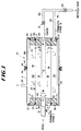
- Figure 1 is a schematic cross section of the module of the invention in which feed is passed to a central axial core and removed as retentate from the periphery of the module.
- FIG 2 is also a schematic cross section of the module of our invention as shown in Figure 1 but with the feed reversed, entering at the periphery of the module and exiting at the core.
- Figure 3 is a schematic cross section of another embodiment of our invention in which the partitioning wall member lies transversely through the shell along the axis of the module.
- Figure 4 is a sectional view of the module of Figure 3 illustrating the partitioning of the module into Sections I and II.
- FIGs 5, 6 and 7 are also sectional views of modules in the same manner as Figure 4 showing other possible arrangements of the partitioning wall member to increase the number of partitioned sections within the module to 3, 4 and 6, respectively.
- the hollow fiber membrane module of our invention includes at least two parallel sections of the fiber bundle, each section containing uniformly packed hollow fibers past which the feed material flows on the exterior of the fibers and sequentially in series through the sections. Each section is dimensioned so that its cross section is sufficiently small that uniform distribution of the feed is achieved as the feed mixture passes along the length of the fibers in each bundle section. A countercurrent flow pattern of the feed and permeate is achieved in each module section.
- Figure 1 represents schematically a preferred embodiment in which the fiber bundle sections are arranged concentrically in an annular form around an axial core and within the pressurizable module shell.
- a module 10 having an outer shell 11 of generally elongated cylindrical configuration and an axially positioned mandrel 12 which serves as a support for the fiber bundles which are not shown in Figure 1 but whose positioning will be described.
- Mandrel 12 can be a hollow tube or pipe through which feed mixture to be separated flows entering the module through conduit 13. If mandrel 12 is a hollow pipe, it is sealed at a suitable point such as by plug 14 or 16 so that the feed material is forced to enter the fiber bundle through openings 17.
- An elongated fiber bundle 18 is formed around mandrel 12 and an impermeable sheath or sleeve 19 surrounds the bundle 18 and effectively partitions the volume within the shell 11 occupied by fiber bundle 18 from the volume within the shell which is occupied by fiber bundle 20, which is placed around and is concentric with bundle 18.
- the thickness of each bundle 18 and 20 depends upon on the desired cross section of the fiber bundles to accommodate an even distribution of feed flowing through each of the sections.
- the individual fibers in bundles 18 and 20 can lie parallel to the axis of the module along which mandrel 12 lies, or the fibers can be wound helically or be interlaced, but they should be aligned for close and even packing and run generally along paths which extend from one end of each bundle to the other, so that passage of permeate within the bores of the fibers moves continuously in one direction toward one end of the fiber bundle or in the opposite direction as shown by broken line arrows 25, these directions being countercurrent to the flow of the feed mixture which is represented by the solid line arrows 15 shown within the module in Figure 1.
- the impermeable sheath or sleeve which serves as a wall member between the concentric annular bundle sections 18 and 20 contains passages 21 which permit feed material to flow from the section of the module containing fiber bundle 18 to the section of the module containing fiber bundle 20.
- Sheath 19 is preferably flexible to accommodate slight movements within the fiber bundles which are caused by changes of pressurization within the module.
- the sheath can be formed from an impermeable plastic, such as polyethylene or polypropylene, or a thin metal.
- sheath 22 is placed around the outside of fiber bundle 20. If sheath 22 is used then passages 23 are provided in the sheath in order to permit retentate to exit from the volume of the module which contains fiber bundle 20. Retentate then collects within space 24 which lies between the outside of fiber bundle 20 and the shell 11 of the module and this retentate is removed from the module by way of conduit 26 which communicates with space 24.
- Sheath 22 can be a wall of a plastic cartridge into which the fiber bundles are inserted and can be formed of material similar to that of sheath 19.
- One function of sheath 22 is to assist retaining the fibers of bundle 20 in place through repeated pressurizations and depressurizations as the module is used in its separation function. This cartridge does not have to be a pressurizable container, since there is very little pressure difference between the volume occupied by bundle 20 and space 24.
- Tubesheet 27 serves the fibers of both bundles 18 and 20 as does tubesheet 28 which is positioned on the opposite end of the fiber bundles. Potting resins for this function are well known in the art and are generally made from either an epoxy or polyurethane resin.
- the outer surfaces of tubesheets 27 and 28 are trimmed in a known manner to open up the ends of the fibers of bundles 18 and 20. Tubesheets 27 and 28 effectively seal off the bores of the fibers from their exteriors which lie between the tubesheets.
- O-rings 29 and 30 Assisting in this sealing of the space between the tubesheets are O-rings 29 and 30, positioned concentrically between the end of casing 11 and tubesheet 27, and O-rings 31 and 32 positioned concentrically between the other end of shell 11 and tubesheet 28.
- O-rings 29 and 30 are positioned to define and seal off annular collection zone 33 which is adjacent tubesheet 27 and in open communication with the bores of the fibers of bundle 20.
- O-ring 30 cooperating with the end of shell 11 and tubesheet 27 defines and seals off volume 34, which is adjacent tubesheet 27 and in open communication with the bores of the fibers of bundle 18.
- O-rings 31 and 32 cooperate with tubesheet 28 and the end of shell 11 to seal off and define an annular zone 36.
- zone 36 serves no function except to seal off the ends of the fibers of bundle 20, which pass through tubesheet 28.
- O-ring 32 cooperates with tubesheet 28 and the end of shell 11 to form a collection zone 37, which is in open communication with the bores of the fibers of bundle 18. Permeate passing from the bores of the fibers of bundle 18 into collection zone 37 can be removed from the shell by conduit 38, which is connected to communicate with zone 37. Likewise, permeate exiting from the bores of the fibers of bundle 20 into zone 33 can be removed by conduit 39 which communicates with zone 33.
- Conduit 40 is provided connected to permeate exit conduit 29 with valve 41 to communicate with volume 34 in order to permit part of the permeate exiting from the fiber bundle 20 to be used as a sweep gas through the bores of fiber bundle 18.
- the remainder of the permeate from fiber bundle 20 can be withdrawn by way of conduit 42 through valve 43.
- This permeate can, as subsequently described, be recycled to feed, vented, or collected for some other purpose.
- permeate flow direction is indicated by broken line arrows, e.g. arrow 25, and feed or feed retentate flow direction is indicated by solid line arrows, e.g. arrow 15.
- Alternative structures, such as flanged end sections for shell 11, can be employed as well.
- Feed air is passed through conduit 13 and enters the fiber bundle 18 through ports 17 which are positioned adjacent tubesheet 28. These openings 17 which are positioned immediately downstream of the potting resin boundary of tubesheet 28, distribute the feed air radially through the thickness of bundle 18.
- the feed gas travels lengthwise along the line of the axis of the module, through fiber bundle 18, as indicated by the solid line arrows in Figure 1 and passes into the volume occupied fiber bundle 20, through passages 21 which are positioned immediately adjacent tubesheet 27 at the opposite end of bundle 18 where the feed enters.
- This feed gas material which is the retentate from fiber bundle 18, becomes the feed gas for bundle 20.
- stage I separation which is followed immediately by stage II separation, which occurs in fiber bundle 20.
- stage II separation which occurs in fiber bundle 20.
- This retentate from stage I travels along the axial direction of bundle 20 as shown by the solid line arrows of Figure 1, moving in the direction opposite to that of the flow of feed gas in stage I.
- the retentate from fiber bundle 20 or stage II exits from the bundle through passages 23 in sheath or cartridge 22 and leaves the module through conduit 26 which communicates with volume 24 within shell 11.
- the permeate gas of stage I or bundle 18 travels, as shown by the broken line arrows, countercurrently to the flow of feed gas and exits from the bores of the fibers in bundle 18 into collection zone 39 and then is removed from the module by way of conduit 38.
- the permeate of stage II or of fiber bundle 20 passes countercurrently to the flow of feed gas and exits from the bores of the fibers of bundle 20 into zone 33 and then into conduit 29, through which it is removed from the module.
- the module design and construction therefore, permits the effective separation of feed gas, retentate, and permeates from two separate stages of the process which is practiced with the module.
- Figure 2 shows the same module structure as Figure 1, except for the external permeate conduits as will be described, but the operation of Figure 2 is such that feed gas is fed to the peripheral 24 volume of shell 11 through conduit 26 and exits from shell 11 through axial conduit 13 as retentate.
- the direction of the arrows internally of the module are reversed from that of Figure 1, showing the reverse flows of feed gas and permeate through the module.
- the result of this flow reversal is to make the separation occurring within fiber bundle 20 the first stage or stage I of the operation and the separation occurring within bundle 18 stage II of the separation.
- Permeate from stage I exiting from the bores of fiber bundle 20 into collection zone 36 adjacent tubesheet 28 is removed from the module by way of conduit 48 which communicates with zone 36.
- Volume 37 which is also adjacent tubesheet 28 is effectively sealed and does not communicate with any other volume of the module so that other sealing means can be employed to close the ends of the fiber bundle 18 which pass through tubesheet 28.
- Fiber bundle 18 At the opposite end of the module adjacent tubesheet 27, permeate from fiber bundle 18 exits the bores of the fibers into zone 34 which communicates with exit conduit 49. Fiber bundle 18, therefore, provides stage II of the separation so that the stage II permeate is removed through conduit 49, while a separate stage I permeate is removed through conduit 48.
- stage II permeate can be used as a sweep gas for passing through the bores of fiber bundle 20 by passing it through conduit 50 and valve 51 into volume 33 which communicates with the bores of fiber bundle 20.
- the remainder of stage II permeate can be withdrawn by conduit 52 through valve 53 and passed as a recycle to the feed gas or vented or used for some other purpose.
- a feed air would enter the module through conduit 26 and pass through passages in sheath 22 into the fiber bundle 20 immediately adjacent tubesheet 28, passing axially along the length of bundle 20.
- the retentate from this stage I passes into fiber bundle 18 through passages in sheath 19 adjacent tubesheet 27.
- This feed gas then passes axially along the length of bundle 18 and is removed through passages in mandrel 12 adjacent tubesheet 28 and exits through conduit 13. It can be seen that although the flow of feed gas is reversed from that shown in Figure 1, the module is readily adaptable for removal of permeates from both stage I and stage II of the separation in such a manner that countercurrent flows of feed gas on the shell side of the fibers and permeate in the bores of the fibers is insured.
- Figure 3 illustrates an alternative embodiment in which the wall barrier separating the fiber bundles into two separate sections is accomplished by a single flat wall member which passes from one side of the shell to the other through the axis of the module.
- An end view of this separating barrier is further illustrated in Figure 4 as a sectional view along lines 4-4 in Figure 3.
- shell 54 of the module illustrated has a feed conduit 56 for introduction of feed gas and conduit 57 for removal of retentate.
- Shell 54 houses fiber bundles 58 and 59 which are separated by barrier member 60, which is an impermeable member of material similar to the sheaths of Figures 1 and 2.
- Shell 54 and fiber bundles 58 and 59 separated by barrier 60 are also illustrated in Figure 4 in which there are formed sections I and II, which provides the two separating stages of the module.
- the fiber ends of both bundles 58 and 59 are imbedded in tubesheet 61 at one end and in tubesheet 62 at the opposite end.
- Conduit 73 communicating with zone 68 and conduit 72 communicating with zone 71 are used for removal of the permeates from the fiber bundles 58 and 59, respectively.
- feed gas enters the module through conduit 56 and passes through openings 74 distributed in sheath 76 adjacent to tubesheet 61 into the volume of the module which is occupied by fiber bundle 58.
- the feed gas passes axially through fiber bundle 58 toward tubesheet 62 as indicated by solid line arrow 55 and then passes through openings in barrier 60 by way of passages 77 into the volume of shell 54 occupied by bundle 59.
- Stage I of the separation occurs in bundle 58 and stage II of the separation occurs in bundle 59.
- Permeate of stage I passes through the bores of the fibers of bundle 58 as indicated by broken line arrow 65 and thence into volume 68 and is removed by conduit 73.
- Permeate from stage II passes into volume 71 from the bores of the bundle 59 and is removed by conduit 72.
- the fibers are laid down so that they run generally parallel to the axis of shell 54 filling the volumes illustrated for sections I and II ( Figure 4). All of the fibers of bundle 58 are completely contained within section I and all of the fibers of bundle 59 are completely contained within section II. The fibers follow a generally parallel path so that as permeate passes through the bores of the fibers in bundle 58, it moves toward tubesheet 61 and as permeate passes through the bores of fiber bundle 59 it moves toward tubesheet 62. In this manner countercurrent flows of the permeates and of the feed gas is assured.
- the solid line arrows illustrate the direction of flow of the feed gas and feed retentate and the broken line arrows indicate the direction of flow of the permeates.
- FIGs 3 and 4 multiple sections can be provided by providing barriers functioning in a manner similar to that of barrier 60 in Figures 3 and 4, but having different configurations as illustrated in Figures 5, 6 and 7 which are sectional end views of alternate embodiments.
- the volume contained within shell 79 is divided by a barrier 80 into sections I, II and III
- the volume contained within shell 81 is divided by barrier 82 into sections I, II, III, and IV.
- the volume of the shell 83 illustrated in Figure 7 is divided by barrier 84 into six separate separating sections which can be used sequentially by providing suitable passages through the barrier walls adjacent the tubesheets from one section into the other.
- the fiber bundles are formed by laying down fibers in a generally parallel fashion looping back and forth within each section. The fibers are opened to communicate with collection zones after they have been potted into single tubesheets at each end of the module.
- the module of this invention can be used in a simple 2-stage separation with the recovery of two separate permeates and a retentate.
- the module can be operated in order to recycle part of the permeate from stage II to the feed. This reduces permeate back pressure build-up in the bores of the fibers of stage I.
- the relatively high nitrogen content of the stage II permeate allows an increase in module productivity when at least a portion of this stream is recycled to feed.
- stage II permeate to sweep the bores of the stage I fiber bundle. This increases the efficiency of the module's performance.
- a preferred mode of operation is with the use of part of stage II permeate as recycle and part as a sweep gas to the bores of the fibers of stage I.
- the module design of this invention readily provides for accomplishing this result.
- the proportion of stage II permeate used as sweep, recycle and permeate vent is chosen to maximize productivity.
- the module of this invention also can readily be adapted to an operation in which the two stages have fibers of different sizes or different separation characteristics.
- the fiber size for stage I is chosen so that the permeate sweep from stage II does not cause excessive back pressure and in this case the bores of the fibers for stage I are slightly larger than the bores of the fibers for stage II. Operating in this fashion provides the advantage of enabling a higher packing density and higher area per unit volume of the module in stage II where the finer fiber is used. By using two different fiber sizes, optimum operation in each of the two stages of the module can be realized.
- the cross sections of the fiber bundles in each of the stages can be sized to provide a membrane area cross section area for optimum operation of the system.
- separate modules could also be sized differently, the economics of fabrication usually dictate that modules are made of identical sizes in order to keep manufacturing costs at a minimum.
- the module is combined with a suitable vacuum-producing device, such as a steam or water ejector or vacuum pump, in order to reduce the pressure and draw a partial vacuum to the bore side of stage II of the module.
- a suitable vacuum-producing device such as a steam or water ejector or vacuum pump
- both permeate streams can be provided with means for producing a vacuum within the fiber bores.
- conduit 57 would be connected through a passageway, not shown, to communicate with volume 69 adjacent tubesheet 61. This volume 69 communicates with the bores of the fibers in bundle 59 and a portion of the permeate from conduit 57 would sweep these bores toward the exit through tubesheet 62 into zone 71 with stage II permeate as it is removed through conduit 72.
- a portion of the stage II permeate can be used to sweep the bores of the fiber bundle in stage I as Illustrated in Figures 1 and 2 and also a portion of this permeate can be recycled to the compressor inlet of the feedstream.
- the module is, therefore, readily adaptable to provide a sweep gas to each of the fiber bundles on the bore side to improve the countercurrent flows of feed gas and permeate and also to recycle a portion of the stage II permeate to the feed. Proportions of these streams are readily chosen to maximize productivity and such an operation illustrates the versatility of the module of this invention.
- the module is particularly valuable when employing hollow fibers which are thin film composite or asymmetric membrane structures. Such hollow fibers are well known and are available commercially.
- the cross section of each bundle of the module can be dimensioned to optimize uniform distribution of feed gas across the fiber bundle for a range of flow rates of feed mixture.
- the flow rate of the useful product and its recovery (product/feed ratio) depend upon the intrinsic permselective properties of the membrane and the operating conditions of the module (pressure, temperature, product purity, flow pattern).
- the fibers are uniformly packed with a packing density of 39%.
- the length of the fibers between tubesheets 27 and 28 is 6 feet.
- the outer diameter of the module (inner edge of sheath 22) is 6 inches.
- the diameter of the sheath 19 between the two stages is 3.87 inches.
- the diameter of the control conduit 12 is 1 inch.
- Stage 1 including fiber bundle 20 has a cross-sectional area of 16.5 square inches and a membrane area of 808 square feet
- Stage 2 including fiber bundle 18 has a cross-sectional area of 11 square inches and a membrane area of 539 square feet.
- feed pressure of 150 psia, permeate pressure of 15 psia feed pressure of 150 psia, permeate pressure of 15 psia
- a computer simulation of the module performance shows that it can produce 433 scfh (standard cubic feet per hour, 60°F/l atmosphere) of retentate containing 97.7% nitrogen.
- the feed rate of air to Stage 1 is 1200 scfh and the feed rate to Stage 2 (retentate from Stage 1) is 695 scfh.
- a calculation shows that the superficial velocities at the inlets of Stage 1 and Stage 2 are 73 scfh/in2 and 63 scfh/in2 respectively.
- the superficial velocity in Stage 2 is substantially similar to that in
Landscapes
- Chemical & Material Sciences (AREA)
- Chemical Kinetics & Catalysis (AREA)
- Engineering & Computer Science (AREA)
- Analytical Chemistry (AREA)
- General Chemical & Material Sciences (AREA)
- Oil, Petroleum & Natural Gas (AREA)
- Water Supply & Treatment (AREA)
- Separation Using Semi-Permeable Membranes (AREA)
Applications Claiming Priority (2)
| Application Number | Priority Date | Filing Date | Title |
|---|---|---|---|
| US07/736,197 US5176725A (en) | 1991-07-26 | 1991-07-26 | Multiple stage countercurrent hollow fiber membrane module |
| US736197 | 1991-07-26 |
Publications (2)
| Publication Number | Publication Date |
|---|---|
| EP0524555A2 true EP0524555A2 (de) | 1993-01-27 |
| EP0524555A3 EP0524555A3 (en) | 1993-03-10 |
Family
ID=24958905
Family Applications (1)
| Application Number | Title | Priority Date | Filing Date |
|---|---|---|---|
| EP19920112280 Withdrawn EP0524555A3 (en) | 1991-07-26 | 1992-07-17 | Multiple stage countercurrent hollow fiber membrane module |
Country Status (4)
| Country | Link |
|---|---|
| US (2) | US5176725A (de) |
| EP (1) | EP0524555A3 (de) |
| KR (1) | KR950008632B1 (de) |
| RU (1) | RU2042409C1 (de) |
Cited By (1)
| Publication number | Priority date | Publication date | Assignee | Title |
|---|---|---|---|---|
| EP2172255A4 (de) * | 2007-07-02 | 2012-09-26 | Toshiba Kk | Hohlfasermembranentfeuchter |
Families Citing this family (62)
| Publication number | Priority date | Publication date | Assignee | Title |
|---|---|---|---|---|
| US5411662A (en) * | 1994-02-25 | 1995-05-02 | Praxair Technology, Inc. | Fluid separation assembly having an purge control valve |
| US5525143A (en) * | 1994-10-17 | 1996-06-11 | Air Products And Chemicals, Inc. | Hollow fiber membrane dryer with internal sweep |
| US5985146A (en) * | 1997-07-23 | 1999-11-16 | Trisep Corporation | Sanitary rigid shell spiral wound element |
| WO1999006137A1 (en) * | 1997-07-30 | 1999-02-11 | Dijk Christiaan P Van | Pure oxygen by diffusion |
| CA2311935A1 (en) * | 1997-12-22 | 1999-07-01 | Celgard, Llc | Device for removal of gas bubbles and dissolved gasses in liquid |
| US6070339A (en) * | 1998-10-23 | 2000-06-06 | Westinghouse Air Brake Company | Membrane air dryer with scheme to reduce air lost as sweep air |
| WO2000030742A1 (en) * | 1998-11-23 | 2000-06-02 | Zenon Environmental Inc. | Water filtration using immersed membranes |
| US20040007527A1 (en) * | 1998-11-23 | 2004-01-15 | Zenon Environmental Inc. | Membrane filtration device and process |
| US6153097A (en) * | 1999-05-26 | 2000-11-28 | Mg Generon | Internal staged permeator for fluid separation |
| US20010052494A1 (en) * | 1999-10-25 | 2001-12-20 | Pierre Cote | Chemical cleaning backwash for normally immersed membranes |
| US6635179B1 (en) * | 1999-12-30 | 2003-10-21 | Nephros, Inc. | Sterile fluid filtration cartridge and method for using same |
| JP2001202975A (ja) * | 2000-01-19 | 2001-07-27 | Honda Motor Co Ltd | 燃料電池用加湿装置 |
| EP1127606A1 (de) * | 2000-02-24 | 2001-08-29 | Stichting Energieonderzoek Centrum Nederland(ECN) | Membranmodul zur Trennung von fluiden Mischungen |
| DE10026344A1 (de) * | 2000-04-01 | 2001-10-04 | Membraflow Gmbh & Co Kg Filter | Filtermodul |
| RU2187359C2 (ru) * | 2000-04-14 | 2002-08-20 | Федеральное государственное унитарное предприятие Конструкторское бюро общего машиностроения им. В.П.Бармина | Устройство для осушки газов |
| CN1386070A (zh) * | 2000-07-07 | 2002-12-18 | 齐侬环境有限公司 | 多级过滤和软化模件以及除垢操作的简化 |
| US6702944B2 (en) | 2000-07-07 | 2004-03-09 | Zenon Environmental Inc. | Multi-stage filtration and softening module and reduced scaling operation |
| US20040129637A1 (en) * | 2000-07-07 | 2004-07-08 | Hidayat Husain | Multi-stage filtration and softening module and reduced scaling operation |
| FR2815886B1 (fr) | 2000-10-30 | 2002-12-06 | Hospal Ind | Faisceau de fibres creuses pour un appareil pour le traitement extracorporel du sang et du plasma et son procede de fabrication |
| FR2817485B1 (fr) * | 2000-12-06 | 2003-01-03 | Commissariat Energie Atomique | Decolmatage d'un filtre a fibres creuses fonctionnant en mode frontal |
| US6656585B2 (en) * | 2001-02-15 | 2003-12-02 | Hiroshi Takatsuji | Thread |
| JP3765531B2 (ja) * | 2001-03-30 | 2006-04-12 | 本田技研工業株式会社 | 加湿モジュール |
| US6755894B2 (en) | 2001-05-02 | 2004-06-29 | Praxair Technology, Inc. | Hollow fiber membrane gas separation cartridge and gas purification assembly |
| US6814780B2 (en) | 2001-05-02 | 2004-11-09 | L'air Liquide, Societe Anonyme A Directoire Et Conseil De Surveillance Pour L'etude Et L'exploitation Des Procedes Georges Claude | Hollow fiber membrane gas separation cartridge and gas purification assembly |
| US6502635B1 (en) | 2001-06-20 | 2003-01-07 | Chevron U.S.A. Inc. | Sub-sea membrane separation system with temperature control |
| CA2351272C (en) * | 2001-06-22 | 2009-09-15 | Petro Sep International Ltd. | Membrane-assisted fluid separation apparatus and method |
| US20040115489A1 (en) * | 2002-12-12 | 2004-06-17 | Manish Goel | Water and energy management system for a fuel cell |
| AU2004275627B2 (en) * | 2003-09-29 | 2007-08-09 | Asahi Kasei Chemicals Corporation | External pressure type hollow fiber membrane module |
| US7273549B2 (en) * | 2004-01-23 | 2007-09-25 | Geoscience Support Services Inc. | Membrane contactor apparatus including a module having hollow fiber membranes |
| US20050194315A1 (en) * | 2004-02-27 | 2005-09-08 | Adams Nicholas W.H. | Membrane batch filtration process |
| US20060118487A1 (en) * | 2004-12-07 | 2006-06-08 | Adams Nicholas W H | Membrane filtration process |
| US7918921B2 (en) * | 2005-02-04 | 2011-04-05 | Membrane Technology And Research, Inc | Gas separation membrane module assembly with residue manifold |
| US7534349B2 (en) * | 2005-09-02 | 2009-05-19 | Nephros, Inc. | Dual stage ultrafilter devices in the form of portable filter devices, shower devices, and hydration packs |
| US7717983B2 (en) * | 2005-10-18 | 2010-05-18 | Parker-Hannifin Corporation | Air separation module with load carrying center tube |
| US7775375B2 (en) * | 2005-11-03 | 2010-08-17 | Medica S.R.L. | Redundant ultrafiltration device |
| US7678177B2 (en) * | 2006-09-12 | 2010-03-16 | New York Air Brake Corporation | Membrane air dryer and sweep valve |
| US7790030B2 (en) * | 2006-12-20 | 2010-09-07 | Uop Llc | Multi-tube pressure vessel |
| US7871520B2 (en) * | 2007-12-18 | 2011-01-18 | Milton Roy Company | High-temperature membrane distillation |
| US7608185B2 (en) * | 2007-12-18 | 2009-10-27 | Hamilton Sundstrand Corporation | Hollow fiber membrane modules for use in distillation systems |
| US20100025219A1 (en) * | 2008-07-29 | 2010-02-04 | Milton Roy Company | System and method for membrane distillation with low reynolds numbers |
| US20100051549A1 (en) * | 2008-08-29 | 2010-03-04 | Milton Roy Company | Heat recuperating membrane distillation apparatus and system |
| US20100065496A1 (en) * | 2008-09-12 | 2010-03-18 | Milton Roy Company | Membrane distillation pressure control system and method |
| GB2477679A (en) * | 2008-10-30 | 2011-08-10 | Porous Media Corp | Venting and filtration systems with gas permeable membrane |
| EP2457640B1 (de) * | 2009-07-24 | 2015-03-11 | Honda Motor Co., Ltd. | Hohlfasermembranmodul für feuchtigkeitsaustausch |
| US20110180479A1 (en) * | 2010-01-27 | 2011-07-28 | Milton Roy Company | Zero liquid discharge water treatment system and method |
| US20110180383A1 (en) * | 2010-01-27 | 2011-07-28 | Milton Roy Company | Membrane distillation system and method |
| JP5591041B2 (ja) * | 2010-09-17 | 2014-09-17 | 三菱重工業株式会社 | 脱水装置に用いられる膜容器 |
| US9199191B2 (en) * | 2012-08-17 | 2015-12-01 | Ube Industries, Ltd. | Gas separation membrane module and method of replacing a hollow fiber element |
| US9545599B2 (en) * | 2013-02-28 | 2017-01-17 | Generon Igs, Inc. | Hybrid membrane system for gas streams with condensable hydrocarbons |
| US8945276B2 (en) * | 2013-06-07 | 2015-02-03 | Membrane Technology And Research, Inc. | Parallel feed gas separation membrane element assembly |
| DE102014104386B4 (de) * | 2014-03-28 | 2019-03-14 | Beko Technologies Gmbh | Gehäusekopf mit Spülluftregler |
| US10086326B2 (en) | 2016-03-31 | 2018-10-02 | Membrane Technology And Research, Inc. | Gas separation module and assembly |
| US9579605B1 (en) | 2016-03-31 | 2017-02-28 | Membrane Technology And Research, Inc. | Gas separation module and assembly |
| EP3456405A4 (de) * | 2016-05-11 | 2020-01-22 | Mitsubishi Chemical Cleansui Corporation | Hohlfasermembranmodul |
| US10512717B2 (en) | 2016-05-27 | 2019-12-24 | The Charles Stark Draper Laboratory, Inc. | Hemotransfiltration hollow fiber device |
| JP6780817B2 (ja) | 2016-11-08 | 2020-11-04 | Smc株式会社 | 除湿エレメント及びそれを有する除湿装置 |
| JP7231419B2 (ja) * | 2019-01-22 | 2023-03-01 | 日東電工株式会社 | 分離膜モジュール及びそれを用いた液体処理システム |
| US11103827B2 (en) | 2019-02-05 | 2021-08-31 | Generon Igs, Inc. | Two-stage gas separation unit contained within a single housing |
| US11446610B2 (en) | 2019-04-03 | 2022-09-20 | Generon Igs, Inc. | Gas separation membrane module with enhanced performance |
| US11339334B2 (en) * | 2020-02-06 | 2022-05-24 | Merichem Company | Multi-stage contacting process and apparatus |
| US12508549B2 (en) * | 2022-06-09 | 2025-12-30 | L'air Liquide, Societe Anonyme Pour L'etude Et L'exploitation Des Procédés Georges Claude | Gas separation membrane bundle with convertible flow configurations |
| WO2024121590A1 (en) * | 2022-12-05 | 2024-06-13 | Divigas Pte Ltd | Hollow fiber membrane module for hydrogen separation |
Family Cites Families (32)
| Publication number | Priority date | Publication date | Assignee | Title |
|---|---|---|---|---|
| DE123476C (de) * | 1960-09-19 | |||
| US3422008A (en) * | 1963-10-24 | 1969-01-14 | Dow Chemical Co | Wound hollow fiber permeability apparatus and process of making the same |
| FR2231421B1 (de) * | 1973-05-30 | 1976-05-07 | Rhone Poulenc Ind | |
| US4045851A (en) * | 1974-09-20 | 1977-09-06 | Albany International Corporation | Method of fabrication of hollow filament separatory module |
| US4220535A (en) * | 1978-08-04 | 1980-09-02 | Monsanto Company | Multi-zoned hollow fiber permeator |
| US4237596A (en) * | 1978-10-04 | 1980-12-09 | Standard Oil Company (Indiana) | Method of converting membrane separation units |
| US4208902A (en) * | 1978-12-20 | 1980-06-24 | Air Products And Chemicals, Inc. | Gas concentration analysis method and system |
| US4351092A (en) * | 1979-06-28 | 1982-09-28 | Albany International Corp. | Method of fabrication of coreless hollow filament separatory module |
| WO1981002835A1 (fr) * | 1980-04-10 | 1981-10-15 | Toray Industries | Dispositif du type a fibre creuse pour le traitement des fluides du corps |
| US4352736A (en) * | 1980-12-08 | 1982-10-05 | Toyo Boseki Kabushiki Kaisha | Wound flattened hollow fiber assembly having plural spaced core sections |
| FR2582536B1 (fr) * | 1985-05-29 | 1987-08-21 | Framatome Sa | Dispositif d'ultrafiltration d'un liquide sous pression et a haute temperature |
| US4865736A (en) * | 1985-12-10 | 1989-09-12 | Albany International Corp. | Hollow fiber separatory module with encased fiber bundle |
| US4676808A (en) * | 1985-12-18 | 1987-06-30 | Albany International Corp. | Module for multistage gas separation |
| US4752305A (en) * | 1986-10-30 | 1988-06-21 | The Dow Chemical Company | Device and method for separating individual fluids from a mixture of fluids |
| US4707267A (en) * | 1987-01-22 | 1987-11-17 | The Dow Chemical Company | Device and method for separating individual fluids from a mixture of fluids |
| JPS6456116A (en) * | 1987-08-26 | 1989-03-03 | Daikin Ind Ltd | Air dehumidifying device |
| JPS6456115A (en) * | 1987-08-26 | 1989-03-03 | Daikin Ind Ltd | Water vapor separation device |
| JPS6463020A (en) * | 1987-09-01 | 1989-03-09 | Daikin Ind Ltd | Membrane type gas separator |
| JPH01281125A (ja) * | 1988-04-30 | 1989-11-13 | Daikin Ind Ltd | 膜式気体分離装置 |
| JPH01281126A (ja) * | 1988-05-02 | 1989-11-13 | Daikin Ind Ltd | 膜式気体分離装置 |
| US4897191A (en) * | 1988-05-27 | 1990-01-30 | Zenon Environmental Inc. | Tubular membrane module with fluid shear protection |
| JPH0259015A (ja) * | 1988-08-25 | 1990-02-28 | Ube Ind Ltd | ガスの分離方法 |
| JPH0779954B2 (ja) * | 1988-08-25 | 1995-08-30 | 宇部興産株式会社 | ガス分離膜モジュール |
| US4880440A (en) * | 1988-09-12 | 1989-11-14 | Union Carbide Corporation | Hollow fiber multimembrane cells and permeators |
| GB8830107D0 (en) * | 1988-12-23 | 1989-02-22 | Boc Group Plc | Gas separation |
| US5059374A (en) * | 1989-02-09 | 1991-10-22 | The Dow Chemical Company | Method for sealing a hollow fiber membrane module in a case |
| US4961760A (en) * | 1989-02-09 | 1990-10-09 | The Dow Chemical Company | Hollow fiber membrane fluid separation device adapted for boreside feed |
| US4929259A (en) * | 1989-02-09 | 1990-05-29 | The Dow Chemical Company | Hollow fiber membrane fluid separation module for boreside feed |
| US5013331A (en) * | 1989-06-30 | 1991-05-07 | E. I. Du Pont De Nemours And Company | Permeator with selectable flow rates |
| JPH0386219A (ja) * | 1989-08-29 | 1991-04-11 | Ube Ind Ltd | 中空糸膜モジュール |
| US5013437A (en) * | 1989-10-30 | 1991-05-07 | The Dow Chemical Company | Hollow fiber membrane fluid separation device adapted for boreside feed which contains multiple concentric stages |
| US5026479A (en) * | 1990-02-13 | 1991-06-25 | Union Carbide Industrial Gases Technology Corporation | Fluid separation device |
-
1991
- 1991-07-26 US US07/736,197 patent/US5176725A/en not_active Expired - Fee Related
-
1992
- 1992-06-30 US US07/906,731 patent/US5288308A/en not_active Expired - Fee Related
- 1992-07-17 EP EP19920112280 patent/EP0524555A3/en not_active Withdrawn
- 1992-07-24 RU SU925052224A patent/RU2042409C1/ru active
- 1992-07-24 KR KR1019920013235A patent/KR950008632B1/ko not_active Expired - Fee Related
Cited By (1)
| Publication number | Priority date | Publication date | Assignee | Title |
|---|---|---|---|---|
| EP2172255A4 (de) * | 2007-07-02 | 2012-09-26 | Toshiba Kk | Hohlfasermembranentfeuchter |
Also Published As
| Publication number | Publication date |
|---|---|
| RU2042409C1 (ru) | 1995-08-27 |
| KR930001969A (ko) | 1993-02-22 |
| US5176725A (en) | 1993-01-05 |
| EP0524555A3 (en) | 1993-03-10 |
| KR950008632B1 (ko) | 1995-08-03 |
| US5288308A (en) | 1994-02-22 |
Similar Documents
| Publication | Publication Date | Title |
|---|---|---|
| US5176725A (en) | Multiple stage countercurrent hollow fiber membrane module | |
| KR940004620B1 (ko) | 유공섬유 다중막 셀 및 여과기 | |
| US5160042A (en) | Double ended hollow fiber bundle and fluids separation apparatus | |
| US5282964A (en) | Boreside feed hollow fiber membrane device | |
| US5837033A (en) | Hollow fiber membrane separation apparatus | |
| US5158581A (en) | Fluid separation membrane module with hollow fibers having segregated active surface regions | |
| US4687578A (en) | Fluid separation membranes | |
| US6755894B2 (en) | Hollow fiber membrane gas separation cartridge and gas purification assembly | |
| US5071552A (en) | Multiple bundle fluid separation apparatus | |
| KR940004619B1 (ko) | 나선형으로 감긴 유공섬유 투과성막 카트리지를 사용한 가스분리방법 | |
| US3455460A (en) | Permeability separatory apparatus and processes of making and using the same | |
| US3339341A (en) | Fluid separation process and apparatus | |
| US3422008A (en) | Wound hollow fiber permeability apparatus and process of making the same | |
| US5460720A (en) | Pleated membrane crossflow fluid separation device | |
| US3499062A (en) | Method of repairing leaks in fluid separation apparatus | |
| EP0234893B1 (de) | Rohrplatte für Permeationsvorrichtung mit spiralförmig gewickelten Hohlfasern | |
| US6814780B2 (en) | Hollow fiber membrane gas separation cartridge and gas purification assembly | |
| JPH04265111A (ja) | 膜を用いる乾燥方法及び装置 | |
| JPH04219127A (ja) | 流体分離装置 | |
| WO1993007958A1 (en) | Multiple bundle permeator | |
| US4865736A (en) | Hollow fiber separatory module with encased fiber bundle | |
| EP0226431B1 (de) | Hohlfasermodul für Trennungsverfahren | |
| US5207906A (en) | Membrane separation module | |
| US5234591A (en) | Counter-current flow hollow fiber permeator |
Legal Events
| Date | Code | Title | Description |
|---|---|---|---|
| PUAI | Public reference made under article 153(3) epc to a published international application that has entered the european phase |
Free format text: ORIGINAL CODE: 0009012 |
|
| PUAL | Search report despatched |
Free format text: ORIGINAL CODE: 0009013 |
|
| AK | Designated contracting states |
Kind code of ref document: A2 Designated state(s): DE ES NL |
|
| AK | Designated contracting states |
Kind code of ref document: A3 Designated state(s): DE ES NL |
|
| 17P | Request for examination filed |
Effective date: 19930506 |
|
| R17P | Request for examination filed (corrected) |
Effective date: 19930506 |
|
| 17Q | First examination report despatched |
Effective date: 19950628 |
|
| GRAH | Despatch of communication of intention to grant a patent |
Free format text: ORIGINAL CODE: EPIDOS IGRA |
|
| STAA | Information on the status of an ep patent application or granted ep patent |
Free format text: STATUS: THE APPLICATION IS DEEMED TO BE WITHDRAWN |
|
| 18D | Application deemed to be withdrawn |
Effective date: 19960712 |