EP0525254A1 - Convoyeur sur rails, notamment convoyeur discontinu pour articles - Google Patents
Convoyeur sur rails, notamment convoyeur discontinu pour articles Download PDFInfo
- Publication number
- EP0525254A1 EP0525254A1 EP91250208A EP91250208A EP0525254A1 EP 0525254 A1 EP0525254 A1 EP 0525254A1 EP 91250208 A EP91250208 A EP 91250208A EP 91250208 A EP91250208 A EP 91250208A EP 0525254 A1 EP0525254 A1 EP 0525254A1
- Authority
- EP
- European Patent Office
- Prior art keywords
- support
- conveyor according
- longitudinal axis
- conveyor
- tilting
- Prior art date
- Legal status (The legal status is an assumption and is not a legal conclusion. Google has not performed a legal analysis and makes no representation as to the accuracy of the status listed.)
- Withdrawn
Links
- 230000008878 coupling Effects 0.000 claims 1
- 238000010168 coupling process Methods 0.000 claims 1
- 238000005859 coupling reaction Methods 0.000 claims 1
- 210000002414 leg Anatomy 0.000 description 18
- 238000005516 engineering process Methods 0.000 description 6
- 238000009826 distribution Methods 0.000 description 5
- 238000003860 storage Methods 0.000 description 5
- 230000032258 transport Effects 0.000 description 5
- 238000013461 design Methods 0.000 description 4
- 238000010276 construction Methods 0.000 description 3
- 238000011161 development Methods 0.000 description 3
- 230000000694 effects Effects 0.000 description 3
- 238000004519 manufacturing process Methods 0.000 description 3
- 238000000034 method Methods 0.000 description 3
- 230000008569 process Effects 0.000 description 3
- 206010016275 Fear Diseases 0.000 description 2
- 230000001133 acceleration Effects 0.000 description 2
- 230000001154 acute effect Effects 0.000 description 2
- 238000013459 approach Methods 0.000 description 2
- 230000008859 change Effects 0.000 description 2
- 230000005484 gravity Effects 0.000 description 2
- 210000000689 upper leg Anatomy 0.000 description 2
- 240000006829 Ficus sundaica Species 0.000 description 1
- 240000000528 Ricinus communis Species 0.000 description 1
- 235000004443 Ricinus communis Nutrition 0.000 description 1
- 230000009471 action Effects 0.000 description 1
- 230000002411 adverse Effects 0.000 description 1
- 230000000712 assembly Effects 0.000 description 1
- 238000000429 assembly Methods 0.000 description 1
- 230000003542 behavioural effect Effects 0.000 description 1
- 230000015556 catabolic process Effects 0.000 description 1
- 238000005352 clarification Methods 0.000 description 1
- 238000006731 degradation reaction Methods 0.000 description 1
- 230000002349 favourable effect Effects 0.000 description 1
- 230000006872 improvement Effects 0.000 description 1
- 238000012423 maintenance Methods 0.000 description 1
- 238000003825 pressing Methods 0.000 description 1
- 238000012545 processing Methods 0.000 description 1
- 238000005096 rolling process Methods 0.000 description 1
- 230000001960 triggered effect Effects 0.000 description 1
- 238000011144 upstream manufacturing Methods 0.000 description 1
Images


Classifications
-
- B—PERFORMING OPERATIONS; TRANSPORTING
- B65—CONVEYING; PACKING; STORING; HANDLING THIN OR FILAMENTARY MATERIAL
- B65G—TRANSPORT OR STORAGE DEVICES, e.g. CONVEYORS FOR LOADING OR TIPPING, SHOP CONVEYOR SYSTEMS OR PNEUMATIC TUBE CONVEYORS
- B65G47/00—Article or material-handling devices associated with conveyors; Methods employing such devices
- B65G47/74—Feeding, transfer, or discharging devices of particular kinds or types
- B65G47/94—Devices for flexing or tilting travelling structures; Throw-off carriages
- B65G47/96—Devices for tilting links or platform
- B65G47/962—Devices for tilting links or platform tilting about an axis substantially parallel to the conveying direction
-
- B—PERFORMING OPERATIONS; TRANSPORTING
- B07—SEPARATING SOLIDS FROM SOLIDS; SORTING
- B07C—POSTAL SORTING; SORTING INDIVIDUAL ARTICLES, OR BULK MATERIAL FIT TO BE SORTED PIECE-MEAL, e.g. BY PICKING
- B07C3/00—Sorting according to destination
- B07C3/02—Apparatus characterised by the means used for distribution
- B07C3/08—Apparatus characterised by the means used for distribution using arrangements of conveyors
- B07C3/082—In which the objects are carried by transport holders and the transport holders form part of the conveyor belts
- B07C3/087—In which the objects are carried by transport holders and the transport holders form part of the conveyor belts the objects being taken up in transport files or holders which are not part of the conveyor belts
Definitions
- the invention relates to a conveyor, in particular a discontinuous conveyor for general cargo, with a rail guide, possibly with various switches, along which the individual conveyor unit (s) is (are) to be moved in a self-propelled manner, and with (at least) one delivery station, at which the goods to be transported (controlled) are to be delivered.
- sorters In the context of conveyor and distribution technology, i.a. also known as sorters for short, in which the piece goods are placed at at least one feed point (but often also at several task points) in such a way that they are each placed on the essentially horizontal support surface of a conveying element in the conveyed state.
- the supporting surface of the conveying elements is "essentially" horizontal in the conveying state, this should express that the supporting surface can also be curved or angled in a bowl-like manner.
- the conveyor line can run in a horizontal plane, but also obliquely to the horizontal or in space, whereby care must be taken to ensure that the piece goods do not accidentally slide off the wings.
- the main task of sorters is to deliver the piece goods to one of several delivery stations located to the side of the conveyor track in order to sort them according to certain criteria.
- this can be, for example, sorting by postcode or, in the case of a sorter used at an airport, sorting checked baggage according to the destination or the like.
- the general cargo parts are generally provided with a code before they are placed on the sorter, or they have a label from the start that can be read by a reader after their job, the code or label being assigned to a specific feed station and by certain Devices are ensured that a piece of cargo assigned to a particular delivery station is discharged laterally from the sorter and at the delivery point in question - generally via a slide - reaches a conveyor with a conveyor device running transversely to the sorter, from which it is conveyed for further processing .
- (electric) monorails are known, in which a so-called monorail trolley (usually with an electric trolley) or the like directly on (at least) one crane rail. is to be moved (the trolley can also be moved by pressing or pulling the load on short travel paths), whereby the (monorail) trolleys are hanging trolleys, i.e. those trolleys whose loading equipment (such as a Load hook or the like) hangs down from the trolley (located / movable) under the rail in question.
- monorail trolley usually with an electric trolley
- the trolley can also be moved by pressing or pulling the load on short travel paths
- the (monorail) trolleys are hanging trolleys, i.e. those trolleys whose loading equipment (such as a Load hook or the like) hangs down from the trolley (located / movable) under the rail in question.
- the present invention relates to a conveyor (more precisely, a conveyor system) which, if you like, "lies” (technically) between the two aforementioned types of conveyor, but is more likely to be associated with the so-called distribution technology in terms of application technology than it has been for some time only for postal systems, rough mail order companies or the like. Are common, but increasingly also in the baggage storage of airports or the like. are used.
- the present invention is therefore based on the object of creating a conveyor or a conveyor system with which the object indicated above as an example, but also a large number / numerous other comparable tasks, can be solved in a technically and economically satisfactory manner.
- a / the conveying means - preferably on its upper side - is provided with a tilting conveying element.
- the / each conveying element is provided with its own drive, and preferably with a (remotely) controllable drive or its own (partial) control, by means of which the relevant good unit (i.e., for example, and in particular a General cargo part such as a suitcase) can be "targeted" or controlled directly to an aircraft or a cargo distribution station located upstream of an aircraft.
- the relevant good unit i.e., for example, and in particular a General cargo part such as a suitcase
- a horizontal reference plane running between the support element on the one hand and the support part on the other hand runs mirror-symmetrically to the longitudinal axis of the bearing journal and that in the tilting conveyor element according to DE-PS 36 02 861 is journal-shaped mig trained support element is firmly connected to the support member.
- the tilting conveyor element known from DE-PS 36 02 861 - just as in the tilting conveyor element known from WO 81/01 999 - the fixedly arranged on the underside of the support element, obliquely downward, rotatably mounted Bearing pin connected to the pin-shaped support element by a cardan joint, the axis of rotation of the cardan joint extending at right angles to the longitudinal axis of the pin-shaped support element running in the vertical plane in which the longitudinal axes of the bearing pin and the pin-shaped support element run in the conveyed state.
- the tilting conveyor element known from DE-PS 36 02 861 which differs very seriously from the previously known state of the art in terms of both its construction and its mode of operation, has hardly changed in practice as regards its mode of operation proven to be in need of improvement, but in terms of production technology, especially with regard to the cardan joint arranged between the bearing journal on the one hand and the journal-shaped support element on the other hand, it presents considerable difficulties which are system-inherent and accordingly cannot be eliminated. These difficulties lie - quite apart from the very considerable costs of the universal joint, which make up about 50% (!) Of the total costs of the entire tilting conveyor element - in particular in the tolerances to be demanded (and last but not least the associated manufacturing costs).
- This setting is probably based on the fear that a general cargo conveyor, the supporting elements of which already behave appropriately when it starts operating, will change to a state more or less at short notice due to normal, normal wear and tear, in that the individual conveying elements will fade like wilted flowers due to the feared deflection of their storage behave and in each case unintentionally and unsystematically already tilted sideways (even if only slightly), although ultimately there are fears that this behavior could increase to such an extent over the course of a relatively short operating time that it would then also disadvantageously occur affects the operating behavior, so that general cargo parts already slide off the wing in front of the controlled delivery point.
- the point of the wing which is penetrated by the longitudinal axis of the bearing journal does not remain stationary, but becomes controlled when the piece goods are delivered due to the rotation of the carrier element about the longitudinal axis of the journal and the one taking place about the joint Swiveling of the bearing pin relative to the support pin at the same time moved to the side, down and forwards, so that when the tilting rotation takes place, the wing executes a movement from its horizontal transport position in the conveyed state into its final delivery position, which moves the piece goods part in the direction of the delivery point accompanied and impressed him with a speed component directed transversely to the conveying direction.
- the longitudinal axis of the support pin can fundamentally run at a different angle to the horizontal than the longitudinal axis of the bearing pin, it has proven to be particularly expedient if the two longitudinal axes are mirror-symmetrical to one another in the conveyed state of the support element with respect to a horizontal reference plane running between the support element and the support part run, so - starting from their intersection - are arranged in a V-shape in a side view.
- a tilting element is preferably arranged between the supporting element and the support part of the conveying element in order to generate the rotation of the bearing journal, which is fixedly connected to the supporting element, about the longitudinal axis thereof, as well as the controlled pivoting movement of the bearing journal relative to the supporting journal, when the part of the piece is being delivered from the supporting surface of the conveying element , which is rotatably mounted on the bearing journal and the support journal and is arranged immovably in the longitudinal direction of the two journals.
- the tilting element can be designed as a V-shaped tubular body, one (first) leg of which is concentric with the bearing journal or its longitudinal axis and the other (second) leg of which is concentric with the supporting journal or its longitudinal axis, the the two end faces of the tilting element, each running at right angles to the respective longitudinal axis, are preferably opposite each other with a small space between a parallel surface of the support element or of the support part, and the tilting element can in each case be sealed off from the support element or from the support part, around the bearing points and the joint connecting the two pins to protect against pollution.
- the tilting element is expediently locked against rotation by means of a releasable locking means, the locking means being unlocked by means of an unlocking means which is arranged at each delivery point and can be operated in a controlled manner.
- the tilting element can then be rotated in a controlled manner about the longitudinal axis of the support pin by actuating an actuating means arranged at a delivery point, which on the one hand results in pivoting of the bearing pin about the longitudinal axis of the support pin and on the other hand causes rotation of the trunnion about its longitudinal axis.
- this has along a (generally rail-shaped trained) guide movable support part in the tilting conveyor element according to the invention (instead of the support pin present in the subject of DE-PS 36 02 861) on a support sleeve which concentrically surrounds the lower end portion of the tilting element, as will be explained in more detail below.
- the support part can be formed in the form of a (rotated) E in a side plan view (that is to say seen transversely to the vertical plane of symmetry of the tilting conveying element), the center leg of the support part being the bearing point for the lower end section can form the tilting element and the two outer legs of the E-shaped support part can each be (articulated) connected to the support element.
- This highly preferred embodiment has proven to be extremely useful in the context of extensive development work, in particular for an embodiment in which the central leg of the support part forming the bearing point for the lower end section of the tilting element - as already explained above - is designed as a support bushing.
- the two outer legs of the support part can preferably be aligned with one another, and the vertical central plane of symmetry of the two outer legs of the support part is expediently in the vertical plane of symmetry of the tilting conveying element according to the invention, which runs in the conveying direction.
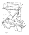
- Fig. 1 shows a generally designated 1 'conveyor for an (discontinuous) conveyor for piece goods according to the invention with a rail guide 2', along which the individual conveyor unit (s) can be moved along by means of a control, not shown, in a self-propelled manner (are), and with at least one delivery station (which will be discussed further below), at which the piece goods part 4 to be transported by a conveying means 1 'is to be delivered (controlled thereon).
- the piece goods parts 4 are each to be placed on the support surface 3 of a conveying element 1 at a plurality of feed points (not shown in the drawing) and, by inclining the horizontal support surface 3 in the conveyed state, optionally to be delivered laterally to the conveying direction 9 at one of a plurality of dispensing stations provided along the conveying path.
- Such a delivery station 10 is shown schematically in FIG. 2.
- a delivery station 10 In addition to devices by means of which a delivery of a piece goods part 4 conveyed by a specific conveying element 1 is to be triggered, it contains a chute 11 which runs obliquely to the horizontal and which is arranged such that a General cargo part 4 to be dispensed comes down onto the chute 11 when sliding down from the wing 3 of the conveying element 1 in question, and from there is fed onto a conveyor 12 of the delivery station 10, which conveys the relevant general cargo part 4 according to arrow 13 transversely to the conveying direction according to arrow 9.
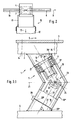
- Fig. 3.1 shows in a considerably enlarged, somewhat schematic side view, compared to FIGS. 1 and 2, a conveying element 1, the support element 2 of which is connected to the supporting surface 3 by means of connecting means 14, only the center lines of which are shown, for supporting a piece part 4 .
- a bearing journal 15 of the conveying element 1 extends obliquely downward from the underside of the supporting element 2, the longitudinal axis of which is designated by 16.
- the support element 2, which is firmly connected to the support surface 3, is rotatably supported in a manner described in detail below by means of the bearing pin 15 relative to the support part 6 about the longitudinal axis 16, specifically by means of a bearing 17, which in the present case is a Rolling bearing acts, the inner ring is fixedly attached to the bearing journal 15, and the outer ring is connected to a tilting element 18 which essentially forms the support device 5 and which is described in more detail below.
- the longitudinal axis 16 runs with the axis of symmetry 19 (see FIG. 2) of the support element 2 or its support surface 3 extending in the conveying direction 9 and in a common vertical plane and includes an acute angle a with the section of the support surface 3 lying forward in the conveying direction 9.
- the bearing pin of the conveying element 1 which is fixedly connected to the support element 2, can be pivoted in a controlled manner about a support pin 22 arranged at an angle to its longitudinal axis 16, as will become apparent from the further description.
- the longitudinal axis 20 of the support pin 22 runs in the conveyed state of the support element 2, that is, with the horizontal support surface 3, in the same plane (starting plane) as the longitudinal axis 16 and the axis of symmetry 19 of the support element 2. Otherwise, the longitudinal axis 20 extends in the conveyed state of the support element 2 with respect to. a horizontal reference plane 21 running between the support element 2 and the support part 6, mirror-symmetrical to the longitudinal axis 16 of the bearing journal 15, the angle a to the horizontal therefore being equal and being 60 in the exemplary embodiment shown.
- the bearing pin 15 of the conveying element 1 is articulated at its lower end to the support pin 22, which stands at an angle from the support part 6 and is firmly connected to the support part 6. Between the tilting element 18 and the support pin 22, a bearing is arranged in a manner analogous to that of the bearing pin 15, which for the sake of simplicity is not shown in detail in the drawing.
- the bearing pin 15 is connected to the support pin 22 of the conveying element 1 by a universal joint 23.
- One axis of rotation 24 of the universal joint 23 runs in the starting plane, in which the two longitudinal axes 16, 20 are in the transport state and in which the axis of symmetry 19 of the wing 3 runs in the conveyed state.
- the axis of rotation 24 of the cardan joint 23 extending in the output plane of the two longitudinal axes 16, 20 is an axis which is perpendicular to the longitudinal axis 20 of the support pin 22, while the other axis of rotation 25 of the cardan joint 23 is, of course, in turn arranged at right angles to the axis of rotation 24 .
- the tilting element 18 arranged between the supporting element 2 and the supporting part 6 of the conveying element 1 is rotatably mounted on the bearing pin 15 and on the supporting pin 22 by means of a bearing (for example 17), but in each case in the longitudinal direction of the pin 15 or 22 or their longitudinal axes 16 or 20 are not displaceable.
- the tilting element 18 is designed as a V-shaped tubular body, the upper (first) leg 18 'facing the supporting element 2 runs concentrically to the bearing journal 15, and the second leg 18' 'runs concentrically to the support journal 22.
- the two are each perpendicular to the respective longitudinal axis 16 or 20 end faces 26 'or 26 "of the tilting element 18 are arranged opposite each other with a small space 27 on a parallel surface 28' or 28" of the support element 2 or the support part 6, the spaces 27 being each by means of an in the seal, not shown, are sealed.
- the tilting element 18 is locked against rotation on the support part 6 by means of a locking means 29 only shown schematically in FIG. 3. Since the tilting element 18 cannot rotate about the longitudinal axis 20 in the locked state, the supporting element 2 is accordingly also locked via the two pins 15, 22 and the universal joint 23 connecting them.
- the locking means 29 of the conveying element 1 is to be unlocked by means of an unlocking means which is arranged at each delivery station 10 and can be operated in a controlled manner. Such unlocking can take place, for example, in that a lever 30 is articulated on the tilting element 18 according to FIG.
- a corresponding lever 30 is of course arranged on each side or a component is provided which is to be actuated on both sides of the conveying path at a delivery station 10 for the purpose of unlocking the locking means 29.
- the tilting element 18 is pivoted about the longitudinal axis 20 of the support pin 22 in a controlled manner by means of an actuating means arranged at the relevant delivery station 10. This can take place, for example, in that the roller 32 of the lever 29 moves into a guide rail arranged at the delivery station 10, which is curved so that when the roller 32 passes, the tilting element 18 rotates about the longitudinal axis 20.
- the support surface 3 is rotated both about the longitudinal axis 20 and about the longitudinal axis 16, which in this case about the longitudinal axis 20 or
- the support pin 22 is pivoted so that overall there is a geometrically somewhat complicated movement of the supporting surface 3 of the supporting element 2 or of the conveying element 1 which supports a general cargo part 4, in which the supporting surface 3 is brought into an inclined position towards the delivery side, but at the same time is lowered in the center and is moved forward during the rotation, so that the wing initially accompanies the general cargo part 4 when dispensing with a corresponding acceleration and the cargo part 4 is transferred in an extremely gentle manner to the downstream slide 11 (see FIG. 2) becomes.
- the bearing journal 15 of the tilting conveyor element 1 in the configuration according to FIGS. 3.2 and 4 is not at its free lower end section (via a universal or universal joint or possibly a ball joint) rigidly connected to the support part 6 support bush 34, but connected to this only via the tilting element 18 and at a greater distance from the longitudinal axis 20 arranged outer legs 35 and 36 of the support part 6, which are integrally formed with the support part 6.
- a universal or universal joint or possibly a ball joint rigidly connected to the support part 6 support bush 34
- the support part 6 is in the form of an E in lateral top view, the geometric web of which is rotated from the vertical by the angle a, the angle a being the (acute) angle , under which the longitudinal axes 15 and 20 each run mirror-symmetrically to the horizontal.
- the middle leg of the E-shaped support part 6 forms the support bush 34 and thus the bearing point for the lower end section 18 ′′ of the tilting element 18, while the two outer legs 35, 36 of the E-shaped support part 6 are each movably connected to the support element 2.
- the two outer legs 35, 36 of the support part 6 are aligned with one another in a vertical plane, specifically in the vertical plane of symmetry of the tilting conveyor element 1. They each have a recess 37 and 38 on their upper end section (see in particular FIGS. 4a and 4b ), in each of which a guide cam 39 or 40 of the support device 5 or the support element 2 is guided.
- the recesses 37, 38 of the outer legs 35, 36 are designed as elongated holes, the longitudinal axes 41 and 42 of which lie in the vertical plane of symmetry.
- the guide cams 39, 40 are designed as rollers, each with an elastic jacket, so that with a relative movement of the guide cams 39, 40 in the recesses 37, 38 practically no noise and i.ü. the tolerance issues are easily mastered in this way because of the elasticity.
- the more than rollers designed guide cams 39, 40 are each arranged on a guide cam holder 43 or 44 which is fixedly connected to the support device 5 or the support element 2, the axes 45 and 46 forming the central axis of the guide cams 39, 40 to each other are aligned and the guide cam axes 45, 46 can be seen in the vertical plane of symmetry.
- the guide cam holders 43, 44 functionally belong to the support device 5 or the support element 2 and could accordingly be functionally integrally formed therewith, as can be seen in particular from FIG. 4, they are designed as a disk 43 or bushing 44 for assembly to facilitate or to enable at all.
- the tilting element 18 is immovable in the longitudinal direction of the longitudinal axes 16 or 20 (axially), but it is of course rotatable overall to initiate the tilting movement at a delivery station 10 and to perform as this will be explained further.
- the tilting element 18 is recognizably designed as a V-shaped tubular body, the upper leg 18 'of which is concentric with the bearing journal 15 and thus its longitudinal axis 16 and the lower leg 18' 'of which runs concentrically with the longitudinal axis 20 of the support bush 34, but does not surround it concentrically, as is the case with the embodiment according to DE-PS 36 02 861 is the case, but rather acts as a bearing journal relative to the support bush 34, as can be seen in particular from the illustration in the lower part of FIG. 4.
- the tilting element 18 is locked against rotation on the support part 6 by means of a locking means not shown in detail in the drawing. Since the tilting element 18 cannot rotate about the longitudinal axis 20 of the support bushing 34 in the locked state, the support element 2 is accordingly also locked.
- the locking means of the tilting conveying element 1, which is not shown in detail in the drawing, can be unlocked by means of an unlocking means, which is arranged at each delivery station 10 and can be operated in a controlled manner.
- Such unlocking can take place, for example, in that on the tilting element 18 according to FIGS. 5 and 6 a lever 30 is articulated on a pivot axis 31, which with its laterally projecting free end, to which a roller 32 can expediently be attached that delivery station 10, at which the conveying element 4 is to deliver the piece goods part 4 transported by it, drives onto a ramp and is pivoted up about the pivot axis 31 in the direction of the arrow 33, whereby the lever 30 acts on the locking means 29 and unlocks it.
- a corresponding lever 30 is of course arranged on each side or a component is provided which is to be actuated on both sides of the conveyor line at a delivery station 10 for the purpose of unlocking the unlocking means.
- the emptying end position according to FIG 5 and 6, not shown, arranged on the other side of the tilting element 18 corresponds to a lever 30 at a delivery station 10, while actuation of the lever 30 shown in FIGS. 5 and 6 would cause a tilting to the other side.
- the support surface 3 is rotated about the longitudinal axis 16.
- the bearing journal 15 (and thus the support element 2 with its Wing 3) pivoted in a controlled manner relative to the support element 34, so that overall there is a geometrically somewhat complicated movement of the wing of the support element 2 supporting a piece goods part 4, in which the wing 3 is brought into an inclined position towards the delivery point, but at the same time lowered in the center and is moved forward during the rotation, so that the wing 3, the piece goods part 4 at the time of delivery initially by means of a corresponding acceleration accompanied and the piece goods part 4 is transferred in an extremely gentle manner to the downstream slide 11 (see FIG. 2).
- the axis 45-46 (see FIG. 4) is also pivoted clockwise, whereby the roller-shaped guide cam 39 according to the arrow 47 shown in FIG. 4 a in the recess 37 in the form of an elongated hole in the outer leg 35 of the support part 6 obliquely upwards and in a corresponding manner the guide cam 40 in the associated recess 38 also in the form of an elongated hole in the outer leg 36 is moved obliquely downward according to arrow 48 (see FIG. 4 b).
- the manufacturing costs of such a tilting conveyor element 1 compared to an embodiment according to DE-PS 36 02 861 by approx 50% (!) are to be reduced and - as stated - not accept any disadvantages, but even more advantageous effects can be achieved, so that, according to the invention, a tilting conveying element has been created which not only meets the conveying requirements - Includes extremely gentle handling of the general cargo parts 4 - takes into account in an excellent manner, but takes into account all requirements in a technical as well as in an economic manner.
Landscapes
- Engineering & Computer Science (AREA)
- Mechanical Engineering (AREA)
- Discharge Of Articles From Conveyors (AREA)
Priority Applications (1)
| Application Number | Priority Date | Filing Date | Title |
|---|---|---|---|
| EP91250208A EP0525254A1 (fr) | 1991-07-25 | 1991-07-25 | Convoyeur sur rails, notamment convoyeur discontinu pour articles |
Applications Claiming Priority (1)
| Application Number | Priority Date | Filing Date | Title |
|---|---|---|---|
| EP91250208A EP0525254A1 (fr) | 1991-07-25 | 1991-07-25 | Convoyeur sur rails, notamment convoyeur discontinu pour articles |
Publications (1)
| Publication Number | Publication Date |
|---|---|
| EP0525254A1 true EP0525254A1 (fr) | 1993-02-03 |
Family
ID=8208139
Family Applications (1)
| Application Number | Title | Priority Date | Filing Date |
|---|---|---|---|
| EP91250208A Withdrawn EP0525254A1 (fr) | 1991-07-25 | 1991-07-25 | Convoyeur sur rails, notamment convoyeur discontinu pour articles |
Country Status (1)
| Country | Link |
|---|---|
| EP (1) | EP0525254A1 (fr) |
Cited By (4)
| Publication number | Priority date | Publication date | Assignee | Title |
|---|---|---|---|---|
| DE102014108207A1 (de) * | 2014-06-11 | 2015-12-17 | Schoeller Allibert Gmbh | Transportmittel, Transport- und Verteilersystem und Verfahren zum Transportieren und Verteilen von Gütern |
| DE102016111357A1 (de) * | 2016-06-10 | 2017-12-14 | Weber Maschinenbau Gmbh Breidenbach | Vorrichtung zum Transport von Objekten |
| CN109047000A (zh) * | 2018-09-20 | 2018-12-21 | 民航成都物流技术有限公司 | 一种动态分拣装置及控制方法 |
| CN109100528A (zh) * | 2018-08-09 | 2018-12-28 | 迈克医疗电子有限公司 | 反应杯导向装置 |
Citations (5)
| Publication number | Priority date | Publication date | Assignee | Title |
|---|---|---|---|---|
| GB1331440A (en) * | 1970-10-22 | 1973-09-26 | Ato Inc | Conveyor carriage |
| FR2355577A2 (fr) * | 1976-06-22 | 1978-01-20 | Geci | Procede nouveau et installation applicables au tri de paquets |
| DE8714976U1 (de) * | 1986-11-10 | 1988-02-04 | Canziani, Francesco, San Macario, Varese | Sortiermaschine |
| DE3602861C2 (fr) * | 1986-01-31 | 1988-04-28 | Bernhard Beumer Maschinenfabrik Kg, 4720 Beckum, De | |
| EP0387427A1 (fr) * | 1989-03-16 | 1990-09-19 | Bernhard Beumer Maschinenfabrik KG | Convoyeur à plateaux basculants pour des objets |
-
1991
- 1991-07-25 EP EP91250208A patent/EP0525254A1/fr not_active Withdrawn
Patent Citations (5)
| Publication number | Priority date | Publication date | Assignee | Title |
|---|---|---|---|---|
| GB1331440A (en) * | 1970-10-22 | 1973-09-26 | Ato Inc | Conveyor carriage |
| FR2355577A2 (fr) * | 1976-06-22 | 1978-01-20 | Geci | Procede nouveau et installation applicables au tri de paquets |
| DE3602861C2 (fr) * | 1986-01-31 | 1988-04-28 | Bernhard Beumer Maschinenfabrik Kg, 4720 Beckum, De | |
| DE8714976U1 (de) * | 1986-11-10 | 1988-02-04 | Canziani, Francesco, San Macario, Varese | Sortiermaschine |
| EP0387427A1 (fr) * | 1989-03-16 | 1990-09-19 | Bernhard Beumer Maschinenfabrik KG | Convoyeur à plateaux basculants pour des objets |
Cited By (6)
| Publication number | Priority date | Publication date | Assignee | Title |
|---|---|---|---|---|
| DE102014108207A1 (de) * | 2014-06-11 | 2015-12-17 | Schoeller Allibert Gmbh | Transportmittel, Transport- und Verteilersystem und Verfahren zum Transportieren und Verteilen von Gütern |
| DE102016111357A1 (de) * | 2016-06-10 | 2017-12-14 | Weber Maschinenbau Gmbh Breidenbach | Vorrichtung zum Transport von Objekten |
| CN109100528A (zh) * | 2018-08-09 | 2018-12-28 | 迈克医疗电子有限公司 | 反应杯导向装置 |
| CN109100528B (zh) * | 2018-08-09 | 2024-02-20 | 迈克医疗电子有限公司 | 反应杯导向装置 |
| CN109047000A (zh) * | 2018-09-20 | 2018-12-21 | 民航成都物流技术有限公司 | 一种动态分拣装置及控制方法 |
| CN109047000B (zh) * | 2018-09-20 | 2024-02-06 | 民航成都物流技术有限公司 | 一种动态分拣装置及控制方法 |
Similar Documents
| Publication | Publication Date | Title |
|---|---|---|
| DE3908632C1 (fr) | ||
| DE3602861C2 (fr) | ||
| EP1454856B1 (fr) | Convoyeur de triage à plateaux basculants | |
| DE4329384C2 (de) | Fördervorrichtung | |
| EP0960838B1 (fr) | Transporteur d'article (trieuse) avec des éléments de transport basculants | |
| EP0856480B1 (fr) | Moyen de transport guidé sur rails et système de transport avec un tel moyen de transport | |
| DE2330669A1 (de) | Foerder- und sortieranlage | |
| DE2100680A1 (de) | Zusammenklappbare Band oder Becher fördereinrichtung mit einem Fahrgestell | |
| DE1431736B2 (de) | Umlauffoerderer mit in horizontaler bahn umlaufenden foerdereinheiten mit kippbaren lasttraegern | |
| DE2130783A1 (de) | Foerderanlage | |
| EP0125455A1 (fr) | Accumulateur convoyeur aérien avec une bande conductrice sans fin, rotative dans un plan horizontal | |
| EP0664262A1 (fr) | Elément de transport basculant pour transporteur d'articles (trieuse) | |
| DE1806888A1 (de) | Foerdervorrichtung zum Ausrichten von Gegenstaenden | |
| DE4133953C2 (de) | Sortierförderanlage | |
| EP0525254A1 (fr) | Convoyeur sur rails, notamment convoyeur discontinu pour articles | |
| EP1209105A1 (fr) | Convoyeur de triage avec module de base | |
| AT408096B (de) | Hängefördereinrichtung | |
| DE4437901A1 (de) | Fertigungsstraße mit Mitteln zum Schwenken zu bearbeitender Gegenstände | |
| DE69301696T2 (de) | Fördersystem mit Hängebahnschiene | |
| DE3336190C2 (de) | Stauketten-Fördereinrichtung für hängende Stückgüter | |
| DE10044612A1 (de) | Kippstation für Stückgutförderer | |
| CH461362A (de) | Förderanlage für Behälter oder Fördergutträger | |
| EP0990571A2 (fr) | Installation d'un télésiège avec une bande transporteuse pour transporter des skieurs dans la zone de l'entrée de cette installation | |
| DE3000641A1 (de) | Sortierwagen | |
| DE3514273C2 (fr) |
Legal Events
| Date | Code | Title | Description |
|---|---|---|---|
| PUAI | Public reference made under article 153(3) epc to a published international application that has entered the european phase |
Free format text: ORIGINAL CODE: 0009012 |
|
| AK | Designated contracting states |
Kind code of ref document: A1 Designated state(s): CH DE FR GB IT LI NL |
|
| STAA | Information on the status of an ep patent application or granted ep patent |
Free format text: STATUS: THE APPLICATION IS DEEMED TO BE WITHDRAWN |
|
| 18D | Application deemed to be withdrawn |
Effective date: 19930804 |