EP1209105A1 - Convoyeur de triage avec module de base - Google Patents
Convoyeur de triage avec module de base Download PDFInfo
- Publication number
- EP1209105A1 EP1209105A1 EP00125653A EP00125653A EP1209105A1 EP 1209105 A1 EP1209105 A1 EP 1209105A1 EP 00125653 A EP00125653 A EP 00125653A EP 00125653 A EP00125653 A EP 00125653A EP 1209105 A1 EP1209105 A1 EP 1209105A1
- Authority
- EP
- European Patent Office
- Prior art keywords
- sorting conveyor
- support unit
- conveyor according
- lever arm
- lever
- Prior art date
- Legal status (The legal status is an assumption and is not a legal conclusion. Google has not performed a legal analysis and makes no representation as to the accuracy of the status listed.)
- Withdrawn
Links
- 230000007246 mechanism Effects 0.000 abstract description 6
- 238000010276 construction Methods 0.000 description 5
- 230000005484 gravity Effects 0.000 description 2
- 230000005534 acoustic noise Effects 0.000 description 1
- 230000006978 adaptation Effects 0.000 description 1
- 230000001174 ascending effect Effects 0.000 description 1
- 230000005540 biological transmission Effects 0.000 description 1
- 230000000694 effects Effects 0.000 description 1
- 230000001771 impaired effect Effects 0.000 description 1
- 238000000034 method Methods 0.000 description 1
- 238000012216 screening Methods 0.000 description 1
Images


Classifications
-
- B—PERFORMING OPERATIONS; TRANSPORTING
- B65—CONVEYING; PACKING; STORING; HANDLING THIN OR FILAMENTARY MATERIAL
- B65G—TRANSPORT OR STORAGE DEVICES, e.g. CONVEYORS FOR LOADING OR TIPPING, SHOP CONVEYOR SYSTEMS OR PNEUMATIC TUBE CONVEYORS
- B65G47/00—Article or material-handling devices associated with conveyors; Methods employing such devices
- B65G47/74—Feeding, transfer, or discharging devices of particular kinds or types
- B65G47/94—Devices for flexing or tilting travelling structures; Throw-off carriages
- B65G47/96—Devices for tilting links or platform
- B65G47/962—Devices for tilting links or platform tilting about an axis substantially parallel to the conveying direction
- B65G47/965—Devices for tilting links or platform tilting about an axis substantially parallel to the conveying direction tilting about a sided-axis, i.e. the axis is not located near the center-line of the load-carrier
-
- B—PERFORMING OPERATIONS; TRANSPORTING
- B65—CONVEYING; PACKING; STORING; HANDLING THIN OR FILAMENTARY MATERIAL
- B65G—TRANSPORT OR STORAGE DEVICES, e.g. CONVEYORS FOR LOADING OR TIPPING, SHOP CONVEYOR SYSTEMS OR PNEUMATIC TUBE CONVEYORS
- B65G47/00—Article or material-handling devices associated with conveyors; Methods employing such devices
- B65G47/74—Feeding, transfer, or discharging devices of particular kinds or types
- B65G47/94—Devices for flexing or tilting travelling structures; Throw-off carriages
- B65G47/96—Devices for tilting links or platform
- B65G47/962—Devices for tilting links or platform tilting about an axis substantially parallel to the conveying direction
Definitions
- the invention relates to a sorting conveyor a number of trolleys, which can be tilted sideways Have storage trays for piece goods to be sorted.
- Such a sorting conveyor is from the German Patent specification DE 40 42 708 C2 known.
- Sorting conveyor described a rotating series of Has support units for laterally tiltable storage trays, the along a conveyor chassis at a location station moved past and loaded there with piece goods to be sorted become.
- the load-bearing units loaded with general cargo then on a series of unloading or Moved past receiving stations in which the storage trays by means of actuating arms arranged on both sides can be selectively tilted to do that unloading general cargo.
- the Support units designed as transport trolleys or units, have the guide parts, which with a larger Intervene in the conveyor chassis at a distance from each other.
- the Transport trolleys are provided with elongated drive parts, which extend in the feed direction of the support units and are designed to interact with linear motors, which in fixed positions along the conveyor chassis are attached.
- the tilting of the storage tray depends on Conveyor speed even through the beginning of the Sorting material that slides outwards is supported, because the center of gravity of the storage tray inevitably changes relocated outside to the unloading station.
- the invention is therefore based on the object Specify sorting conveyor that is particularly needs-based can be equipped and the sorting of comparatively heavy and not very easy to slip General cargo parts carried out safely and reliably.
- the tilting device engages directly on the Support unit so that different storage trays used and an exchange of the storage trays easily can be made.
- the pressure of the part-load part that works by gravity particularly well in catch the trolley because the lever arm in the the guided basic module is guided and in it is also held.
- the creation of the Basic module a particularly simple construction of the trolley achieved.
- lever arm is feasible in a two-dimensional backdrop, because the lever arm for tilting the tray only one in directed substantially vertically upwards or downwards must perform linear movement and this in the basic module is led.
- Another particularly advantageous embodiment of the Invention provides that the lever arm on the support unit attacks on sliding seat without bearing, creating an additional Bearings and their assembly are omitted.
- the invention is a small depth of the sorting conveyor achieved when the storage trays are tiltable on both sides and two independently movable lever arms are provided are, which attack on the support unit on sliding fit. On this way, only one of the two lever arms is used for tilting moved up or down, the support unit on the other lever arm that is not activated.
- This Design variant has a particular effect on active lever arm pushing up particularly cheap because of the other lever arm is not pressed down passively accordingly and therefore no need for space in this regard otherwise always passively moved in the state of the art Lever arm exists.
- a particular advantage of this construction is that a maximum tilt angle of the support unit by a corresponding Design of the leadership means is predetermined. To this Different tilt angles are simple can be implemented using different base modules, whereby the lever arms and the support unit as such can remain unchanged.
- a feature that greatly increases operational safety it in an embodiment of the invention that a Support unit tilting lever arm already with the support unit Start of the unlocking movement pivoted so that one Unlocking movement of the other lever arm blocked is.
- Another particularly reliable system is achieved when an addition to the above Characteristic in that the lever arms by means of one which can be guided into the control position Control member are controllable in the backdrop, the Control elements - seen in the direction of conveyance - slightly are staggered. This way an incorrect entry attempt (both entry elements placed in control position) only that in Direction of conveyance seen following the two Control elements destroyed. Damage to the trolley and / or on the backdrop are safe in this way avoided. This means that the entire sorting conveyor except for this one then no longer or only one-sidedly operable Destination continues to operate, causing a high Availability of the sorting conveyor is contributed.
- a particularly preferred embodiment of the tilt mechanism is then that a tilting and locking movement of the Tray is achieved by the lower end of the Deflection lever to release the locked basic position within the dimensions of the envelope in a first Swivel direction, i.e. in one direction essentially oriented perpendicular to the stroke direction, is pivotable to Achieving the tilting movement in the stroke direction is movable and to lock the tilted end position in a second Swivel direction that is anti-parallel to the first swivel direction is oriented, is pivotable.
- the stop can be adjusted in height be designed to be mountable.
- FIGS For parts of identical construction in FIGS same reference numerals used. Identical parts are in tilted position relative to the components in the basic position marked with an apostrophe.
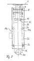
- Figure 1 shows a schematic representation of a first Transport carriage 2, which is part of a rotating chain of Transport carriage of a not shown here Sorting conveyor is.
- a funding direction of Sorting conveyor runs perpendicular to the display plane.
- the trolley 2 has one on a support unit 4, 4 'mounted storage tray 6, 6' for receiving from here General cargo parts not shown.
- the support unit 4, 4 ' is about an axis running parallel to the conveying direction 8 pivoted and in the figure in to the right drawn tilted position.
- the support unit 4 with cam-shaped pins 10, 10 ' only with the deflection in a circular arc Guideway 12 guided, which in a base module 14th is molded.
- the base module 14 is thus also used for carrying the support unit 4 and does not connect to here drive elements of the sorting conveyor further shown, e.g. Linear motors, and the neighboring transport car.
- lever arm 6 ' In order to tilt a storage tray 6, 6 'on one side, it is provided that on the each other arranged lever arm, here the Lever arm 6 ', in a setting 28, 28' to control the present embodiment is only two-dimensional curved curve in space specifies that the lever arm 16 'to has to follow. To guide the lever arm 16 'in the backdrop 28, 28 ', the lever arms 16, 16' have a friction bearing Cam follower roller 30, 30 ', which is not by means of a here further illustrated control element in the backdrop 28, 28 ' is controlled.
- the lock is that the Roll-mounted pin 26 'in a side of the guideway 22 located first bulge 32, which is part of the Guide track 22 is stored in the park position and by means of a deflection roller 34 in a first pivoting direction 36 is pivoted.
- the deflection roller 34 would also be dispensable because the function of the deflection roller 34 at accordingly designed control element also by attacking the Cam follower roller can be achieved directly.
- the first Swivel direction 36 is substantially perpendicular to Lift movement 18 oriented. The first swivel movement takes place around the axis of the pin 24 '.
- the lifting movement 18 then follows with the tilting of the Carrying unit 4 'and the tray 6'. In this status is the tilting movement shown.
- To lock the a tilted position is followed by a movement into a second pivot direction 38 anti-parallel to the first Swivel direction 36.
- the roller-bearing pin 26 'then rests in a second bulge 40 laterally at the end of the vertical ascending section of the guideway 22 and can not more directly down or up. So that is ensures that the tray 6 'permanently in the tilted position remains until the trolley 2 one Reset scenery not shown here happens and achieved a reverse sequence of movements of the lever arm 16 ' is.
- FIG. 2 shows a side view of the transport carriage 2. This view makes it particularly clear that the Base module 14 has two mirror images of one another Parts 14a, 14b includes. In this way, the Support unit 4 and the lever arms 16 particularly well in the inner guideways 12, 20, 22 out.
- FIG 3 shows a second transport carriage 42 one here sorting conveyor, not shown, in which also a support unit 46 carrying a tray 44 is provided which is rotatably mounted about an axis 48.
- the support unit 46 and lever arms 50, 50 'are in turn held a base module 54.
- the upper one serves Bulge 62 of locking the home position of the Storage tray 44.
- Lower bulge 60 serves accordingly locking the tilted position as shown in Figure 4 is shown.
- the lever arms 50, 50 ' also have cam-shaped pins 64, 66, by means of which the guide in the Guideways 56, 58 is achieved.
- Figure 5 shows a third transport carriage 68, in which Contrast to the previous embodiments two-part lever arm 70 with a modified Functional mechanism is used.
- the rest Functional mechanisms correspond to those of the two principles explained previous embodiments.
- the lever arm 70 has an enveloping body 72 and a Swivel rod 74.
- the enveloping body 72 picks up Sliding seat on a support unit 76 'for the storage tray 6, 6' on and is essentially only movable in the stroke direction 18.
- the Swivel rod 74 is arranged in the envelope 72.
- the upper end facing the support unit 76 is in one Bearing 79 rotatably connected to the casing 72; the opposite lower end with the cam follower roller 30 controllable in the backdrop 28, 28 '.
- the tilting and locking movement of the tray 6, 6 'is in present embodiment achieved by the lower End of the pivot rod 74 to release the locked Basic position within the dimensions of the enveloping body 72 in the first pivot direction 36 is pivoted.
- the roller-mounted pin 26, 26 'is pivoted out a first one laterally extending vertically Guide path 78 located bulge 80 and moved out is then used to achieve the tilting movement in Lifting direction 18 has been moved together with the enveloping element 72.
- To lock the tilted end position is the Swivel rod 74 in the second swivel direction 38, the is oriented antiparallel to the first pivoting direction 36, in a second bulge 82 has been pivoted.
- a special feature of this embodiment is that the achievable tilt angle is variable within certain limits is adjustable.
- one has the enveloping body 72 and the Support unit 76 leading base module 84 and the pivot rod 74 corresponding cams 86 and receptacles 88 for the cams 86, the cams 86 and Recordings 88 lying one behind the other in the stroke direction 18 are arranged.
- a stop 90 to limit the tilting movement for the Support unit 76 provided.
- This stop 90 is present realized as an insert, which in the guideway 12th can be inserted, in which the support unit 76 with its pin 10 is performed.
- the stop 90 can also be used for the Envelope body 72 is provided to limit its stroke movement 18 his. This would also have the advantage that an adjustment of the maximum tilt angle with a height adjustable configured stop 90 can be made from the outside could.
- Another alternative is to the tray against a stop in the course of the tilting movement to come across. The position of this stop itself, for example, using a backdrop can be set. This allows within one Sorting conveyor with one and the same transport trolley different tilt angles that can be adapted to current needs will be realized.
Landscapes
- Engineering & Computer Science (AREA)
- Mechanical Engineering (AREA)
- Discharge Of Articles From Conveyors (AREA)
Priority Applications (5)
| Application Number | Priority Date | Filing Date | Title |
|---|---|---|---|
| EP00125653A EP1209105A1 (fr) | 2000-11-23 | 2000-11-23 | Convoyeur de triage avec module de base |
| EP01982332A EP1335871A1 (fr) | 2000-11-23 | 2001-09-21 | Convoyeur de triage avec module de base |
| PCT/EP2001/010923 WO2002042185A1 (fr) | 2000-11-23 | 2001-09-21 | Convoyeur de triage avec module de base |
| AU2002213944A AU2002213944A1 (en) | 2000-11-23 | 2001-09-21 | Sorting conveyor with base module |
| US10/426,869 US20030183482A1 (en) | 2000-11-23 | 2003-05-01 | Sorting conveyor with base module |
Applications Claiming Priority (1)
| Application Number | Priority Date | Filing Date | Title |
|---|---|---|---|
| EP00125653A EP1209105A1 (fr) | 2000-11-23 | 2000-11-23 | Convoyeur de triage avec module de base |
Publications (1)
| Publication Number | Publication Date |
|---|---|
| EP1209105A1 true EP1209105A1 (fr) | 2002-05-29 |
Family
ID=8170459
Family Applications (2)
| Application Number | Title | Priority Date | Filing Date |
|---|---|---|---|
| EP00125653A Withdrawn EP1209105A1 (fr) | 2000-11-23 | 2000-11-23 | Convoyeur de triage avec module de base |
| EP01982332A Withdrawn EP1335871A1 (fr) | 2000-11-23 | 2001-09-21 | Convoyeur de triage avec module de base |
Family Applications After (1)
| Application Number | Title | Priority Date | Filing Date |
|---|---|---|---|
| EP01982332A Withdrawn EP1335871A1 (fr) | 2000-11-23 | 2001-09-21 | Convoyeur de triage avec module de base |
Country Status (4)
| Country | Link |
|---|---|
| US (1) | US20030183482A1 (fr) |
| EP (2) | EP1209105A1 (fr) |
| AU (1) | AU2002213944A1 (fr) |
| WO (1) | WO2002042185A1 (fr) |
Cited By (3)
| Publication number | Priority date | Publication date | Assignee | Title |
|---|---|---|---|---|
| EP1447359A3 (fr) * | 2003-02-14 | 2004-11-03 | Vanderlande Industries Nederland B.V. | Convoyeur de triage à plateaux basculants et procédé correspondant de tri de produits |
| CN102502229A (zh) * | 2011-11-02 | 2012-06-20 | 丹阳市富豪机械制造有限公司 | 输送线送料小车自动卸料及复位装置 |
| CN110316521A (zh) * | 2018-03-29 | 2019-10-11 | 南京高灵彩印厂 | 一种彩印包装材料运输装置 |
Families Citing this family (8)
| Publication number | Priority date | Publication date | Assignee | Title |
|---|---|---|---|---|
| NZ523931A (en) * | 2003-01-31 | 2005-06-24 | Anzpac Systems Ltd | Article carrier for a grading apparatus |
| CN107117087A (zh) * | 2017-05-23 | 2017-09-01 | 北京京东尚科信息技术有限公司 | 分拣型自动导引运输车 |
| US10450142B1 (en) * | 2018-04-26 | 2019-10-22 | Intelligrated Headquarters, Llc | Conveyor carrier cart |
| US10663048B2 (en) * | 2018-08-07 | 2020-05-26 | GBI, Intralogistics Solutions | Tilt tray mechanism |
| US11851218B1 (en) * | 2019-09-23 | 2023-12-26 | Amazon Technologies, Inc. | Material handling apparatus |
| US12077395B2 (en) * | 2020-02-19 | 2024-09-03 | Aquabot Ltd. | Cart with tilt mechanism |
| DE102022100782A1 (de) | 2022-01-14 | 2023-07-20 | Böwe Systec Gmbh | Fahrbarer Transportbehälter für eine Sortiervorrichtung und Verfahren zum Öffnen und/oder Schließen eines Transportbehälters |
| CN114798510B (zh) * | 2022-05-30 | 2023-09-01 | 镇江新宇固体废物处置有限公司 | 一种用于医疗废物的半封闭型负压物料输送线 |
Citations (5)
| Publication number | Priority date | Publication date | Assignee | Title |
|---|---|---|---|---|
| WO1990009944A1 (fr) * | 1989-02-24 | 1990-09-07 | Kosan Crisplant A/S | Transporteur trieur |
| EP0556159A2 (fr) * | 1992-02-10 | 1993-08-18 | Grapha-Holding Ag | Installation de tri de colis |
| WO1998034859A1 (fr) * | 1997-02-07 | 1998-08-13 | Siemens Aktiengesellschaft | Systeme convoyeur pour le transport automatique d'articles |
| US5857555A (en) * | 1995-02-10 | 1999-01-12 | Grapha-Holding Ag | Actuating device for tilting a structural component |
| US6112879A (en) * | 1996-04-15 | 2000-09-05 | Mantissa Corporation | Tilting cart for a package sorting conveyor |
Family Cites Families (8)
| Publication number | Priority date | Publication date | Assignee | Title |
|---|---|---|---|---|
| US3167192A (en) * | 1961-01-10 | 1965-01-26 | Prospect Mfg Co Inc | Automatic sortation system |
| US4174773A (en) * | 1977-07-19 | 1979-11-20 | A-T-O Inc. | Sortation conveyor tip-up and mounting apparatus |
| DK397584D0 (da) * | 1984-08-20 | 1984-08-20 | Cosan Crisplant As | Sorteringtransportoer med sidevippelige transportbakker |
| US4787498A (en) * | 1988-02-10 | 1988-11-29 | Babcock Industries Inc. | Tire handling tray sortation system |
| CA1316139C (fr) * | 1988-10-31 | 1993-04-13 | Karl Hartlepp | Materiel de tri |
| CH687617A5 (de) * | 1994-06-08 | 1997-01-15 | Grapha Holding Ag | Betaetigungsvorrichtung zum Kippen eines Bauteils. |
| CH688719A5 (de) * | 1994-11-16 | 1998-01-30 | Grapha Holding Ag Patentwesen | Verteilförderer für Stückgut. |
| DE19755474C1 (de) * | 1997-12-02 | 1999-02-11 | Mannesmann Ag | Förderer für die Sortierung von Stückgut |
-
2000
- 2000-11-23 EP EP00125653A patent/EP1209105A1/fr not_active Withdrawn
-
2001
- 2001-09-21 AU AU2002213944A patent/AU2002213944A1/en not_active Abandoned
- 2001-09-21 WO PCT/EP2001/010923 patent/WO2002042185A1/fr not_active Ceased
- 2001-09-21 EP EP01982332A patent/EP1335871A1/fr not_active Withdrawn
-
2003
- 2003-05-01 US US10/426,869 patent/US20030183482A1/en not_active Abandoned
Patent Citations (5)
| Publication number | Priority date | Publication date | Assignee | Title |
|---|---|---|---|---|
| WO1990009944A1 (fr) * | 1989-02-24 | 1990-09-07 | Kosan Crisplant A/S | Transporteur trieur |
| EP0556159A2 (fr) * | 1992-02-10 | 1993-08-18 | Grapha-Holding Ag | Installation de tri de colis |
| US5857555A (en) * | 1995-02-10 | 1999-01-12 | Grapha-Holding Ag | Actuating device for tilting a structural component |
| US6112879A (en) * | 1996-04-15 | 2000-09-05 | Mantissa Corporation | Tilting cart for a package sorting conveyor |
| WO1998034859A1 (fr) * | 1997-02-07 | 1998-08-13 | Siemens Aktiengesellschaft | Systeme convoyeur pour le transport automatique d'articles |
Cited By (3)
| Publication number | Priority date | Publication date | Assignee | Title |
|---|---|---|---|---|
| EP1447359A3 (fr) * | 2003-02-14 | 2004-11-03 | Vanderlande Industries Nederland B.V. | Convoyeur de triage à plateaux basculants et procédé correspondant de tri de produits |
| CN102502229A (zh) * | 2011-11-02 | 2012-06-20 | 丹阳市富豪机械制造有限公司 | 输送线送料小车自动卸料及复位装置 |
| CN110316521A (zh) * | 2018-03-29 | 2019-10-11 | 南京高灵彩印厂 | 一种彩印包装材料运输装置 |
Also Published As
| Publication number | Publication date |
|---|---|
| WO2002042185A1 (fr) | 2002-05-30 |
| EP1335871A1 (fr) | 2003-08-20 |
| AU2002213944A1 (en) | 2002-06-03 |
| US20030183482A1 (en) | 2003-10-02 |
Similar Documents
| Publication | Publication Date | Title |
|---|---|---|
| EP3774601B1 (fr) | Poste de déchargement et procédé destiné au déchargement d'un récipient de produit à transporter chargé avec un produit à transporter | |
| DE4090308C5 (de) | Sortierförderer | |
| DE2151439C2 (de) | Endlosförderanlage für Pakete | |
| DE3906857C2 (de) | Transporteinrichtung mit L-förmigem Hänger | |
| EP2998249B1 (fr) | Dispositif de convoyage pour le convoyage d'objets | |
| EP3922586A1 (fr) | Récipient pour produit à transporter et dispositif de transport suspendu associé | |
| EP0856480B1 (fr) | Moyen de transport guidé sur rails et système de transport avec un tel moyen de transport | |
| DE2714884A1 (de) | Foerdersystem | |
| EP3615458B1 (fr) | Dispositif de transfert | |
| EP1209105A1 (fr) | Convoyeur de triage avec module de base | |
| EP0686586B1 (fr) | Dispositif d'actionnement pour basculer un élément de construction | |
| DE1431736B2 (de) | Umlauffoerderer mit in horizontaler bahn umlaufenden foerdereinheiten mit kippbaren lasttraegern | |
| DE102020121883A1 (de) | Fahrzeug mit Ladegutaufnahme | |
| DE19532641C2 (de) | Ziehvorrichtung für Behälter mit Ziehnuten, insbesondere für die Anordnung auf dem Hubtisch eines Regalbediengerätes | |
| EP3113124B1 (fr) | Dispositif de levage, automate de marchandise | |
| DE3141769A1 (de) | Ladehilfe fuer fahrzeuge | |
| DE19922343C2 (de) | Hängeförderanlage mit Lasthaken zum Aufnehmen mehrerer Objekte | |
| DE19920386C2 (de) | Lager für eine umklappbare Rückenlehne | |
| EP0859716A1 (fr) | Systeme convoyeur sur rail et procede permettant de le faire fonctionner | |
| EP0537421A1 (fr) | Installation de convoyeur de triage | |
| EP0431141A1 (fr) | Chariot d'entreposage et de transfert de porteurs de marchandises. | |
| DE60105304T2 (de) | Einstellbarer förderer, förderverfahren und bestrahlungsvorrichtung | |
| DE4042709C2 (de) | Sortierförderer | |
| DE19620635C2 (de) | Kippschalenanordnung für Sortierförderanlagen | |
| DE1905406C2 (de) | Verschiebeeinrichtung zur automatischen Be- und Entladung eines Aufzuges |
Legal Events
| Date | Code | Title | Description |
|---|---|---|---|
| PUAI | Public reference made under article 153(3) epc to a published international application that has entered the european phase |
Free format text: ORIGINAL CODE: 0009012 |
|
| AK | Designated contracting states |
Kind code of ref document: A1 Designated state(s): AT BE CH CY DE DK ES FI FR GB GR IE IT LI LU MC NL PT SE TR |
|
| AX | Request for extension of the european patent |
Free format text: AL;LT;LV;MK;RO;SI |
|
| AKX | Designation fees paid | ||
| REG | Reference to a national code |
Ref country code: DE Ref legal event code: 8566 |
|
| STAA | Information on the status of an ep patent application or granted ep patent |
Free format text: STATUS: THE APPLICATION IS DEEMED TO BE WITHDRAWN |
|
| 18D | Application deemed to be withdrawn |
Effective date: 20021130 |