EP0525268A1 - Tirant pour dispositif d'arrêt de porte de type frottant et dispositif d'arrêt de porte comportant ce tirant - Google Patents
Tirant pour dispositif d'arrêt de porte de type frottant et dispositif d'arrêt de porte comportant ce tirant Download PDFInfo
- Publication number
- EP0525268A1 EP0525268A1 EP91402754A EP91402754A EP0525268A1 EP 0525268 A1 EP0525268 A1 EP 0525268A1 EP 91402754 A EP91402754 A EP 91402754A EP 91402754 A EP91402754 A EP 91402754A EP 0525268 A1 EP0525268 A1 EP 0525268A1
- Authority
- EP
- European Patent Office
- Prior art keywords
- tie rod
- masses
- sectors
- faces
- arm
- Prior art date
- Legal status (The legal status is an assumption and is not a legal conclusion. Google has not performed a legal analysis and makes no representation as to the accuracy of the status listed.)
- Granted
Links
- 239000002184 metal Substances 0.000 claims abstract description 7
- 239000002861 polymer material Substances 0.000 claims abstract description 4
- 239000011248 coating agent Substances 0.000 claims description 7
- 238000000576 coating method Methods 0.000 claims description 7
- 239000000463 material Substances 0.000 claims description 4
- 239000004952 Polyamide Substances 0.000 claims description 2
- 210000003041 ligament Anatomy 0.000 claims description 2
- 229920002647 polyamide Polymers 0.000 claims description 2
- 229920001971 elastomer Polymers 0.000 claims 1
- 239000000806 elastomer Substances 0.000 claims 1
- 239000013536 elastomeric material Substances 0.000 abstract description 2
- 230000007797 corrosion Effects 0.000 description 2
- 238000005260 corrosion Methods 0.000 description 2
- 238000010586 diagram Methods 0.000 description 2
- 229910000831 Steel Inorganic materials 0.000 description 1
- 238000002513 implantation Methods 0.000 description 1
- 238000009434 installation Methods 0.000 description 1
- 239000011253 protective coating Substances 0.000 description 1
- 230000002787 reinforcement Effects 0.000 description 1
- 239000010959 steel Substances 0.000 description 1
Images
Classifications
-
- E—FIXED CONSTRUCTIONS
- E05—LOCKS; KEYS; WINDOW OR DOOR FITTINGS; SAFES
- E05C—BOLTS OR FASTENING DEVICES FOR WINGS, SPECIALLY FOR DOORS OR WINDOWS
- E05C17/00—Devices for holding wings open; Devices for limiting opening of wings or for holding wings open by a movable member extending between frame and wing; Braking devices, stops or buffers, combined therewith
- E05C17/02—Devices for holding wings open; Devices for limiting opening of wings or for holding wings open by a movable member extending between frame and wing; Braking devices, stops or buffers, combined therewith by mechanical means
- E05C17/04—Devices for holding wings open; Devices for limiting opening of wings or for holding wings open by a movable member extending between frame and wing; Braking devices, stops or buffers, combined therewith by mechanical means with a movable bar or equivalent member extending between frame and wing
- E05C17/12—Devices for holding wings open; Devices for limiting opening of wings or for holding wings open by a movable member extending between frame and wing; Braking devices, stops or buffers, combined therewith by mechanical means with a movable bar or equivalent member extending between frame and wing consisting of a single rod
- E05C17/20—Devices for holding wings open; Devices for limiting opening of wings or for holding wings open by a movable member extending between frame and wing; Braking devices, stops or buffers, combined therewith by mechanical means with a movable bar or equivalent member extending between frame and wing consisting of a single rod sliding through a guide
- E05C17/203—Devices for holding wings open; Devices for limiting opening of wings or for holding wings open by a movable member extending between frame and wing; Braking devices, stops or buffers, combined therewith by mechanical means with a movable bar or equivalent member extending between frame and wing consisting of a single rod sliding through a guide concealed, e.g. for vehicles
- E05C17/206—Devices for holding wings open; Devices for limiting opening of wings or for holding wings open by a movable member extending between frame and wing; Braking devices, stops or buffers, combined therewith by mechanical means with a movable bar or equivalent member extending between frame and wing consisting of a single rod sliding through a guide concealed, e.g. for vehicles with elastomeric springs to hold wing open
Definitions
- the invention relates to a tie rod for a friction-type door stop device, in particular for a vehicle door and to door stop devices comprising such a tie rod.
- Friction type door stop devices which essentially consist of a tie rod, one end of which is capable of being hinged to the door and the other end of which is free, and of a housing fixed to the frame of the door. , which contains friction bodies arranged in the housing on either side of a passage which passes through the housing and into which the tie rod can slide, these friction bodies being pressed against the tie rod by elastic means, and the tie rod having lateral bosses which, in cooperation with the friction bodies, determine stop positions of the tie rod and, consequently, stop positions of the door.
- a tie rod one end of which is capable of being hinged to the door and the other end of which is free
- Friction bodies arranged in the housing on either side of a passage which passes through the housing and into which the tie rod can slide, these friction bodies being pressed against the tie rod by elastic means, and the tie rod having lateral bosses which, in cooperation with the friction bodies, determine stop positions of the tie rod and, consequently, stop positions of the door.
- the object of the present invention is to improve such a device, in particular to make it less noisy, less sensitive to wear and such that wear does not constitute a risk of corrosion.
- the tie rod consists of a metal insert covered with a coating of polymer material whose thickness is variable so that said bosses are formed by variations in thickness of the coating.
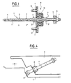
- the door stop device shown in Figures 1 to 3 consists of a tie rod T and a housing B.
- the tie rod T consists of a longitudinal steel plate 1 of constant thickness, the two large opposite faces 2,2 ′ are covered with a coating of polymer material, preferably of a polyamide material.
- the thickness of the coating is variable; this thickness variation determines notches 3.3 ′ distributed over the length of the tie rod, in a manner known per se.
- the short sides of the tie rod are preferably also coated with the polymeric material.
- the tie rod has an orifice 4 for mounting on the frame of a door (or on the door) and, at its other end, the tie rod comprises a stop assembly consisting for example of an elastic damper 5 and metal reinforcement 6 which are threaded onto the tie rod and held by a key 7 passing through an orifice 8 of the tie rod.
- the housing B consists of a bottom 9 and a cover 10 which has orifices 11 cooperating for the passage of screws 12 serving to fix the housing to the door (or to the door frame).
- the bottom and the cover cooperate to determine an internal chamber and are provided with two vis-à-vis openings 13,14 able to let pass the tie rod which can thus pass through the chamber.
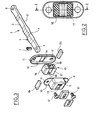
- a body 15 of elastomeric material consisting of two masses of generally parallelepipedal shape 16,17 facing each other joined by ligaments 18 which determine between them and between the two masses sufficient space to accommodate two sectors 19.20 and to allow the tie rod T introduced in the slots 13.14 to pass between the sectors.
- the volume and the conformation of the chamber are studied in relation to the conformation of the masses 16,17 and the sectors 19,20 so that the sectors are permanently applied with pressure against the large faces of the tie rod and that the body 15 can deform elastically in the passage of the tie rod bosses without ever being compressed in the housing.
- the masses 16, 17 have a rectangular or square base and a trunk-pyramidal apex and the faces of the sectors which are in contact with the tie have convex shapes adapted to the profile of the tie.
- the faces of the masses which are parallel to the direction of sliding of the tie rod preferably comprise recessed parts and raised parts (for example ridges).
- the bosses of the tie rod have slopes whose inclinations are chosen different according to the desired friction forces.
- the tie rod moves in the housing between the two sectors.
- the two sectors in permanent contact with the tie rod, undergo the variations in thickness of the tie rod (bosses) compressing the elastomeric masses against the housing. The greatest efforts take place during the passage of the bosses against the sectors.
- the wear between the sectors and the tie rod is mainly suffered by the tie rod.
- the metal parts of the case (case-cover and sectors) do not undergo corrosion because the case and the cover do not undergo any friction, therefore keep their protective coating, and the sectors are not worn by the tie rod. Due to the absence of metal-to-metal contact, the device does not generate any operating noise.
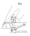
- FIG. 5 illustrates the operation (in itself known) of the device which makes it possible to maintain the door in the closed position (1), in the medium open position (II) and in the maximum open position (III).
Landscapes
- Engineering & Computer Science (AREA)
- Mechanical Engineering (AREA)
- Lock And Its Accessories (AREA)
- Spinning Or Twisting Of Yarns (AREA)
- Special Wing (AREA)
- Closing And Opening Devices For Wings, And Checks For Wings (AREA)
- Power-Operated Mechanisms For Wings (AREA)
Abstract
Description
- L'invention concerne un tirant pour dispositif d'arrêt de porte de type frottant, notamment pour une porte de véhicule et les dispositifs d'arrêt de porte comportant un tel tirant.
- On connaît des dispositifs d'arrêt de porte de type frottant essentiellement constitués d'un tirant dont une extrémité est apte à être articulée à la porte et dont l'autre extrémité est libre, et d'un boîtier, fixé au bâti de la porte, qui contient des corps de friction disposés dans le boîtier de part et d'autre d'un passage qui traverse le boîtier et dans lequel peut glisser le tirant, ces corps de friction étant pressés contre le tirant par des moyens élastiques, et le tirant présentant des bossages latéraux qui, en coopérant avec les corps de friction, déterminent des positions d'arrêt du tirant et, par conséquent, des positions d'arrêt de la porte. Un tel dispositif est décrit par exemple dans le brevet français 1 143 995.
- La présente invention a pour objet d'améliorer un tel dispositif, notamment pour le rendre moins bruyant, moins sensible à l'usure et tel que l'usure ne constitue pas un risque de corrosion.
- Selon la caractéristique fondamentale de l'invention, le tirant est constitué d'un insert métallique recouvert d'un revêtement en matière polymère dont l'épaisseur est variable en sorte que lesdits bossages soient constitués par les variations d'épaisseur du revêtement.
- On décrira ci-après un exemple d'un dispositif d'arrêt de porte conforme à l'invention, en référence aux figures du dessin joint, et la description et les figures feront apparaître d'autres particularités de l'invention.
- Sur les figures :
- - la figure 1 est une coupe longitudinale du dispositif selon le plan I-I de la figure 2 ;
- - la figure 2 est une coupe suivant le plan II-II de la figure 1 ;
- - la figure 3 est une perspective éclatée du dispositif ;
- - la figure 4 est un schéma d'un exemple d'implantation du dispositif, et
- - la figure 5 est un schéma montrant différentes positions du tirant au cours du fonctionnement du dispositif.
- Le dispositif d'arrêt de porte représenté sur les figures 1 à 3 est constitué d'un tirant T et d'un boîtier B.
- Le tirant T est constitué d'un plat longitudinal en acier 1 d'épaisseur constante dont les deux grandes faces opposées 2,2' sont recouvertes d'un revêtement en matière polymère, de préférence en une matière polyamide. L'épaisseur du revêtement est variable ; cette variation d'épaisseur détermine des crans 3,3' répartis sur la longueur du tirant, de façon connue en soi. Les petits côtés du tirant sont de préférence également enrobés de la matière polymère.
- A une extrémité, le tirant comporte un orifice 4 pour son montage sur le bâti d'une porte (ou sur la porte) et, à son autre extrémité, le tirant comporte un ensemble de butée constitué par exemple d'un amortisseur élastique 5 et renfort métallique 6 qui sont enfilés sur le tirant et maintenus par une clavette 7 passant dans un orifice 8 du tirant.
- Le boîtier B est constitué d'un fond 9 et d'un couvercle 10 qui comporte des orifices 11 coopérant pour le passage de vis 12 servant à fixer le boîtier à la porte (ou au bâti de la porte). Le fond et le couvercle coopèrent pour déterminer une chambre interne et sont munis de deux lumières en vis-à-vis 13,14 aptes à laisser passer le tirant qui peut ainsi traverser la chambre.
- Dans la chambre, est contenu un corps 15 en matière élastomère constitué de deux masses de forme générale parallélépipédique 16,17 en vis-à-vis réunies par des ligaments 18 qui déterminent entre eux et entre les deux masses un espace suffisant pour loger deux secteurs métalliques 19,20 et pour laisser passer entre les secteurs le tirant T introduit dans les lumières 13,14.
- Le volume et la conformation de la chambre sont étudiés en rapport avec la conformation des masses 16,17 et des secteurs 19,20 pour que les secteurs soient en permanence appliqués avec pression contre les grandes faces du tirant et que le corps 15 puisse se déformer élastiquement au passage des bossages du tirant sans être jamais comprimé dans le boîtier.
- Dans une solution préférée, les masses 16,17 ont une base rectangulaire ou carrée et un sommet tronc-pyramidal et les faces des secteurs qui sont au contact du tirant ont des formes convexes adaptées au profil du tirant.
- Les faces des masses qui sont parallèles au sens de glissement du tirant comportent de préférence des parties en creux et des parties en relief (par exemple des stries).
- Les bossages du tirant ont des pentes dont les inclinaisons sont choisies différentes selon les efforts de frottement souhaités.
- Durant l'ouverture ou la fermeture de la porte, le tirant se déplace dans le boîtier entre les deux secteurs. Les deux secteurs, en contact permanent avec le tirant, subissent les variations d'épaisseurs du tirant (bossages) comprimant les masses élastomères contre le boîtier. Les efforts les plus importants ont lieu lors du passage des bossages contre les secteurs.
- L'usure entre les secteurs et le tirant est subie essentiellement par le tirant. Les pièces métalliques du boîtier (boîtier-couvercle et secteurs) ne subissent pas de corrosion car le boîtier et le couvercle ne subissent aucun frottement, donc conservent leur revêtement de protection, et les secteurs ne sont pas usés par le tirant. Du fait de l'absence de contact métal-métal, le dispositif ne génère aucun bruit de fonctionnement.
- La figure 5 illustre le fonctionnement (en soi connu) du dispositif qui permet de maintenir la porte en position fermée (1), en position d'ouverture moyenne (II) et en position d'ouverture maximale (III).
Claims (6)
Applications Claiming Priority (2)
| Application Number | Priority Date | Filing Date | Title |
|---|---|---|---|
| FR9108882 | 1991-07-15 | ||
| FR9108882A FR2679287B1 (fr) | 1991-07-15 | 1991-07-15 | Tirant pour dispositif d'arret de porte de type frottant et dispositif d'arret de porte comportant ce tirant. |
Publications (2)
| Publication Number | Publication Date |
|---|---|
| EP0525268A1 true EP0525268A1 (fr) | 1993-02-03 |
| EP0525268B1 EP0525268B1 (fr) | 1995-06-14 |
Family
ID=9415090
Family Applications (1)
| Application Number | Title | Priority Date | Filing Date |
|---|---|---|---|
| EP91402754A Expired - Lifetime EP0525268B1 (fr) | 1991-07-15 | 1991-10-15 | Tirant pour dispositif d'arrêt de porte de type frottant et dispositif d'arrêt de porte comportant ce tirant |
Country Status (5)
| Country | Link |
|---|---|
| EP (1) | EP0525268B1 (fr) |
| AT (1) | ATE123840T1 (fr) |
| DE (1) | DE69110461T2 (fr) |
| ES (1) | ES2074242T3 (fr) |
| FR (1) | FR2679287B1 (fr) |
Cited By (7)
| Publication number | Priority date | Publication date | Assignee | Title |
|---|---|---|---|---|
| GB2266338A (en) * | 1992-03-21 | 1993-10-27 | Ihw Eng Ltd | Door check mechanism |
| EP0805251A3 (fr) * | 1996-04-05 | 1999-08-11 | FRIEDR. FINGSCHEIDT GmbH | Arrêt de porte pour véhicule |
| EP0959210A1 (fr) * | 1998-05-16 | 1999-11-24 | ISE Innomotive Systems Europe GmbH | Dispositif d'arrêt pour portes de véhicules |
| EP1146187A1 (fr) | 2000-04-14 | 2001-10-17 | Gammastamp S.p.A. | Dispositif d'arrêt de porte pour vehicules |
| US6687953B1 (en) | 2000-10-13 | 2004-02-10 | Ventra Group Inc. | Torsion spring door check device |
| EP2011940A1 (fr) * | 2007-07-02 | 2009-01-07 | Gammastamp S.p.A. | Dispositif d'arrêt de porte pour véhicules |
| EP2354395A1 (fr) | 2010-02-03 | 2011-08-10 | Gammastamp S.p.A. | Dispositif d'arrêt de porte pour véhicules |
Families Citing this family (4)
| Publication number | Priority date | Publication date | Assignee | Title |
|---|---|---|---|---|
| DE4207706B4 (de) * | 1992-03-11 | 2004-05-27 | ED. SCHARWäCHTER GMBH | Stufenloser Türfeststeller für Kraftwagentüren |
| FR2733533B1 (fr) * | 1995-04-27 | 1997-07-25 | Coutier Moulage Gen Ind | Arret de porte ou similaire, notamment pour vehicule automobile |
| DE102004016138A1 (de) * | 2004-04-01 | 2005-10-20 | Bayerische Motoren Werke Ag | Türfeststeller für ein Kraftfahrzeug |
| CN108442834A (zh) * | 2017-12-08 | 2018-08-24 | 丰业迪睦斯(芜湖)汽车部件有限公司 | 汽车限位器壳体结构 |
Citations (5)
| Publication number | Priority date | Publication date | Assignee | Title |
|---|---|---|---|---|
| US2321409A (en) * | 1937-05-17 | 1943-06-08 | Nat Stamping Company | Door check |
| FR1143995A (fr) * | 1956-03-22 | 1957-10-08 | Boyriven Sa | Tirant formant arrêt de porte pour automobiles |
| FR1414880A (fr) * | 1964-09-07 | 1965-10-22 | Cousin Freres Sa | Dispositif d'arrêt de porte en position ouverte applicable notamment aux portièresde véhicules automobiles |
| DE3515883A1 (de) * | 1985-05-03 | 1986-11-06 | Siegfried 5620 Velbert Klingenburg | Mit befestigungsflanschen versehener tuerfeststeller, insbesondere fuer kraftfahrzeugtueren |
| GB2229668A (en) * | 1989-03-28 | 1990-10-03 | Aisin Seiki | Moulding a lever |
-
1991
- 1991-07-15 FR FR9108882A patent/FR2679287B1/fr not_active Expired - Fee Related
- 1991-10-15 DE DE69110461T patent/DE69110461T2/de not_active Expired - Fee Related
- 1991-10-15 ES ES91402754T patent/ES2074242T3/es not_active Expired - Lifetime
- 1991-10-15 EP EP91402754A patent/EP0525268B1/fr not_active Expired - Lifetime
- 1991-10-15 AT AT91402754T patent/ATE123840T1/de not_active IP Right Cessation
Patent Citations (5)
| Publication number | Priority date | Publication date | Assignee | Title |
|---|---|---|---|---|
| US2321409A (en) * | 1937-05-17 | 1943-06-08 | Nat Stamping Company | Door check |
| FR1143995A (fr) * | 1956-03-22 | 1957-10-08 | Boyriven Sa | Tirant formant arrêt de porte pour automobiles |
| FR1414880A (fr) * | 1964-09-07 | 1965-10-22 | Cousin Freres Sa | Dispositif d'arrêt de porte en position ouverte applicable notamment aux portièresde véhicules automobiles |
| DE3515883A1 (de) * | 1985-05-03 | 1986-11-06 | Siegfried 5620 Velbert Klingenburg | Mit befestigungsflanschen versehener tuerfeststeller, insbesondere fuer kraftfahrzeugtueren |
| GB2229668A (en) * | 1989-03-28 | 1990-10-03 | Aisin Seiki | Moulding a lever |
Cited By (8)
| Publication number | Priority date | Publication date | Assignee | Title |
|---|---|---|---|---|
| GB2266338A (en) * | 1992-03-21 | 1993-10-27 | Ihw Eng Ltd | Door check mechanism |
| GB2266338B (en) * | 1992-03-21 | 1996-05-15 | Ihw Eng Ltd | Door check mechanism |
| EP0805251A3 (fr) * | 1996-04-05 | 1999-08-11 | FRIEDR. FINGSCHEIDT GmbH | Arrêt de porte pour véhicule |
| EP0959210A1 (fr) * | 1998-05-16 | 1999-11-24 | ISE Innomotive Systems Europe GmbH | Dispositif d'arrêt pour portes de véhicules |
| EP1146187A1 (fr) | 2000-04-14 | 2001-10-17 | Gammastamp S.p.A. | Dispositif d'arrêt de porte pour vehicules |
| US6687953B1 (en) | 2000-10-13 | 2004-02-10 | Ventra Group Inc. | Torsion spring door check device |
| EP2011940A1 (fr) * | 2007-07-02 | 2009-01-07 | Gammastamp S.p.A. | Dispositif d'arrêt de porte pour véhicules |
| EP2354395A1 (fr) | 2010-02-03 | 2011-08-10 | Gammastamp S.p.A. | Dispositif d'arrêt de porte pour véhicules |
Also Published As
| Publication number | Publication date |
|---|---|
| FR2679287B1 (fr) | 1995-11-10 |
| ES2074242T3 (es) | 1995-09-01 |
| EP0525268B1 (fr) | 1995-06-14 |
| ATE123840T1 (de) | 1995-06-15 |
| DE69110461D1 (de) | 1995-07-20 |
| FR2679287A1 (fr) | 1993-01-22 |
| DE69110461T2 (de) | 1996-02-08 |
Similar Documents
| Publication | Publication Date | Title |
|---|---|---|
| EP0525268A1 (fr) | Tirant pour dispositif d'arrêt de porte de type frottant et dispositif d'arrêt de porte comportant ce tirant | |
| JP2003118369A (ja) | 自動車用ドアチェッカ | |
| GB2060749A (en) | Sash balance foot seal mechanism | |
| US3019493A (en) | Weatherseal for doors | |
| BE831756A (fr) | Dispositif pour la limitation de l'angle d'ouverture du battant d'une fenetre ou d'une porte ou d'un organe analogue | |
| FR2666616A1 (fr) | Dispositif de retenue pour un element mobile pivotant, notamment pour une porte d'un vehicule. | |
| FR2664936A1 (fr) | Piece de menuiserie avec element de securite, du type porte ou fenetre. | |
| EP0867586B1 (fr) | Charnière pour portillon ou panneau pivotant, notamment pour panneau en verre | |
| EP2203618B1 (fr) | Dispositif d'ecartement d'un element ouvrant par rapport a un element fixe, notamment d'un vehicule automobile | |
| FR2696687A1 (fr) | Hublot pour véhicules de loisir. | |
| EP0801195A1 (fr) | Dispositif de fermeture à mécanisme à crémone pour portes et fenêtres coulissantes | |
| FR2626822A1 (fr) | Butee elastique notamment pour un element de carrosserie de vehicule automobile, et ouvrant de vehicule automobile equipe d'au moins une butee | |
| FR2653385A1 (fr) | Toit vitre relevable. | |
| EP3825159B1 (fr) | Rideau isotherme pour carrosserie frigorifique | |
| EP2956607A2 (fr) | Serrure de vehicule automobile | |
| JPS5838135Y2 (ja) | 自動車のドアチェック機構におけるチェック装置 | |
| FR2757807A1 (fr) | Dispositif d'obturation d'une ouverture radiale d'un rail de guidage | |
| FR2556035A1 (fr) | Dispositif de retenue de porte, notamment pour portes de vehicules automobiles | |
| FR2718625A1 (fr) | Double cale pour l'encadrement. | |
| FR2852622A1 (fr) | Agencement de pene dans une serrure pour portiere de vehicule automobile | |
| US1542813A (en) | Door buffer | |
| US909563A (en) | Door-check. | |
| JP4176223B2 (ja) | 自動車用ドアチェッカ | |
| FR2871186A1 (fr) | Dispositif de verrouillage pour porte, fenetre ou porte-fenetre coulissante | |
| BE701278A (fr) |
Legal Events
| Date | Code | Title | Description |
|---|---|---|---|
| PUAI | Public reference made under article 153(3) epc to a published international application that has entered the european phase |
Free format text: ORIGINAL CODE: 0009012 |
|
| AK | Designated contracting states |
Kind code of ref document: A1 Designated state(s): AT BE CH DE DK ES FR GB GR IT LI LU NL SE |
|
| 17P | Request for examination filed |
Effective date: 19930712 |
|
| 17Q | First examination report despatched |
Effective date: 19931018 |
|
| GRAA | (expected) grant |
Free format text: ORIGINAL CODE: 0009210 |
|
| AK | Designated contracting states |
Kind code of ref document: B1 Designated state(s): AT BE CH DE DK ES FR GB GR IT LI LU NL SE |
|
| PG25 | Lapsed in a contracting state [announced via postgrant information from national office to epo] |
Ref country code: NL Free format text: LAPSE BECAUSE OF NON-PAYMENT OF DUE FEES Effective date: 19950614 Ref country code: GR Free format text: LAPSE BECAUSE OF FAILURE TO SUBMIT A TRANSLATION OF THE DESCRIPTION OR TO PAY THE FEE WITHIN THE PRESCRIBED TIME-LIMIT Effective date: 19950614 Ref country code: DK Effective date: 19950614 Ref country code: AT Effective date: 19950614 |
|
| REF | Corresponds to: |
Ref document number: 123840 Country of ref document: AT Date of ref document: 19950615 Kind code of ref document: T |
|
| ITF | It: translation for a ep patent filed | ||
| REF | Corresponds to: |
Ref document number: 69110461 Country of ref document: DE Date of ref document: 19950720 |
|
| GBT | Gb: translation of ep patent filed (gb section 77(6)(a)/1977) |
Effective date: 19950710 |
|
| REG | Reference to a national code |
Ref country code: ES Ref legal event code: FG2A Ref document number: 2074242 Country of ref document: ES Kind code of ref document: T3 |
|
| PG25 | Lapsed in a contracting state [announced via postgrant information from national office to epo] |
Ref country code: SE Effective date: 19950914 |
|
| PG25 | Lapsed in a contracting state [announced via postgrant information from national office to epo] |
Ref country code: LU Free format text: LAPSE BECAUSE OF NON-PAYMENT OF DUE FEES Effective date: 19951031 Ref country code: LI Effective date: 19951031 Ref country code: CH Effective date: 19951031 |
|
| NLV1 | Nl: lapsed or annulled due to failure to fulfill the requirements of art. 29p and 29m of the patents act | ||
| PLBE | No opposition filed within time limit |
Free format text: ORIGINAL CODE: 0009261 |
|
| STAA | Information on the status of an ep patent application or granted ep patent |
Free format text: STATUS: NO OPPOSITION FILED WITHIN TIME LIMIT |
|
| 26N | No opposition filed | ||
| REG | Reference to a national code |
Ref country code: CH Ref legal event code: PL |
|
| PGFP | Annual fee paid to national office [announced via postgrant information from national office to epo] |
Ref country code: GB Payment date: 20001013 Year of fee payment: 10 |
|
| PGFP | Annual fee paid to national office [announced via postgrant information from national office to epo] |
Ref country code: ES Payment date: 20001023 Year of fee payment: 10 |
|
| PGFP | Annual fee paid to national office [announced via postgrant information from national office to epo] |
Ref country code: FR Payment date: 20001026 Year of fee payment: 10 |
|
| PGFP | Annual fee paid to national office [announced via postgrant information from national office to epo] |
Ref country code: DE Payment date: 20001114 Year of fee payment: 10 |
|
| PGFP | Annual fee paid to national office [announced via postgrant information from national office to epo] |
Ref country code: BE Payment date: 20001204 Year of fee payment: 10 |
|
| PG25 | Lapsed in a contracting state [announced via postgrant information from national office to epo] |
Ref country code: GB Free format text: LAPSE BECAUSE OF NON-PAYMENT OF DUE FEES Effective date: 20011015 |
|
| PG25 | Lapsed in a contracting state [announced via postgrant information from national office to epo] |
Ref country code: ES Free format text: LAPSE BECAUSE OF NON-PAYMENT OF DUE FEES Effective date: 20011016 |
|
| PG25 | Lapsed in a contracting state [announced via postgrant information from national office to epo] |
Ref country code: BE Free format text: LAPSE BECAUSE OF NON-PAYMENT OF DUE FEES Effective date: 20011031 |
|
| REG | Reference to a national code |
Ref country code: GB Ref legal event code: IF02 |
|
| BERE | Be: lapsed |
Owner name: SOC. FINANCIERE D' ETUDE ET DE DEVELOPPEMENT INDU Effective date: 20011031 |
|
| GBPC | Gb: european patent ceased through non-payment of renewal fee |
Effective date: 20011015 |
|
| PG25 | Lapsed in a contracting state [announced via postgrant information from national office to epo] |
Ref country code: FR Free format text: LAPSE BECAUSE OF NON-PAYMENT OF DUE FEES Effective date: 20020628 |
|
| PG25 | Lapsed in a contracting state [announced via postgrant information from national office to epo] |
Ref country code: DE Free format text: LAPSE BECAUSE OF NON-PAYMENT OF DUE FEES Effective date: 20020702 |
|
| REG | Reference to a national code |
Ref country code: FR Ref legal event code: ST |
|
| REG | Reference to a national code |
Ref country code: ES Ref legal event code: FD2A Effective date: 20021113 |
|
| PG25 | Lapsed in a contracting state [announced via postgrant information from national office to epo] |
Ref country code: IT Free format text: LAPSE BECAUSE OF NON-PAYMENT OF DUE FEES;WARNING: LAPSES OF ITALIAN PATENTS WITH EFFECTIVE DATE BEFORE 2007 MAY HAVE OCCURRED AT ANY TIME BEFORE 2007. THE CORRECT EFFECTIVE DATE MAY BE DIFFERENT FROM THE ONE RECORDED. Effective date: 20051015 |