EP0525340A1 - Procédé de contrôle d'un flash, et dispositif à flash, notamment une disposition d'un flash de studio - Google Patents
Procédé de contrôle d'un flash, et dispositif à flash, notamment une disposition d'un flash de studio Download PDFInfo
- Publication number
- EP0525340A1 EP0525340A1 EP92109747A EP92109747A EP0525340A1 EP 0525340 A1 EP0525340 A1 EP 0525340A1 EP 92109747 A EP92109747 A EP 92109747A EP 92109747 A EP92109747 A EP 92109747A EP 0525340 A1 EP0525340 A1 EP 0525340A1
- Authority
- EP
- European Patent Office
- Prior art keywords
- flash
- discharge
- unit according
- color temperature
- flash unit
- Prior art date
- Legal status (The legal status is an assumption and is not a legal conclusion. Google has not performed a legal analysis and makes no representation as to the accuracy of the status listed.)
- Granted
Links
- 238000000034 method Methods 0.000 title claims abstract description 26
- 239000003990 capacitor Substances 0.000 claims description 10
- 230000003111 delayed effect Effects 0.000 claims description 4
- 238000007599 discharging Methods 0.000 claims 1
- 230000000979 retarding effect Effects 0.000 claims 1
- 230000002123 temporal effect Effects 0.000 claims 1
- 229910052724 xenon Inorganic materials 0.000 description 5
- FHNFHKCVQCLJFQ-UHFFFAOYSA-N xenon atom Chemical compound [Xe] FHNFHKCVQCLJFQ-UHFFFAOYSA-N 0.000 description 5
- 238000001228 spectrum Methods 0.000 description 4
- 238000010586 diagram Methods 0.000 description 3
- 238000001914 filtration Methods 0.000 description 3
- 230000001105 regulatory effect Effects 0.000 description 3
- 230000001960 triggered effect Effects 0.000 description 3
- 238000000576 coating method Methods 0.000 description 2
- 230000001276 controlling effect Effects 0.000 description 2
- 230000000694 effects Effects 0.000 description 2
- 238000005516 engineering process Methods 0.000 description 2
- 239000000203 mixture Substances 0.000 description 2
- 230000032683 aging Effects 0.000 description 1
- 239000011248 coating agent Substances 0.000 description 1
- 238000010168 coupling process Methods 0.000 description 1
- 238000005859 coupling reaction Methods 0.000 description 1
- 238000013016 damping Methods 0.000 description 1
- 230000001934 delay Effects 0.000 description 1
- 230000001419 dependent effect Effects 0.000 description 1
- 238000011161 development Methods 0.000 description 1
- 230000018109 developmental process Effects 0.000 description 1
- 230000005611 electricity Effects 0.000 description 1
- 239000000839 emulsion Substances 0.000 description 1
- 230000035945 sensitivity Effects 0.000 description 1
- 239000004753 textile Substances 0.000 description 1
Images


Classifications
-
- G—PHYSICS
- G03—PHOTOGRAPHY; CINEMATOGRAPHY; ANALOGOUS TECHNIQUES USING WAVES OTHER THAN OPTICAL WAVES; ELECTROGRAPHY; HOLOGRAPHY
- G03B—APPARATUS OR ARRANGEMENTS FOR TAKING PHOTOGRAPHS OR FOR PROJECTING OR VIEWING THEM; APPARATUS OR ARRANGEMENTS EMPLOYING ANALOGOUS TECHNIQUES USING WAVES OTHER THAN OPTICAL WAVES; ACCESSORIES THEREFOR
- G03B15/00—Special procedures for taking photographs; Apparatus therefor
- G03B15/02—Illuminating scene
- G03B15/03—Combinations of cameras with lighting apparatus; Flash units
- G03B15/05—Combinations of cameras with electronic flash apparatus; Electronic flash units
-
- H—ELECTRICITY
- H05—ELECTRIC TECHNIQUES NOT OTHERWISE PROVIDED FOR
- H05B—ELECTRIC HEATING; ELECTRIC LIGHT SOURCES NOT OTHERWISE PROVIDED FOR; CIRCUIT ARRANGEMENTS FOR ELECTRIC LIGHT SOURCES, IN GENERAL
- H05B41/00—Circuit arrangements or apparatus for igniting or operating discharge lamps
- H05B41/14—Circuit arrangements
- H05B41/30—Circuit arrangements in which the lamp is fed by pulses, e.g. flash lamp
- H05B41/32—Circuit arrangements in which the lamp is fed by pulses, e.g. flash lamp for single flash operation
-
- G—PHYSICS
- G03—PHOTOGRAPHY; CINEMATOGRAPHY; ANALOGOUS TECHNIQUES USING WAVES OTHER THAN OPTICAL WAVES; ELECTROGRAPHY; HOLOGRAPHY
- G03B—APPARATUS OR ARRANGEMENTS FOR TAKING PHOTOGRAPHS OR FOR PROJECTING OR VIEWING THEM; APPARATUS OR ARRANGEMENTS EMPLOYING ANALOGOUS TECHNIQUES USING WAVES OTHER THAN OPTICAL WAVES; ACCESSORIES THEREFOR
- G03B2215/00—Special procedures for taking photographs; Apparatus therefor
- G03B2215/05—Combinations of cameras with electronic flash units
- G03B2215/0589—Diffusors, filters or refraction means
- G03B2215/0592—Diffusors, filters or refraction means installed in front of light emitter
Definitions
- the invention initially relates to a method for controlling a flash unit, in particular a studio flash system formed from flash heads controlled by a flash generator.
- flash devices in the form of studio flash systems are often used.
- Such flash systems generally consist of a plurality of so-called flash heads and a flash generator to which the flash heads are connected.
- the xenon gas flash tubes contained in the flash heads emit flash light with a color temperature with an average value of around 5,500 ° K.
- the color temperature of such flash tubes depends on various factors; on the one hand, such flash tubes are usually provided with a coating which is intended, for example, to prevent UV components in the flash. Coatings can change color with age, so that there may be deviations from the originally defined color temperature values.
- the flash tubes are usually used in conjunction with so-called light diffusers. Light diffusers can be designed differently, for example in the form of textile screens or the like. Depending on their age, these diffusers also yellow and thus also influence the color temperature.
- So-called automatic flash units are known as a further prior art. These devices automatically measure the brightness of the object during the flash and switch off the flash as soon as the light output of the flash is sufficient for the set or existing photographic parameters aperture and film sensitivity.
- the inevitable long-wave (red) flash pulse end area is cut off compared to the relatively short-wave (blue) flash pulse start, so that the average color temperature of the controlled flash shifts more towards the blue area, which can also lead to a color distortion compared to the unregulated normal discharge.
- the light from the flash source for exposing the film is matched as closely as possible to the emulsion of a color film.
- This adjustment is expressed by adjusting the color temperature index. If the adjustment is not taken into account, this leads to a color cast of the images, which must be corrected by filtering.
- the coordination and filtering effort for several light sources is usually so great that it can hardly be mastered by the photographer. As a rule, therefore, you do not make any precise adjustments and as a result accept color casts in parts of the image that sometimes have a very unsightly effect.
- a flash device for generating flash light of a given color temperature in which the desired color temperature can be set by suitable choice of the charging voltage and the flash duration for a given amount of light.
- the color temperature can only be really varied in the lower performance range; the possibility of changing the color temperature is extremely limited in the upper performance range.
- EP 9 969 604 further relates to an electronic flashing light device with a variable discharge duration, in which a plurality of partial capacitances are used, which, however, cannot be interconnected differently to change the color temperature.
- DE 39 32 123 also relates to a lighting or flashing device in which the energy store is divided into at least two partial energy stores, the voltage of each of which can be regulated separately. Since the color temperature can be varied by the contributions of the various energy stores, the color temperature can be kept constant within certain limits if the energy stores are divided accordingly.
- the invention has for its object to develop a method for controlling a flash device with the features of the preamble of claim 1 such that the color temperature of the flash light generated can be varied within certain setting limits without changing the amount of light with full use of the specified power range.
- the invention thus exploits the knowledge that the supply of increased voltage to the discharge tube leads to a harder, higher amplitude use of the discharge pulse, which results in a blue shift of the otherwise sunlight-like spectrum of the normal discharge. If, on the other hand, the discharge process is dampened, which can be done by slowing down the discharge, the high short discharge pulse is stretched over a relatively low, long discharge pulse, as a result of which the long-wave red components of the spectrum emerge more strongly. Overall, this results in a red shift in the otherwise sunlight-like spectrum of the xenon flash discharge tube.
- a color temperature change range of approximately 1,000 ° K can be achieved. If you set the color temperature of a new discharge tube at approx. 5,700 ° K, the invention results in a color temperature setting range of approx. 5,200 - 6,200 ° K, and consequently a range which is sufficient for all due to the aging of the tubes or diffusers counter contingent deviations.
- the variation is advantageously achieved by a network in the discharge circuit of the flash device that influences the discharge parameters of the discharge pulse.
- the network can contain electronic switching elements which are suitable, on the one hand, for making the pulse run shorter and harder, which would result in a blue shift, or for damping the discharge pulse, which would result in a red shift.
- the color temperature can be regulated continuously over a relatively wide range by means of a specifically adjustable mixture of the two effects. It is either possible to switch on an accelerated discharge phase with increased voltage within a discharge process after a first discharge phase with a normal or, in particular, inductively delayed initial pulse course. Conversely, a delayed residual discharge phase can also be switched on after a first accelerated discharge phase with increased voltage.
- the blue and red gain components can be mixed with one another as desired, so that a wide range of variations is available.
- a decrease in the voltage increase or an associated voltage increase in the case of a pulse extension is set automatically in the event of a pulse extension, so that this is not changed integrally under the discharge curve.
- each partial capacitance from a group of capacitors which can be charged or discharged in sub-groups or individually in order to vary the flash output within a predetermined power range while maintaining the possibility of varying the color temperature.
- This process makes it possible to provide the photographer with a flash device that has two adjustment options, namely one adjustment option, for example in the form of a rotary knob for continuous or quasi-continuous adjustment of the color temperature, and the other an adjustment knob for continuous or quasi-continuous adjustment the flash output. If the flash output is adjusted, the color temperature should not change. If the color temperature is adjusted, the flash output should not change. This is possible through the procedure.
- the discharge capacity is now divided into two partial capacities, one being between the partial capacities first electronic switching element is provided, so that the network when the first switching element is switched through the partial capacitances are connected in series, and if the first electronic switching element is not connected through end-coupling diodes, the two partial capacitances are connected in parallel. Furthermore, an inductance which delays the flash discharge is provided in the network and can be bridged when a second electronic switching element is switched through.
- a normal discharge (based on the normal capacitive design of the overall device) will burn off if only the second switching element is ignited at time t o , but not the first.
- the two partial capacitances over the entire discharge process, which can discharge normally, since the inductance is switched off by bridging.
- Another advantageous aspect of the invention is to capacitively design a plurality of partial capacitances to be able to be switched on and off, which can be done without changing the color temperature.
- FIGS. 1-3 In the technology of flash devices used today, a capacitor is charged to the operating voltage, for example to 500 V.
- the xenon gas of the flash tube is ionized by a high voltage pulse and causes the tube to break down. Here, light with high intensity is emitted for a short time.
- the lamp current stops as soon as the anode voltage has reached a subcritical value or the power capacitors are discharged to around 10 - 80 V.
- the dynamic internal resistance of the tube changes significantly during the discharge process.
- the tube has a relatively high resistance until the charging voltage of the capacitors is reached. As soon as this voltage is reached, the resistance drops sharply.
- the maximum current determines the burning time of the tube.
- the length of the burn-off time depends on the length of the cables used, on contact resistance and on the internal resistance of the tube.
- the curve shown in FIG. 1 is a "normal discharge" which occurs when the circumstances described are present and there are no artificial distortions in the discharge.
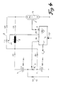
- FIGS. 1-3 shows a basic circuit diagram of how the three burn-off curves can be set according to FIGS. 1-3.
- 1 and 2 denote two partial capacitances C 1 and C 2, which can be connected to one another in series via a first electronic switching element 3, namely a tyristor T 1, when the tyristor is switched through.
- the two partial capacitances lie in a discharge circuit with a discharge tube 4, which has an ignition electrode 5, which is connected to an output 6 of a control unit 7 to be explained in more detail.
- An inductance 8 is also provided in the discharge circuit and can be bridged with a second electronic switching element 10 via a parallel branch 9.
- the second electronic switching element 10 is a second tyristor T 2.
- a parallel branch which contains a diode 11, is guided in parallel across the first partial capacitance C 1.
- the anodes of the two capacitors are connected to further diodes 12 and 13.
- Diodes 14 and 15 are also arranged in the circuit and in parallel branch 9.
- the tyristors that form the two electronic switching elements 3 and 10 are ignited by outputs 16 and 17 in the controller 7.
- the entire flash process can be initiated via an input 18 on the controller 7 that can be connected to a camera.
- a normal discharge, a blue-shifted discharge, a red-shifted discharge or a mixture thereof takes place in the discharge circuit. If output 6 is triggered, for example, but outputs 16 and 17 are not, however, a discharge process according to FIG. 3 will result. If output 6 is triggered, then output 16 is ignited a little later within the discharge time, but output 17 is not ignited, then the discharge according to FIG. 3 will take place first and then after triggering output 16, a discharge peak will be superimposed, which is similar to FIG. 2.
- the relative ignition times of the outputs 16 and 17 in relation to that of the output 6 should be able to be entered by means of a control button 20, by means of which a continuous shift of the color temperature values is possible.
- the controller 7 also has another charging output 25 for the capacitors 1 and 2.
- the partial capacitances 1 and 2 according to FIG. 4 are now formed by sub-capacitances 101 and 102, each partial capacitance 101 and 102 being able to be charged separately via charging pyristors 130 and 132.
- the output of the flash unit can thus also be regulated by varying the capacity to be discharged while maintaining the variation option for the color temperature control.
Landscapes
- Physics & Mathematics (AREA)
- General Physics & Mathematics (AREA)
- Stroboscope Apparatuses (AREA)
- Discharge-Lamp Control Circuits And Pulse- Feed Circuits (AREA)
- Physical Or Chemical Processes And Apparatus (AREA)
Applications Claiming Priority (2)
| Application Number | Priority Date | Filing Date | Title |
|---|---|---|---|
| DE4125322 | 1991-07-31 | ||
| DE4125322A DE4125322C2 (de) | 1991-07-31 | 1991-07-31 | Verfahren zur Steuerung eines Blitzgerätes sowie Blitzgerät, insbesondere Studioblitzanlage |
Publications (2)
| Publication Number | Publication Date |
|---|---|
| EP0525340A1 true EP0525340A1 (fr) | 1993-02-03 |
| EP0525340B1 EP0525340B1 (fr) | 1996-08-28 |
Family
ID=6437385
Family Applications (1)
| Application Number | Title | Priority Date | Filing Date |
|---|---|---|---|
| EP92109747A Expired - Lifetime EP0525340B1 (fr) | 1991-07-31 | 1992-06-10 | Procédé de contrÔle d'un flash, et dispositif à flash, notamment une disposition d'un flash de studio |
Country Status (4)
| Country | Link |
|---|---|
| EP (1) | EP0525340B1 (fr) |
| JP (1) | JPH076891A (fr) |
| AT (1) | ATE142029T1 (fr) |
| DE (2) | DE4125322C2 (fr) |
Cited By (1)
| Publication number | Priority date | Publication date | Assignee | Title |
|---|---|---|---|---|
| US5932282A (en) * | 1996-08-31 | 1999-08-03 | Herberts Gesellschaft Mit Beschrankter Haftung | Process for producing a repair coating |
Families Citing this family (2)
| Publication number | Priority date | Publication date | Assignee | Title |
|---|---|---|---|---|
| DE102007043093A1 (de) | 2007-09-10 | 2009-03-12 | Bron Elektronik Ag | Farbtemperatursteuerung von Blitzgeräten |
| JP5533452B2 (ja) * | 2010-08-31 | 2014-06-25 | 株式会社リコー | ビデオカメラ装置 |
Citations (2)
| Publication number | Priority date | Publication date | Assignee | Title |
|---|---|---|---|---|
| EP0240789A1 (fr) * | 1986-04-11 | 1987-10-14 | Urs Zeltner | Dispositif d'éclairage et de flash |
| FR2652478A1 (fr) * | 1989-09-27 | 1991-03-29 | Bron Elektronik Ag | Appareil d'eclairage et/ou a lumiere eclair. |
Family Cites Families (5)
| Publication number | Priority date | Publication date | Assignee | Title |
|---|---|---|---|---|
| DE969604C (de) * | 1955-01-16 | 1958-06-26 | Elektronik Ges Mit Beschraenkt | Elektrische Blitzlichteinrichtung mit veraenderbarer Entladungsdauer |
| FR1592537A (fr) * | 1968-06-07 | 1970-05-19 | ||
| JPS528188B2 (fr) * | 1973-06-15 | 1977-03-07 | ||
| US4467248A (en) * | 1980-04-09 | 1984-08-21 | Konishiroku Photo Industry Co., Ltd. | Variable electronic flash light equipment |
| DE3931407A1 (de) * | 1989-09-20 | 1991-03-28 | Heimann Gmbh | Zuendschaltung fuer eine blitzlampe |
-
1991
- 1991-07-31 DE DE4125322A patent/DE4125322C2/de not_active Expired - Fee Related
-
1992
- 1992-06-10 AT AT92109747T patent/ATE142029T1/de not_active IP Right Cessation
- 1992-06-10 EP EP92109747A patent/EP0525340B1/fr not_active Expired - Lifetime
- 1992-06-10 DE DE59206986T patent/DE59206986D1/de not_active Expired - Fee Related
- 1992-07-28 JP JP4201376A patent/JPH076891A/ja active Pending
Patent Citations (2)
| Publication number | Priority date | Publication date | Assignee | Title |
|---|---|---|---|---|
| EP0240789A1 (fr) * | 1986-04-11 | 1987-10-14 | Urs Zeltner | Dispositif d'éclairage et de flash |
| FR2652478A1 (fr) * | 1989-09-27 | 1991-03-29 | Bron Elektronik Ag | Appareil d'eclairage et/ou a lumiere eclair. |
Non-Patent Citations (1)
| Title |
|---|
| PATENT ABSTRACTS OF JAPAN vol. 7, no. 154 (E-185)6. Juli 1983 & JP-A-58 061 690 ( TOKYO SHIBAURA DENKI ) * |
Cited By (1)
| Publication number | Priority date | Publication date | Assignee | Title |
|---|---|---|---|---|
| US5932282A (en) * | 1996-08-31 | 1999-08-03 | Herberts Gesellschaft Mit Beschrankter Haftung | Process for producing a repair coating |
Also Published As
| Publication number | Publication date |
|---|---|
| ATE142029T1 (de) | 1996-09-15 |
| EP0525340B1 (fr) | 1996-08-28 |
| JPH076891A (ja) | 1995-01-10 |
| DE4125322C2 (de) | 1994-01-20 |
| DE4125322A1 (de) | 1993-02-04 |
| DE59206986D1 (de) | 1996-10-02 |
Similar Documents
| Publication | Publication Date | Title |
|---|---|---|
| DE3407067C2 (de) | Steuerschaltung für Gasentladungslampen | |
| DE10026070B4 (de) | Vorschaltgerät für eine Entladungslampe | |
| EP0240789B1 (fr) | Dispositif d'éclairage et de flash | |
| DE3152974C2 (de) | Objektiv-Scharfeinstellvorrichtung für Filmkameras o. dgl. | |
| DE2936063A1 (de) | Dimmerschaltkreis | |
| EP2189046B1 (fr) | Commande de la température de couleur des flasheuses | |
| DE3300396C2 (de) | Blitzlichtfotografievorrichtung | |
| DE10051139A1 (de) | Elektronisches Vorschaltgerät mit Vollbrückenschaltung | |
| EP0525340B1 (fr) | Procédé de contrÔle d'un flash, et dispositif à flash, notamment une disposition d'un flash de studio | |
| DE3103605C2 (de) | Klopfdetektor zur Verwendung bei einer Zündzeitpunkteinstelleinrichtung für eine Brennkraftmaschine mit Funkenzündung | |
| DE102006005128A1 (de) | Verfahren und Vorrichtung zur Lastanpassung | |
| DE2446827A1 (de) | Steuerschaltung fuer ein blitzlicht | |
| DE3046099C2 (de) | Steuerschaltung für eine elektronische Blitzlichtanordnung | |
| DE2427254A1 (de) | Studiolichtanlage | |
| DE2165602C2 (de) | Anordnung zur Erzeugung einer sich mit hoher Frequenz zyklisch stufenweise ändernden hohen Ausgangsgleichspannung | |
| DE2160720C3 (de) | Kamera mit einer BelichtungsmeBschaltung und einem Elektronenblitzgerät | |
| DE2719373A1 (de) | Schaltungsanordnung fuer einen roentgengenerator | |
| DE3033536C2 (fr) | ||
| DE69315640T2 (de) | Verzögerungsmittel in einer Anlaufschaltung eines Vorschaltgerätes | |
| DE2624866B2 (de) | Vorrichtung zur Steuerung der von einer Lichtquelle auf ein zu belichtendes Material abgegebenen Lichtmenge | |
| DE3242031C2 (fr) | ||
| DE3637645C2 (fr) | ||
| DE3709004C2 (fr) | ||
| DE102004031913A1 (de) | Ladungspumpe einer Phasenregelschleife mit umschaltbarer Systembandbreite und Verfahren zur Steuerung einer solchen Ladungspumpe | |
| DE2846933A1 (de) | Schaltungsanordnung zum wahlweisen zufuehren von energie zu einer elektronenblitzroehre |
Legal Events
| Date | Code | Title | Description |
|---|---|---|---|
| PUAI | Public reference made under article 153(3) epc to a published international application that has entered the european phase |
Free format text: ORIGINAL CODE: 0009012 |
|
| AK | Designated contracting states |
Kind code of ref document: A1 Designated state(s): AT BE CH DE DK ES FR GB GR IT LI LU MC NL PT SE |
|
| 17P | Request for examination filed |
Effective date: 19930120 |
|
| 17Q | First examination report despatched |
Effective date: 19950109 |
|
| GRAH | Despatch of communication of intention to grant a patent |
Free format text: ORIGINAL CODE: EPIDOS IGRA |
|
| GRAH | Despatch of communication of intention to grant a patent |
Free format text: ORIGINAL CODE: EPIDOS IGRA |
|
| GRAA | (expected) grant |
Free format text: ORIGINAL CODE: 0009210 |
|
| AK | Designated contracting states |
Kind code of ref document: B1 Designated state(s): AT BE CH DE DK ES FR GB GR IT LI LU MC NL PT SE |
|
| PG25 | Lapsed in a contracting state [announced via postgrant information from national office to epo] |
Ref country code: ES Free format text: THE PATENT HAS BEEN ANNULLED BY A DECISION OF A NATIONAL AUTHORITY Effective date: 19960828 Ref country code: IT Free format text: LAPSE BECAUSE OF FAILURE TO SUBMIT A TRANSLATION OF THE DESCRIPTION OR TO PAY THE FEE WITHIN THE PRE;WARNING: LAPSES OF ITALIAN PATENTS WITH EFFECTIVE DATE BEFORE 2007 MAY HAVE OCCURRED AT ANY TIME BEFORE 2007. THE CORRECT EFFECTIVE DATE MAY BE DIFFERENT FROM THE ONE RECORDED.SCRIBED TIME-LIMIT Effective date: 19960828 Ref country code: NL Free format text: LAPSE BECAUSE OF FAILURE TO SUBMIT A TRANSLATION OF THE DESCRIPTION OR TO PAY THE FEE WITHIN THE PRESCRIBED TIME-LIMIT Effective date: 19960828 Ref country code: GR Free format text: LAPSE BECAUSE OF FAILURE TO SUBMIT A TRANSLATION OF THE DESCRIPTION OR TO PAY THE FEE WITHIN THE PRESCRIBED TIME-LIMIT Effective date: 19960828 Ref country code: DK Effective date: 19960828 |
|
| REF | Corresponds to: |
Ref document number: 142029 Country of ref document: AT Date of ref document: 19960915 Kind code of ref document: T |
|
| ET | Fr: translation filed | ||
| REF | Corresponds to: |
Ref document number: 59206986 Country of ref document: DE Date of ref document: 19961002 |
|
| PG25 | Lapsed in a contracting state [announced via postgrant information from national office to epo] |
Ref country code: SE Effective date: 19961128 Ref country code: PT Effective date: 19961128 |
|
| GBT | Gb: translation of ep patent filed (gb section 77(6)(a)/1977) |
Effective date: 19961129 |
|
| NLV1 | Nl: lapsed or annulled due to failure to fulfill the requirements of art. 29p and 29m of the patents act | ||
| PG25 | Lapsed in a contracting state [announced via postgrant information from national office to epo] |
Ref country code: AT Free format text: LAPSE BECAUSE OF NON-PAYMENT OF DUE FEES Effective date: 19970610 |
|
| PG25 | Lapsed in a contracting state [announced via postgrant information from national office to epo] |
Ref country code: LU Free format text: LAPSE BECAUSE OF NON-PAYMENT OF DUE FEES Effective date: 19970630 Ref country code: BE Effective date: 19970630 |
|
| PLBE | No opposition filed within time limit |
Free format text: ORIGINAL CODE: 0009261 |
|
| STAA | Information on the status of an ep patent application or granted ep patent |
Free format text: STATUS: NO OPPOSITION FILED WITHIN TIME LIMIT |
|
| 26N | No opposition filed | ||
| BERE | Be: lapsed |
Owner name: STUDIOTECHNIK HENSEL VERTRIEBS G.M.B.H. Effective date: 19970630 |
|
| PG25 | Lapsed in a contracting state [announced via postgrant information from national office to epo] |
Ref country code: MC Effective date: 19971231 |
|
| REG | Reference to a national code |
Ref country code: CH Ref legal event code: PL |
|
| REG | Reference to a national code |
Ref country code: CH Ref legal event code: AEN Free format text: DAS PATENT IST AUFGRUND DES WEITERBEHANDLUNGSANTRAG VOM 13.02.1998 REAKTIVIERT WORDEN. |
|
| REG | Reference to a national code |
Ref country code: CH Ref legal event code: NV Representative=s name: PATENTANWALTSBUERO EDER AG |
|
| REG | Reference to a national code |
Ref country code: GB Ref legal event code: IF02 |
|
| PGFP | Annual fee paid to national office [announced via postgrant information from national office to epo] |
Ref country code: GB Payment date: 20030521 Year of fee payment: 12 |
|
| PGFP | Annual fee paid to national office [announced via postgrant information from national office to epo] |
Ref country code: FR Payment date: 20030618 Year of fee payment: 12 |
|
| PGFP | Annual fee paid to national office [announced via postgrant information from national office to epo] |
Ref country code: CH Payment date: 20030625 Year of fee payment: 12 |
|
| PGFP | Annual fee paid to national office [announced via postgrant information from national office to epo] |
Ref country code: DE Payment date: 20031121 Year of fee payment: 12 |
|
| PG25 | Lapsed in a contracting state [announced via postgrant information from national office to epo] |
Ref country code: GB Free format text: LAPSE BECAUSE OF NON-PAYMENT OF DUE FEES Effective date: 20040610 |
|
| PG25 | Lapsed in a contracting state [announced via postgrant information from national office to epo] |
Ref country code: CH Free format text: LAPSE BECAUSE OF NON-PAYMENT OF DUE FEES Effective date: 20040630 Ref country code: LI Free format text: LAPSE BECAUSE OF NON-PAYMENT OF DUE FEES Effective date: 20040630 |
|
| PG25 | Lapsed in a contracting state [announced via postgrant information from national office to epo] |
Ref country code: DE Free format text: LAPSE BECAUSE OF NON-PAYMENT OF DUE FEES Effective date: 20050101 |
|
| GBPC | Gb: european patent ceased through non-payment of renewal fee |
Effective date: 20040610 |
|
| REG | Reference to a national code |
Ref country code: CH Ref legal event code: PL |
|
| PG25 | Lapsed in a contracting state [announced via postgrant information from national office to epo] |
Ref country code: FR Free format text: LAPSE BECAUSE OF NON-PAYMENT OF DUE FEES Effective date: 20050228 |
|
| REG | Reference to a national code |
Ref country code: FR Ref legal event code: ST |